
Abstract
Nine kinds of carbide nose radius worn tools were used in turning of high-strength carbon-fiber-reinforced-plastics (CFRP) materials to study the cutting temperature of tip's surface. A new cutting temperature model using the variations of shear and friction plane areas occurring in tool nose wear situations are presented in this paper. The frictional forces and heat generated in the cutting process are calculated by using the measured cutting forces and the theoretical cutting analysis. The heat partition factor between the tip and chip is solved by using the inverse heat transfer analysis, which utilizes temperature on the K type carbide tip's surface measured by infrared as the input. The tip's surface temperature is determined by finite element analysis (FEA) and compared with temperatures obtained from experimental measurements. Good agreement demonstrates the proposed model.
Introduction
Carbon-fiber-reinforced plastics (CFRP) are also widely used in the structures of aircraft, robots and other machines because of their high strength to weight ratio, and high clamping capacity. Konig et al. 1 presented in spite of the near net shape production technology available for the processing, molding and curing of fiber reinforced plastics (FRP); these materials have to be machined. Machining characteristics of composites vary from metals due to the following reasons: (1) FRP is machinable in a limited range of temperature; (2) the low thermal conductivity causes heat build up in the cutting zone during machining operation, since there is only little dissipation by the materials 2 . Singamneni 3 demonstrated the mixed finite and boundary element method (FEM) finally enables the estimation of the cutting temperatures which is a simple, efficient method, and at the same time it is quite easy to be implemented. The objective of this paper is to set up an oblique cutting CFRP model to study the cutting temperature for a nose radius worn tool with a chamfered main cutting edge.
Theoretical Analyses
Wang et al.
4
illustrated that chip formation, cutting forces, and the surface morphology in edge trimming of unidirectional graphite/epoxy was highly dependent on fiber orientation. Bhatnagar et al.
5
showed that in machining of fiber reinforced plastic (FRP) composite laminates; it can be assumed that the shear plane in the matrix depends only on the fiber orientation and not on the tool geometry. Nakayama et al.
6
and Chang
7
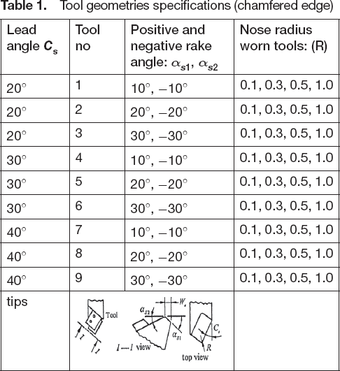
investigated the relationship between the cutting forces, temperatures, surface roughness and BUE; the results indicated that the cutting forces were low when BUE was present. For the case of chamfered main cutting edge, must have not only nose radius R, worn depths d
B
, cutting depth d, feed rate f, cutting speed V, back rake angle α
b
, side cutting edge angle C
s
, end side cutting edge angle C
e
, negative side rake angle, αs1 and positive rake angle α
s2
are used as shown in


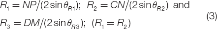


Model of the chamfered main cutting edge nose radius tool with wear f > R, (R ≠ 0)

Specifications of nose radius with wear
Tool geometries specifications (chamfered edge)
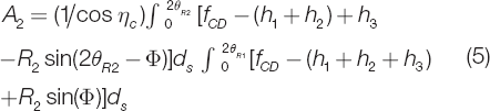
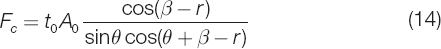
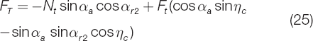
Cutting Forces Calculation
Transformation equations used to obtain the normal (N
s
) and shear forces (F
s
) along the fiber direction in terms of the principal (F
c
) and thrust components (F
t
) are shown in Eqs. (14) and (15)


Solid Modeling of Carbide Tip
To develop a 3D FEM model for thermal analysis, the tip cross-section profile perpendicular to the cutting edge was measured using a microscope, Solid Works™, was used to generate the tip body by sweeping the PCMD along the main cutting edge, as shown in
Finite Element Model
The Abaqus™ is used in this study. The finite element mesh of the carbide tip is shown in

Flow chart of heat calculate

Solid model of cutting tool
Modified Carbide Tip Temperature Model
Magnitude of the tip's load is shown in the following Eqs. (33) and (34)


Calculation of the contact length (a) L f and (b) L p
Inverse Heat Transfer Solution and Validation
The flowchart for inverse heat transfer solution of K was obtained by the Abaqus™ software and is summarized in

Experimental set up is shown in

Experimental set-up
Properties of the work materials (roving continuous strand, hardness, HS: 55–60) 11

The Cutting Forces
Chang demonstrated in turning of CFRP with chamfered main cutting edge nose radius tools, the resultant cutting force, Fr, is about 15% less than that for unchamfered main cutting edge nose radius tools13–15. As well as in the case of turning CFRP with chamfered main cutting nose radius worn tools, it shows the theoretical cutting forces are good agreement with the experimental values,

The theoretical resultant cutting force, Fr (N) with K type chamfered nose radius worn tools vs. C S (°) for different values of αs1 and αs2 (°) at d = 3 mm, f = .457 mm/rev and V = 252 m/min (CFRP)
Temperature of Surface of Tip
Inverse heat transfer utilizes the temperature measured by infrared on the surface of tip as the input to predict the heat flux on the chamfered main cutting edge tools. An infrared (IR) pyrometer system with an optical fiber was developed for measuring the temperature of a chamfered main cutting edge tool during turning. Based on Li and Albert
11
, according to Eqs. (38) to (39), the flowchart for inverse heat transfer solution of K is described in

Cutting temperatures versus cutting time for different values αs1 and αs2 with unchamfered and chamfered nose radius worn tools at d = 3.0 mm, f = 0.33 mm/rev, V = 252 m/min and C s = 30° (CFRP)

Temperature distribution with chamfered cutting edge inserts (a) heat flux (b) near the tool nose at C s = 30°, αs1 (αs2) = −10°(10°), d = 3.0 mm, f = 0.33 mm/rev, and V = 252 m/min (CFRP)
From
According to
From
From
The test investigated the cutting forces and cutting temperature during the turning of CFRP. Chamfered main cutting edge nose radius worn tools with C S equals to 20°, αs1 (αs2) = −10°(10°) and nose radius R = 0.3 mm, produce the lower cutting forces and lower cutting temperature. Good correlations between predicted values and experimental results of forces and temperatures during machining with nose radius worn tools in cutting CFRP. The FEM and Inverse heat transfer solution in tool temperature in CFRP turning is obtained and compared with experimental measurements. The good agreement demonstrates the accuracy of proposed model.