
Abstract
Considering the fact that the foundation data for a new X850 ± IM190 carbon/epoxy material system adopted in commercial aircraft industry are extremely scarce in the literature, an in-plane, static tensile experiment was carried out to investigate the bearing performance of double-lap, single-bolt joints in X850 ± IM190 carbon fiber-reinforced polymer (CFRP) composites. The effects of ply ratio, 0° layers’ combination percentage, bolt diameter, and curing method were considered. Then, special attention was paid to determine the design parameters of X850 ± IM190 CFRP bolted joints, such as tensile strength of un-notched laminate and stress concentration relief factor. Based on these design parameters, an efficient semianalytical approach was established to obtain the ultimate bearing strength of the joints. The failure prediction exhibited excellent agreement with the experimental data. These results will play an important role in design and strength evaluation of X850 ± IM190 CFRP bolted joints.
Keywords
Nomenclature
W, D, e: width, bolt diameter, edge distance of the joint configuration
L: length of the composite laminate and titanium plate
g: length of the gripping section
t
T: thickness of the titanium plate
t
C: laminate thickness
E
1, E
2, G
12: longitudinal, transverse, in-plane shear Young’s modulus
v
12: in-plane Poison’s ratio
X
T, X
C: longitudinal tensile and compressive strength
Y
T, Y
C: transverse tensile and compressive strength
S
12: in-plane shear strength
E
T, E
bolt: Young’s modulus of the titanium plate and fastener
τ
s, τ: shear strength of the fastener and bolted joints
K: joint stiffness
E
xx: equivalent Young’s modulus of orthotropic laminates
P
ult: ultimate failure load of the mechanically fastened composite joints
σ
bru: ultimate bearing strength of the mechanically fastened composite joints
C: stress concentration relief factor
σ
t: tensile strength of un-notched laminates
K
bc: stress concentration factor corresponding to bearing stress of double-lap, single-bolt, composite joints
x: variation of 0° ply ratio
Introduction
Composite materials are extensively used in modern aircraft structures due to their favorable lightweight material properties. 1 –4 In manufacturing process, it is virtually impossible to make a whole composite structure as a single body. When composite components are fastened to other structural members, bolted joints are the primary choices due to their facility to assemble, dissemble, and repair. 5 Since composite bolted joints need to be drilled in laminates, the stress concentration around the fastener holes decreases the load carrying capacity of the composite structures. Bolted joints become a critical part of the structures. Therefore, it is necessary to investigate techniques to improve the structural efficiencies of bolted joints.
State-of-the-art
Depending on the geometric features, the properties of the composite material, and the assembly factors (preload and clearance), different failure modes can occur for composite bolted joints. 6,7 These common failure modes are bearing, net-tension, and shear-out (Figure 1). The geometric factors that most affect failure modes are the width of specimen W, the edge distance e, the bolt diameter D, and the layup pattern of composite laminate.

Common failure modes in composite bolted joint.
Extensive methodologies have been conducted to exploit the failure mechanism of the composite bolted joints by means of experimental and numerical methods. The influence of several design variables is considered, including the width, bolt diameter, edge distance, and fiber orientation. A large number of papers performed in the past have established specified minimum joint configuration details, such as the geometric ratios of width and bolt diameter (W/D ratio) and edge distance and bolt diameter (e/D ratio).
For single-bolt joints, Zhou et al. 8 proposed minimum geometric ratios on the basis of composite bolted joints made by vacuum-assisted resin injection, with a plain shank steel bolt of 8 mm and a constant torque equal to 6 Nm. On the contrary, Cooper and Turvey 9 used single-bolt tension joints in pultruded fiber-reinforced polymer material with three different torque levels to 30 Nm, obtaining ultimate failure load larger than 50%. Moreover, Tang et al. 10 changed the W/D and e/D ratios by considering the effect of friction. Khashaba et al. 11 showed that for material orientations of 15° and 30°, the cracks propagated along the reinforcement angle. Finally, Pakdil et al. 12 investigated the effect of changing laminate layup and bolt torque on single-bolt joints, showing that increasing preload is seen to be suitable for a safe bolted joint structure due to the providing bearing failure mode. Meanwhile, the orientation (0°/0°/90°/90°)s exhibits stronger bearing strength than the orientation (60°/60°/−60°/−60°)s.
When the failed laminate causes joint failure, the experimental and numerical results show that the failure modes including bearing, shear-out, and net-tension can occur by changing W/D and e/D ratios. 13 –16 In summary, when the geometric ratios e/D and W/D are less than 2 and 4, respectively, or when certain amounts of 45° plies do not exist, the failure mode of single-bolt joints is not bearing and there is no joint ductility. Moreover, when the load is perpendicular to the reinforced angle, the net-tension brittle failure mode may occur, and the ultimate failure load is 30% smaller than that of the 0° joint. 17 Finally, it is demonstrated that the failure mode does not change with increasing bolt torque, if the e/D ratio is greater than 4. 18
For multibolt joints, Zhang et al. 19 –21 proposed a numerical progressive damage method to trace the damage process from the onset and propagation up to ultimate failure of the joints. They found that net-tension failure occurred at the first bolt from the free edges when there was a single row of bolts and e/D = 2. In a multirow joint, the first bolt row experienced the most serious stress concentration because of the highest resultant bolt-load (because of bearing); the joints exhibited net-tension failure mode (e/D > 2). Because all hi-shear bolts were preloaded, joints showed bearing deformations after failure. A series of experimental studies by Yun et al. 22 on specimens characterized by a single vertical plate of five bolts, geometric e/D ratios, and pitch distance and bolt diameter greater than 7 mm showed that positive clearance could alleviate the stress concentration around the bolt-hole and lead to a more uniform load distribution. The state-of-the-art studies on multibolt joints show that failure is at the first row and their typical failure modes are net-tension. 23 Thus, the multibolt joints exhibit less damage tolerance than joints with a single bolt.
In recent years, the high-strength X850 ± IM190 carbon/epoxy laminate is being adopted as a new composite material in commercial aircraft industry. However, few data in the literature are available on bearing characteristics of X850 ± IM190 carbon fiber-reinforced polymer (CFRP) bolted joints and even less for design parameters associated with this kind of composite material, such as tensile strength of un-notched laminate and stress concentration relief factor (SCRF). The main objective of this article is to carry out a systematic study to analyze the bearing performance of double-lap, single-bolt joints in X850 ± IM190 CFRP composites. The effects of ply ratio, 0° layers’ combination percentage, bolt diameter, and curing method are considered. Design parameters are another major concern of this article as these are significantly important in strength prediction of composite bolted joints.
Experiment
Specimen preparation
Based on the ASTM D5961, 24 the configuration of a double-lap, single-bolt joints in X850 ± IM190 CFRP composites is shown in Figure 2. Hi-shear protruding head fastener is used to join the composite laminate and titanium plates. Joint configuration with edge distance e = 40 mm, width W = 70 mm, and a hole of bolt diameter D is considered. Here, L = 290 mm is the length of the composite laminate and titanium plate, g = 156 mm is the length of the gripping section, and t T = 5.7 mm is the thickness of the titanium plate. The laminate is manufactured using unidirectional prepreg X850 ± IM190. Ply thickness of the prepreg after curing is 0.188 mm. Ply ratios and stacking sequences investigated are given in Table 1. B1-D1 and B2-B3 represent 60-ply laminate with laminate thickness t C = 11.28 mm. A1 stands for 64-ply laminate with laminate thickness t C = 12.08 mm, equally regarded as 60-ply laminate. As shown in Figure 2, X -axis is the direction of 0° ply and Y-axis is the direction of 90° ply.

Geometry of double-lap, single-bolt joints in X850 ± IM190 CFRP composites. CFRP: carbon fiber-reinforced polymer.
Ply ratios and stacking sequences investigated.

Material property
The mechanical property of X850 ± IM190 carbon/epoxy laminate is given in Table 2, in which the parameters are provided by the manufacturers. The titanium plate and hi-shear protruded head fastener are made of Ti-6Al-4 V titanium alloy, of which Young’s modulus are E T = 110 GPa and E bolt = 110 GPa, respectively. For the hi-shear protruded head fastener, the shear strength is τ s = 654 MPa. 25
Mechanical property of X850 ± IM190 carbon/epoxy laminate.

Test matrix
Detailed information about the joint configurations is outlined in Table 3. Each joint configuration is marked with a label. Take A1-12.8-C as an example. In label A1-12.8-C, A1 stands for ply code, 12.8 for bolt diameter, and C for co-cured method. Additionally, S stands for secondary bonding method.
Test matrix.

The first objective of the test is to investigate the effect of ply ratio on joint stiffness and bearing strength of the X850 ± IM190 CFRP bolted joints. A1-12.8-C, B1-12.8-C, C1-12.8-C, and D1-12.8-C with different ply ratios—((0°)25%/(±45°)50%/(90°)25%), ((0°)30%/(±45°)60%/(90°)10%), ((0°)50%/(±45°)40%/(90°)10%), and ((0°)70%/(±45°)20%/(90°)10%)—are chosen. Then, B1-12.8-C, B2-12.8-C, and B3-12.8-C with different 0° layers’ combination percentages—33%, 66%, and 100%—are selected to investigate the effect of 0° layers’ combination percentages. Next, to study the effect of bolt diameter, B1-9.53-C, B1-12.8-C, and B1-14.3-C with different bolt diameters—9.53, 12.8, and 14.3 mm—are considered. Finally, to evaluate the effect of curing method, B1-12.8-C and B1-12.8-S are chosen. Laminate in B1-12.8-S is manufactured using secondary bonding method, while laminates in other joint configurations are manufactured using co-cured technology in a hot press.
Test procedure
Figure 3 shows the test-up for X850 ± IM190 CFRP bolted joint. In Figure 3(a), the free end of the titanium plates is fixed. The tensile load is along the X-axis, which is the direction of 0° ply. Displacement gauges are placed at two points A and B on the joint to measure the relative displacement between one of the titanium plates and the central laminate. In Figure 3(b), a LYG40 T testing machine is used and the loading speed is 1.5 mm/min.
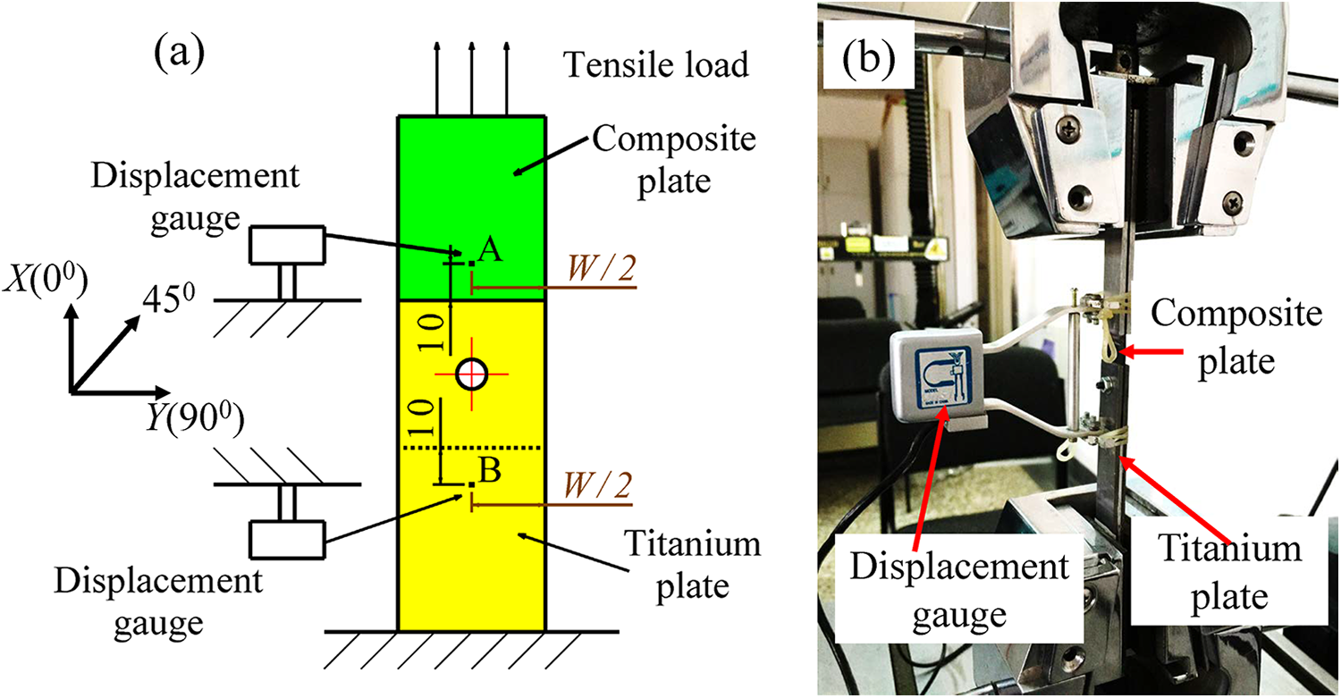
(a) Detail and (b) image of test set-up for X850 ± IM190 CFRP bolted joint (unit: mm). CFRP: carbon fiber-reinforced polymer.
Each test configuration is repeated with five specimens. Bearing stress/bearing strain curve is acquired in accordance with ASTM D5961 standard and shown for one specimen of each configuration as representative. The average in terms of joint stiffness and bearing strength of five specimens is taken as the results of each test configuration. The resulting bearing stress–strain curve of D1-12.8-C is shown in Figure 4. From this curve, joint stiffness, 2% offset bearing strength, and ultimate bearing strength are deduced. Based on the ASTM5961 standard, there is no internal connection between ultimate bearing capacity and 2% offset bearing strength.

Representative bearing stress–strain curve showing the calculation of joint stiffness and bearing strength.
Experimental results and discussions
Failure mode
In the experiment, bearing failure mode and shear-out failure mode are observed. It can be inferred that the failure mode is directly related to the ±45° ply ratio. D1-12.8-C experiences shear-out failure mode while the other joint configurations exhibit bearing failure mode. The ±45° ply ratio in D1-12.8-C is 20%, but ±45° ply ratios in other joint configurations are up to 40%, 50%, and 60%, respectively. The ±45° layers play an important role in resisting the in-plane shear stress and maximizing the bearing strength. The 0° layers’ combination percentage, bolt diameter, and curing method do not affect the failure mode just as they do affect the joint stiffness and bearing strength.
To observe the internal damage in detail, fracture surfaces of joint configurations damaged in bearing and shear-out failure modes are examined by scanning electron microscope (SEM), respectively. Figure 5(a) shows a graphic representation of bearing failure hole after test: the fibers and matrix chipping out and rushing on the edge of the holes are too severe. Figure 5(b) shows the SEM examination of the fractured surface in bearing specimens. It is observed that local fiber kinking at the compression side of the hole is the main damage mechanism in the bearing process and determines the bearing capacity

Bearing failure mechanism in C1-14.3-C: (a) optical and (b) SEM photographs. SEM: scanning electron microscope.
Figure 6(a) shows that failure in shear-out samples has appeared as cracks in the application of tensile load. Figure 6(b) exhibits the catastrophic nature of the shear-out failure mode. It can be inferred that the crack initially develops in the matrix. With the load increasing and overcoming adhesion strength on matrix–fiber interfaces, tension breaking of fiber is evident. Then, it is the matrix carrying the tensile load. Since the matrix lacks enough material strength, shear-out failure mode is accepted when the crack propagates along the shear-out plane to the edge of the laminate.
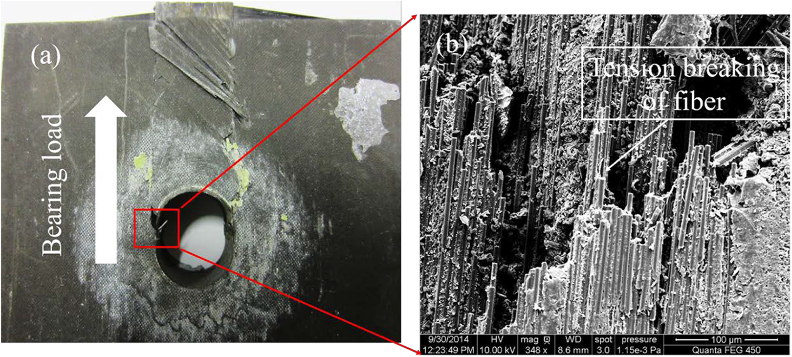
Shear-out failure mechanism in D1-14.3-C: (a) optical and (b) SEM photographs. SEM: scanning electron microscope.
Effect of ply ratio
Figure 7 shows the bearing stress–strain curves of X850 ± IM190 CFRP bolted joints with different ply ratios. Joint configurations A1-12.8-C, B1-12.8-C, C1-12.8-C, and D1-12.8-C with various ply ratios—((0°)25%/(±45°)50%/(90°)25%), ((0°)30%/(±45°)60%/(90°)10%), ((0°)50%/(±45°)40%/(90°)10%), and ((0°)70%/(±45°)20%/(90°)10%)—are chosen. It is clear that the joint stiffness increases as the 0° ply ratio increases. Two typical kinds of bearing stress–strain curves are observed in Figure 5. All curves include four stages except for D1-12.8-C, which includes three stages. The first three stages in both kinds of bearing strain curves are the same. The curves in Figure 5 will be explained briefly.

Bearing stress–strain curves of X850 ± IM190 CFRP bolted joints with different ply ratios. CFRP: carbon fiber-reinforced polymer.
For the first two stages, linear behavior is observed with the increment of tensile load. Since no bearing deformation appears and tensile load is transferred by the friction load between titanium plates and laminate, the first stage exhibits the highest slope in the curves. Then, the slope of the curves has a little decrease, as friction does not increase anymore in this stage and significant load is transmitted through the bolt.
During the third stage, the slope of the curves exhibits a gradual decrease, which indicates that the bearing damage occurs in central laminate and keeps on growing as the tensile load applied. At the end of this stage, D1-12.8-C tears suddenly and loses its load carrying capability due to disastrous shear-out damage. In the final stage, the curves in other three joint configurations show another almost linear stage, meaning the fastener is into plastic yield state. In the end, fastener is sheared off with obvious bearing damage found around the hole of the laminate. These three joint configurations almost fail at the same load and lose their bearing load capability completely.
Figure 8 shows that the values of the joint stiffness increase in a nonlinear form with the increase of 0° ply ratio. This nonlinear increase behavior qualitatively agrees with the predicted values of equivalent Young’s modulus E xx of orthotropic laminates with different ply ratios using classical laminate theory, which can be explained by equation (1). Here, the joint stiffness K 13 can be determined as follows:


Joint stiffness of X850 ± IM190 CFRP bolted joints with different 0° ply ratios. CFRP: carbon fiber-reinforced polymer.
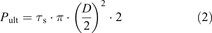
Figure 9 shows that ±45° layer is important to maximize the 2% offset bearing strength. A1-12.8-C with ±45° ply ratio equal to 50% has the highest 2% offset bearing strength compared to other joint configurations. This is due to the presence of ±45° layer resisting the in-plane shear stress and delaying the initial bearing damage of the composite laminate. 11 However, when ±45° ply ratio increases to 60%, the nonlinearity of the laminate enhances. Instead, this enhanced nonlinearity lowers the 2% offset bearing strength of joint configuration B1-12.8-C. Contrary to other joint configurations, D1-12.8-C with the fewest ±45° ply ratio has the lowest 2% offset bearing strength and ultimate bearing strength. This is because D1-12.8-C has the minimum in-plane shear strength. For bearing joint configurations with fastener fracture, the ultimate bearing strength is almost the same and closely related to the shear strength of fastener τ s and the bolt diameter/laminate thickness ratio (D/t C). Under such circumstances, the ultimate failure load P ult and ultimate bearing strength σ bru of the mechanically fastened composite joints can be calculated as follows:

Bearing strength of X850 ± IM190 CFRP bolted joints with different ±45° ply ratios. CFRP: carbon fiber-reinforced polymer.
Effect of 0° layers’ combination percentage
Figure 10 shows the bearing stress–strain curves of X850 ± IM190 CFRP bolted joints with different 0° layers’ combination percentages. Joint configurations B1-12.8-C, B2-12.8-C, and B3-12.8-C with various 0° layers’ combination percentages—33%, 66%, and 100%—are selected. All these joint configurations are damaged in bearing failure mode accompanying with fastener fracture. These bearing stress–strain curves can be divided into the aforementioned four typical stages. For joint configurations with different 0° layers’ combination percentages, coincidence is detected in the first two linear stages. Then, divergence appears in the third stage. Joint configuration with lower 0° layers’ combination percentage exhibits higher bearing strength in this stage. Finally, joint configurations with fastener fracture completely lose their load carrying capability under the same tensile load.

Bearing stress–strain curves of X850 ± IM190 CFRP bolted joints with different 0° layers’ combination percentages. CFRP: carbon fiber-reinforced polymer.
As can be seen from Figure 11, little variation in joint stiffness is observed for X850 ± IM190 CFRP bolted joints with different 0° layers’ combination percentages. According to equation (1), the joint stiffness is closely related to the equivalent Young’s modulus E xx of orthotropic laminates. For joint configurations with different 0° layers’ combination percentages, ply ratio remains unchanged and E xx keeps constant. Thus, it is observed that the 0° layers’ combination percentage has no effect on joint stiffness.

Joint stiffness of X850 ± IM190 CFRP bolted joints with different 0° layers’ combination percentages. CFRP: carbon fiber-reinforced polymer.
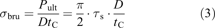
Figure 12 shows the effect of 0° layers’ combination percentage on bearing strength of X850 ± IM190 CFRP bolted joints. It is obvious that the 2% offset bearing strength increases with the increase of 0° layers’ combination percentage. For the higher 0° layers’ combination percentage case, the grouping of similarly 0° oriented plies leads to the generation of bigger fragments, which contributes to the formation of a pack of material and thus delivers the damage development on a more significant part of the specimen. 26 This leads to an earlier composite damage loss and lowers the 2% offset bearing strength. In contrast, the 0° layers’ combination percentage has no effect on ultimate bearing strength of bearing specimens with fastener fracturing. This can be explained through the use of equation (3).

Bearing strength of X850 ± IM190 CFRP bolted joints with different 0° layers’ combination percentages. CFRP: carbon fiber-reinforced polymer.
Effect of bolt diameter
Figure 13 shows the bearing stress–strain curves of X850 ± IM190 CFRP bolted joints with different bolt diameters. Joint configurations B1-9.53-C, B1-12.8-C, and B1-14.3-C with various bolt diameters—9.53, 12.8, and 14.3 mm—are chosen. All these joint configurations are damaged in bearing mode. When bolt diameter increases to 14.3 mm, the fastener in B1-14.3-C is found to be strong enough to withstand the tensile load. Thus, compared to the other two joint configurations, B1-14.3-C exhibits some residual load carrying capability on reaching the ultimate bearing strength as fastener fracture does not appear.
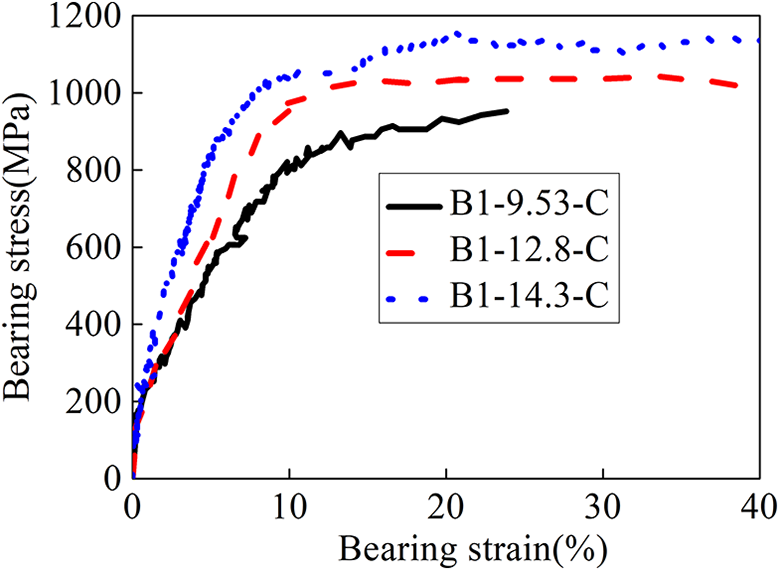
Bearing stress–strain curves of X850 ± IM190 CFRP bolted joints with different bolt diameters. CFRP: carbon fiber-reinforced polymer.
Figure 14 compares the joint stiffness of X850 ± IM190 CFRP bolted joints with different bolt diameters. It is observed that the joint stiffness increases in a nonlinear form with the increase of bolt diameter, which can be explained by equation (1).
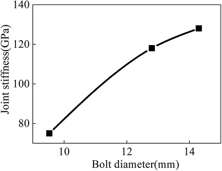
Joint stiffness of X850 ± IM190 CFRP bolted joints with different bolt diameters. CFRP: carbon fiber-reinforced polymer.
Figure 15 shows the bearing strength of X850 ± IM190 CFRP bolted joints with different diameters. When bolt diameter increases to 14.3 mm, the ultimate bearing strength of bearing specimen B1-14.3-C without fastener fracture cannot be determined by equation (3). The calculation method will be clearly explained in the section “Prediction of ultimate bearing strength.” It can be seen from Figure 15 that the bearing strength achieves a nonlinear increase with the increase of bolt diameter. This is similar to the observation in the literature. 27
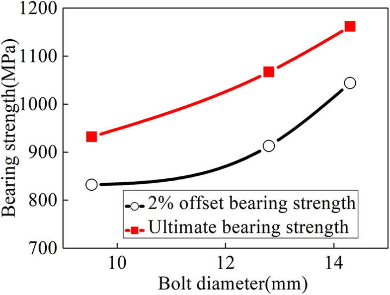
Bearing strength of X850 ± IM190 CFRP bolted joints with different bolt diameters. CFRP: carbon fiber-reinforced polymer.
Effect of curing method
Figure 16 shows the bearing stress–strain curves of X850 ± IM190 CFRP bolted joints with different curing methods. Joint configurations B1-12.8-C and B1-12.8-S manufactured with various curing methods—co-cured method and secondary bonding method—are selected. Both joint configurations are still damaged at the same load with a combination of bearing failure mode and fastener fracture. It can be seen from Figure 16 that the secondary bonding method lowers the joint stiffness and 2% offset bearing strength. The secondary bonding method not only causes thermal residual strains in the composite laminate but also degrades the mechanical property of composite material. 28 In terms of ultimate bearing strength, curing method has no effect on bearing specimens with fastener fracture. This can be explained by equation (3).

Bearing stress–strain curves of X850 ± IM190 CFRP bolted joints with different curing methods. CFRP: carbon fiber-reinforced polymer.
Figure 17 shows the microscopic fracture mechanism about co-cured and secondary bonding joint configurations. In the microstructure of co-cured specimen B1-12.8-C shown in Figure 17(a), the structural integrity of matrix material and the fiber/matrix bonding seem to be well maintained. On the other hand, the damage seems to be thoroughly intensified in the matrix and interfacial bonds of the secondary bonding specimen B1-12.8-S, as shown in Figure 17(b). When examining these micrographs, it is clearly evident that the matrix material has lost its mechanical properties due to the harsh thermal condition that the secondary bonding method produces. It is clear that laminates manufactured with co-cured method exhibit more excellent mechanical property than those manufactured with the secondary bonding method. Thus, it is suggested that the bolted joints should be assembled with laminates manufactured with co-cured method.

SEM micrographs of fracture surfaces related to (a) co-cured specimen B1-12.8-C and (b) secondary bonding specimen B1-12.8-S. SEM: scanning electron microscope.
Prediction of ultimate bearing strength
It is well-known that the load carrying capability of composite bolted joints is influenced not only by joint geometries, assembly factors, and laminate layup but also by the material property. Hart-Smith 15 developed a semianalytical approach to obtain the ultimate bearing strength of composite bolted joints in considering the above factors explicitly. As core of this method, SCRF C and tensile strength σ t of un-notched laminate are of the primary importance in predicting the ultimate bearing strength of mechanically fastened composite joints. Concern of this section is to determine the design parameters associated with X850 ± IM190 CFRP bolted joints:

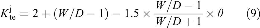
where the tensile strength σ t of un-notched laminate is closely related with the composite material property and ply ratio. The stress concentration factor (SCF) K bc corresponding to bearing stress of double-lap, single-bolt, composite joint is derived as follows:

Here, the parameter θ is expressed as follows:

Based on the literature, 15 the SCRF C is defined as follows:

where SCF

The empirical form of the elastic isotropic SCF
If the fastener is not strong enough to withstand the shear strength of bolted joint τ, as shown in equation (10), then the ultimate bearing strength σ bru should be calculated according to equation (2):

The analysis procedure to predict the ultimate bearing strength of integrated structure with semianalytical approach is schematically shown in Figure 18.
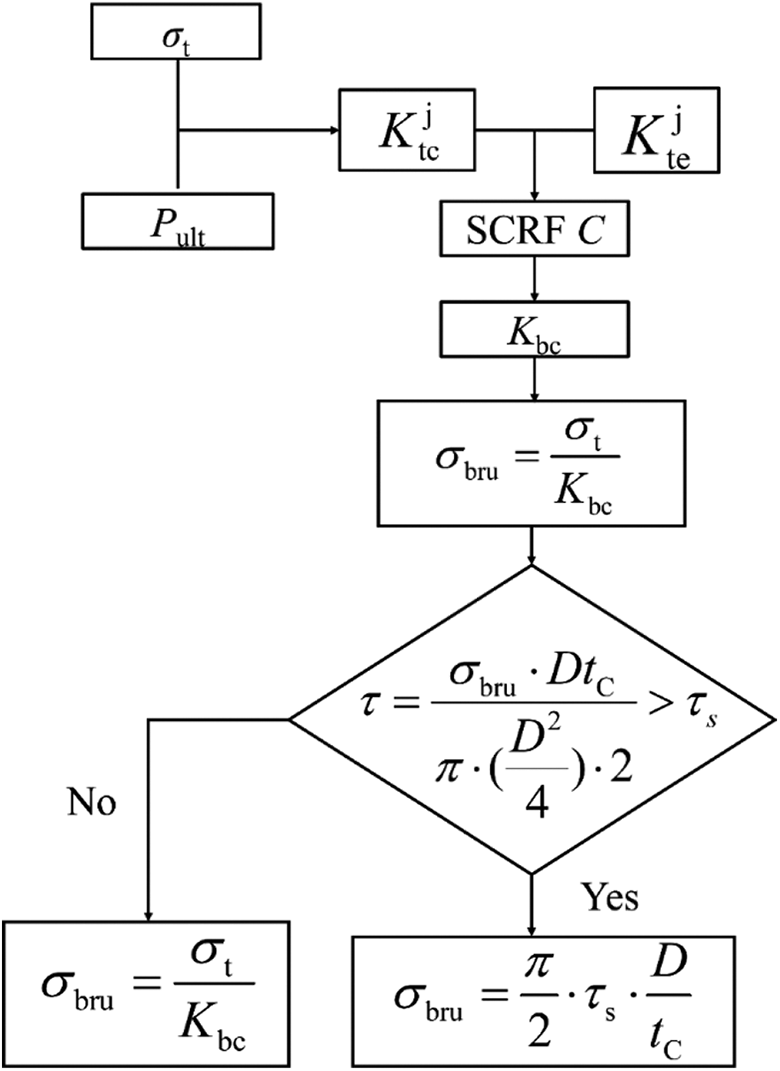
Failure analysis procedure of integrated structure with semianalytical approach.
According to the literature, 15 the prediction of SCRF C for mechanically composite joint is based on the assumption that the fastener is a rigid body. Since the final failure of most bearing specimens is characterized by fastener fracture, the SCRF C cannot be obtained with the use of the existing test data. Double-lap, single-bolt, composite-titanium joints with the aforementioned four different ply ratios are chosen for the determination of SCRF C: ((0°)25%/(±45°)50%/(90°)25%), ((0°)30%/(±45°)60%/(90°)10%), ((0°)50%/(±45°)40%/(90°)10%), and ((0°)70%/(±45°)20%/(90°)10%), representing stacking sequences of (45°/0°/−45°/90°)5 s, (45°/0°/−45°/0°/45°/90°/−45°/0°/45°/−45°)2 s, (45°/0°/−45°/0°/90°/0°/45°/0°/−45°/0°)2 s, and (45°/0°/0°/−45°/0°/0°/0°/90°/0°/0°)2 s, respectively. For these joint configurations, the geometries are required: L = 230 mm, W = 60 mm, D = 11.11 mm, e = 35 mm, t = 7.52 mm, t T = 3.8 mm, and g = 114 mm. Meanwhile, composite laminates with the corresponding stacking sequences are employed to obtain the tensile strength σ t of the un-notched laminate. For these un-notched laminates, the geometries are designed: L = 230 mm, W = 60 mm, and t = 7.52 mm. The ultimate failure load P ult of mechanically fastened composite joint, tensile strength σ t of un-notched laminate, and SCRF C is summarized in Table 4.
Design parameters for X850 ± IM190 CFRP bolted joints.

CFRP: carbon fiber-reinforced polymer.
Table 5 lists the ultimate bearing strength σ bru of double-lap, single-bolt joint in X850 ± IM190 CFRP composites investigated by experimental and semianalytical methods. It can be seen that the semianalytical results give a close correlation with the experimental analysis, with less than 3% maximum error. This error is due to that the microcosmic manufacture defects in the X850 ± IM190 CFRP bolted joints are not considered in the semianalytical method. Despite of this particular aspect, the results still demonstrate that the obtained design parameters, tensile strength σ t of un-notched laminate, and SCRF C can provide technological support for the strength prediction of X850 ± IM190 CFRP bolted joints. In addition, the prediction of ultimate bearing strength for B1-12.8-S is not given in Table 5. This is because the above section suggests that the bolted joints should be assembled with laminates manufactured with co-cured method, it is unnecessary to test the design parameters for laminates manufactured with the secondary bonding method.
Ultimate bearing strength prediction by experimental and semianalytical methods.

Conclusion
Bearing performance of X850 ± IM190 CFRP bolted joints was investigated experimentally. The effects of ply ratio, 0° layers’ combination percentage, bolt diameter, and curing method were considered. Moreover, an efficient semianalytical approach was established to predict the ultimate bearing strength of the joint configurations. The following conclusions can be made: The presence of 0° ply ratio is important in maximizing the joint stiffness. Introducing ±45° ply ratio is important to maximize the 2% offset bearing strength and delay the occurrence of bearing failure. The higher variation of 0° layers’ combination percentage causes the damage area to become more globalized and reduces the 2% offset bearing strength, though it has a minimal effect on the joint stiffness. Increasing the bolt diameter increases the load carrying capability of joint configurations. This has a positive effect on joint stiffness, 2% offset bearing strength, and ultimate bearing strength. Secondary bonding method causes higher residual stress in laminate. This has a negative effect on joint stiffness and 2% offset bearing strength. It is suggested that the joint should be assembled by the co-cured laminates. In test, the fastener in bearing-failed joint configurations except for B1-14.3-C is found not to be strong enough to withstand the tensile load. Thus, fastener fracture occurs, which lowers the joining efficiency. In this situation, the ultimate bearing strength of composite bolted joints depends on the shear strength of the fastener and bolt diameter/laminate thickness ratio. The semianalytical approach is shown to give close agreement with the experimental results in terms of ultimate bearing strength. This demonstrates that the obtained design parameters, tensile strength of un-notched laminate, and SCRF are helpful for predicting the load carrying capability of X850 ± IM190 CFRP bolted joints. The proposed test with only one bolt is of high interest but very anachronistic, unrealistic, and without relation to real construction and application. Thus, additional research of multibolt joints will be taken into account for future tests because they are the most commonly used form of mechanical joints in aircraft structures.
Footnotes
Declaration of conflicting interests
The author(s) declared no potential conflicts of interest with respect to the research, authorship, and/or publication of this article.
Funding
The author(s) disclosed receipt of the following financial support for the research, authorship, and/or publication of this article: This work is supported by the State Key Laboratory for Strength and Vibration of Mechanical Structures under grant No.SV3029-KF-12, the Education Department of Guangxi Zhuang Autonomous Region under grant no. 2019KY0365, and the Science and Technology Department of Guangxi Zhuang Autonomous Region under grant no. AD19110150.