
Abstract
The present article discusses the influence of delamination and external loads on the heat transfer in flat and curved laminated panels. Three cases are considered in details: (1) the unloaded structure (length is a constant), (2) the static loading, and (3) the fatigue loading. Here, the comparison between experimental and numerical (finite element method) results is presented. The numerical model allows us to adopt implementations of various boundary conditions as well as the size of delamination. The influence of the shallowness parameter and the thermal resistance is demonstrated. The experimental detection of temperature contours during the cooling process has been conducted at different points in the area surrounding the delamination.
Introduction
Nondestructive evaluation (NDE) offers an ideal, cost-effective solution for a wide range of in-service and manufacturing composites applications.
1
–6
It is fast, noncontact, can be single-sided, and offers wide area coverage of flat or curved parts. A lot of NDE techniques have been developed, such as ultrasound, acoustic emission, thermography, Eddy current, tomography, penetrant testing, or charge-coupled device (CCD) camera.
7
Some relevant information, comparisons, and applications can be found, for example, in literature.
8
–12
Considering composite materials, NDE is applied in the detection of delaminations, impact damage, water entrapment, inclusions, density variations, and evaluation of adhesive bonds.
13
–16
Thermographic NDE (TNDE) systems range from a simple infrared (IR) camera combinations to fully automated inspection systems capable of thickness or defect measurement and advanced materials characterization.
17,18
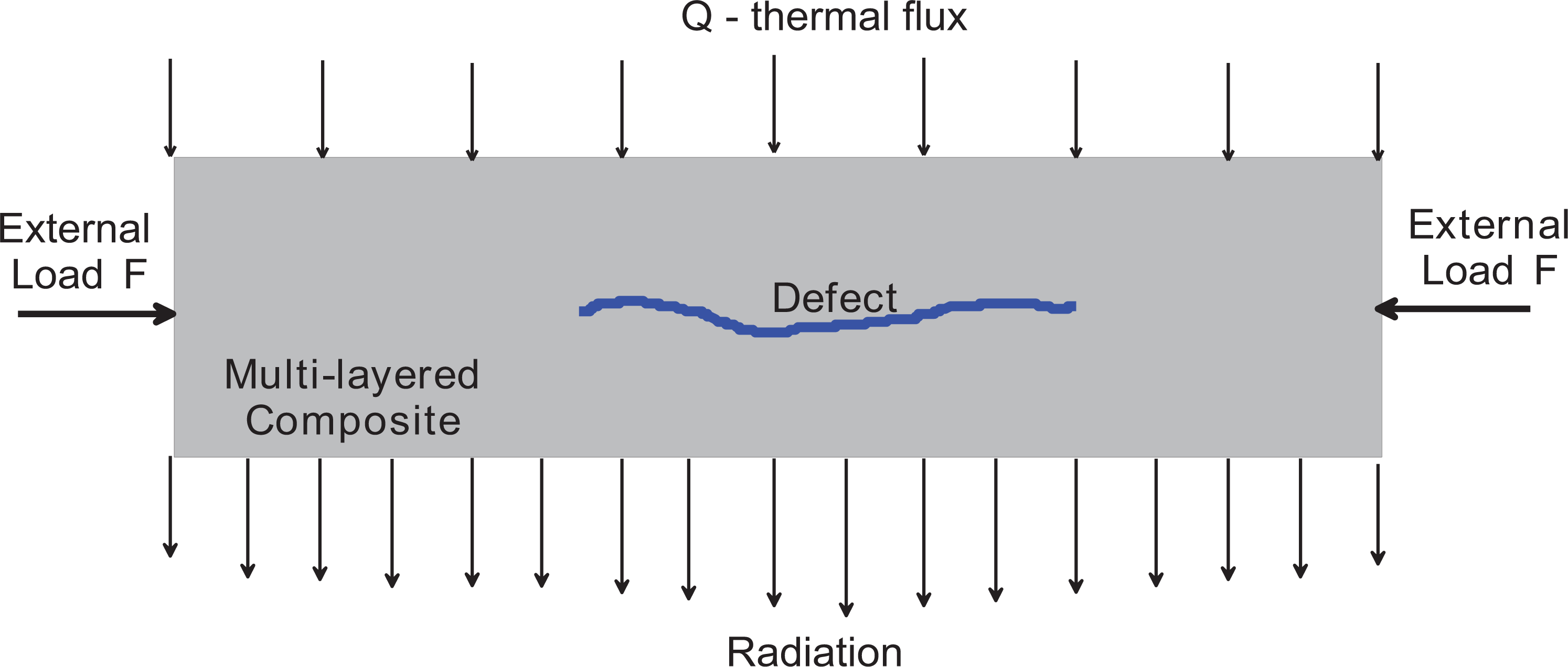
In TNDE, a surface of the component under test is actively heated, and the subsequent surface temperature response of the part to the stimulation is monitored with an IR camera. Although there are many possible configurations for TNDE (e.g. thermal treatment, cooling stimulation, and step or modulated heating, to name a few), the same basic principles apply. The physical process can be reduced to three steps in which energy is converted to various forms: The surface of the component is uniformly heated. Typically, this is accomplished using light, although forced air, steam, hot water, electrical current, electromagnetic induction, and acoustic energy have been demonstrated for particular applications. During the diffusion of the heat from the top of the sample toward the interior having a lower temperature, the top surface temperature decreases. However, the dissimilar rate of cooling between regions of the top surface placed above the subsurface discontinuities (defects) in comparison to intact regions is observed. Figure 1 graphically depicts this scenario for the region with a subsurface defect. The radiation of the top surface is monitored through a thermographic camera. It allows for presentation of the images of temperature distribution on the component surface. The anomalous areas appearing on the thermal images during cooling indicate the subsurface discontinuities.
Increased infrared radiation at the surface below a defect.
The form of the radiation is sensitive to the existence and values of external loads acting on the structure that may be static or variable (dynamic or fatigue problems). In addition, the existence of the nonzero force may result in the appearance of the additional defects.
The aim of the present article is to discuss the influence of delaminations and external compressive loads on heat transfer for flat and curved laminated panels. The analysis is carried out both theoretically and experimentally.
Theoretical formulation
The response of composite parts monitored by the IR camera depends on the various properties of its components, such as thermal (conductivity, diffusivity, effusivity, and specific heat), spectral (emissivity, absorption, and reflection), and others (porosity and density). 16 During thermographic analysis, all properties mentioned above are important, especially when a sample has inside defects in the form of voids, pores, or delaminations. In defected areas lowering of density and thermal conductivity is observed, and also the thermal diffusivity is different, what finally influences on heat transfer within the material. 13,19,20
Diffusivity α (m2 s−1) is given by

where k is the thermal conductivity (W m−1 K−1), ρ is the density (kg m−3), and Cp is the specific heat capacity (J kg−1 K−1).
The Fourier relation of heat transfer by conduction is given by

where ∇T is the temperature gradient (K m−1) and
In Figure 1, the 1-D case of heat diffusion in a material having a defect is presented. The applied boundary conditions are as follows: (a) on the top surface: the uniformly distributed heat flux and (b) on the bottom surface: adiabatic boundary condition. The increase of temperature through the thickness of the sample is defined as follows 21,22 :
where h is the plate thickness, Q is the heat flux, t is the time, and ierfc is the first integral of the complementary error function. 22
In the current studies, we consider the glass/epoxy laminates for which the thermal diffusivity α is low. According to equation (3), for low thermal diffusivity, ierfc function approaches to zero and temperature rise is as follows:

The increase in temperature is linearly associated with the square of the time t. In the thermal image of the defected area, the temperature increase deviates from the intact area. The resulting global conductivity components for the multilayered laminates are as follows 23 :

For orthotropic structures, the heat conduction coefficient in the local fiber coordinated system is represented by the matrix:

Table 1 presents the material properties of glass/epoxy composite and Teflon (defect) used in the thermal analysis.
Material properties of the model components. 22

If the analyzed composite structure is loaded by the force F and the heat flux Q (Figure 1), the Fourier’s relation (equation (2)) is supplemented by elastic relations that can be expressed in the following form:

where
Results
Numerical results
Krishnapillai et al. 24,25 discussed the problem of 3-D finite element (FE) thermal modeling, which takes into account aspects being not considered in 1-D and/or 2-D approaches. They indicated that the significance of such differences is sometimes not obvious for subsurface defects of flat panel composites. However, the problem becomes essential in the modeling of thermal behavior in complex components. The numerical analysis is conducted to predict the heat flow, the temperature distributions across the thickness of the laminated composite, and the stress and strain distributions in thermomechanical loading (Figure 1).
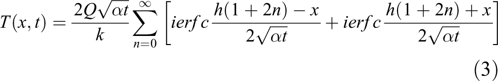
The composite panel is made of eight-layered cross-ply (0°/90°) antisymmetric glass/epoxy laminate. It is assumed that the single square delamination is located in the middle of the composite panel with respect to all coordinates (Figure 2). The artificial delamination is inserted between the fourth and the fifth play. The following notations are used: L, D, and f are the length, the width, and the high of the composite panel, respectively, and a represents both the length and width of the Teflon insert.
The geometry of the composite structure with the square delamination and cross-section in the defected area with the stacking sequence.
The numerical analysis is carried out with the use of the FE package NISA II v.17. The numerical FE studies employ 3-D solid FE having 20 nodes (NISA-NKTP4) to characterize the behavior of the composite structure. The numerical model consists of eight layers of FEs according to the assumed stacking sequence. The preliminary convergence tests have been applied to obtain the accurate numerical result. To model the delamination, the nonmerged nodes between neighboring plies (i.e. between fourth and the fifth lamina) on the defective area were used. The composite panel is characterized by the following set of dimensionless geometrical parameters: D/L, f/D, a/L, whereas the thickness ratio h/L (the panel thickness to the panel length) is constant and equal to 2/300 and the thickness of the Teflon insert varies of 0.2, 0.7, and 1.2 (mm).
Numerical results are presented with the use of the dimensionless time and temperature that were introduced by Maillet et al. 26 :

The heat conduction of composite structures and the Teflon insert are characterized by the thermal resistance R defined as follows:

where kxx denotes the global conductivity evaluated with the use of the relation (equation (5)). Let us note that the composite cross-ply structure considered resembles quasi-isotropic one. The influence of the shallowness parameter f/D (Figure 2) and the thermal resistance R is shown in Figure 3.

The influence of the shallowness parameter f/D and the thermal resistance R.
Presented results show visible differences in the thermal behavior of flat and curved composite structures what is crucial in damage detection by the pulse thermography method. Thus, the experimental validation is crucial from the efficiency of damage detection method point of view.
Experimental procedure and results
The system used in this trial has two flash lamps, which are mounted within a hood along with a FLIR 325 camera. The flash lamps are triggered after which the camera records a series of thermal images of the surface. These data are then processed with the use of the IRNDT system to facilitate review with a suite of sophisticated analysis tools. The applied experimental setup for thermographic and mechanical tests is shown in Figure 4. The analysis was carried out under various loading condition since the cylindrical panel was uniformly compressed to investigate the possible opening of the delaminated area.

Experimental setup for thermographic and mechanical tests.
The material studied was a composite woven roving glass/epoxy resin. Four material constants describe the elastic behavior of the composite material, that is, Young’s moduli E1 = E2 = 62 (GPa), Poisson’s ratio ν = 0.26, and Kirchhoff’s modulus G12 = 7.8 (GPa).
In the thermographic analysis, the pulse phase thermography was used. In this technique, the composite sample is rapidly heated, and the heat decay is observed on the surface of heating or the opposite side using a thermographic camera. The interruptions in the regular heat transfer are detected by the camera and presented as a contrast to the regular thermal flow. 25 The detection of the temperature differences was observed at two points P1 and P2 (with and without delamination, respectively). The first objective in this study was to make a correlation between the changes in the temperature of specimen and the thicknesses of Teflon inserts. The samples with the Teflon inserts having the thicknesses of 0.2, 0.7, and 1.2 (mm) were analyzed. In all cases, the artificial delamination was inserted between the fourth and the fifth play in the middle of the panel. Figure 5 demonstrates the distribution of the temperature with time at two points. The heated surface is localized in the delaminated area. As it is shown in Figure 6, the thermal resistance of the composite structures decreases with the increase of the thickness of the Teflon inserts.

Variations of temperature during cooling for areas with and without delamination.
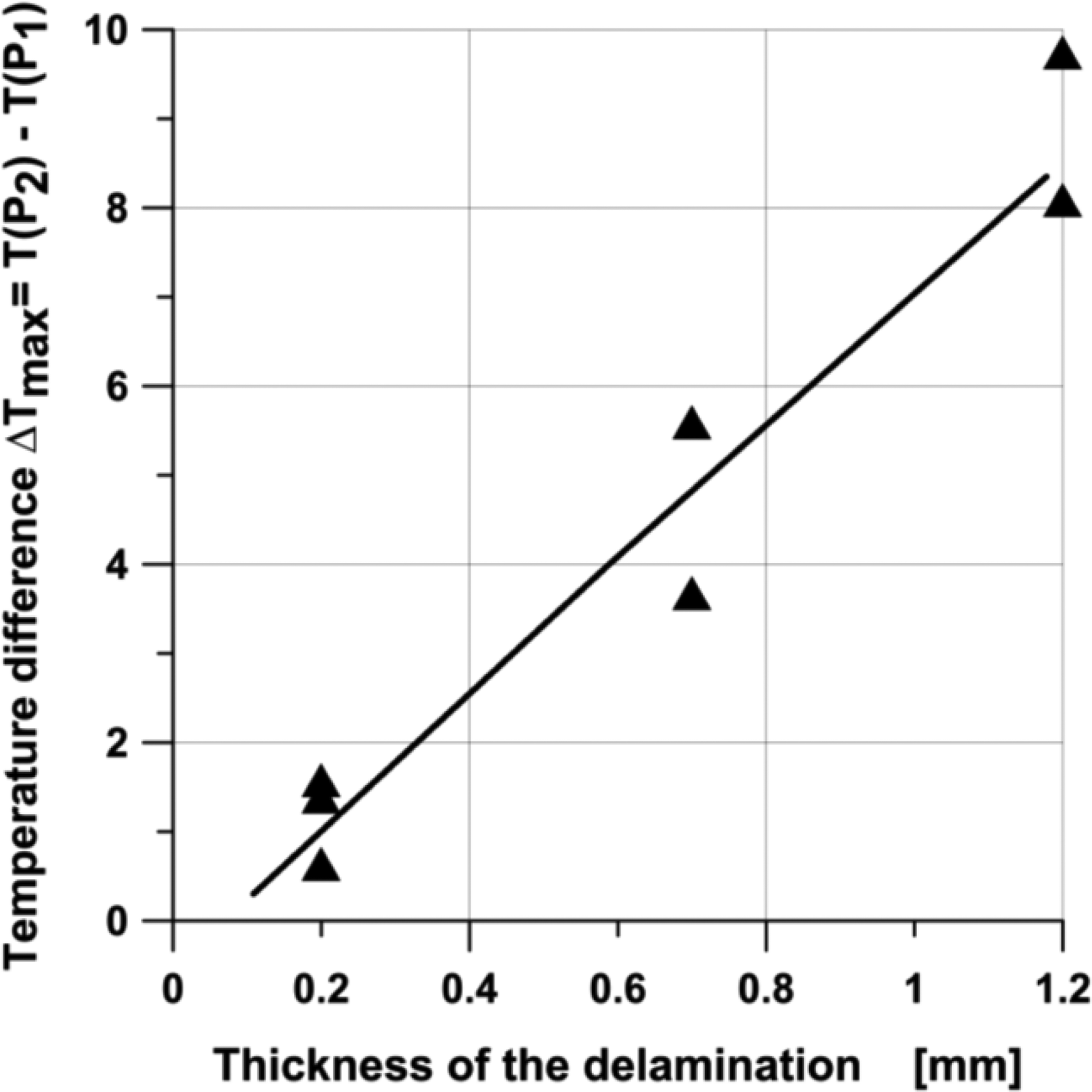
Differences of temperature calculated for various thicknesses of delaminations (points P1 and P2 represent with and without delamination, respectively).
Static and fatigue compressive loads
The identical effects to those plotted in Figures 5 and 6 were observed for different values of the compressive forces but prior to the final failure of the laminated structures that took the form of classical cracks but proceeded by the global buckling of the cylindrical panel. 27 Independent of the thickness of defect (Teflon insert), no changes in the area connected with delamination were observed up to the final failure. We did not experience any opening of delamination during experimental tests. The issue of composite structures with delamination has been analyzed and discussed by Muc, since 1995, 28,29 and Muc et al. 3 –5,11,12 Recently, we have presented our studies on the opening of delamination in multilayered structures. 30
A pulsed thermographic system was used not only to image the defects but also to present their evolution under the various loading conditions. Increasing the value of the compressive load, the variations of the temperature were also detected. As may be seen in Figure 7, the distributions of the temperature increase with the increase of the damage. The temperature variations are presented for different loading values represented by the displacements of the upper plate (see Figure 4), that is, 0.250, 1.955, and 2.980 (mm).

Temperature profiles at the point of damage (crack).
The surface temperature was also registered during fatigue investigation to obtain information on damage development in the analyzed sample. The damage evolution observed both as the deterioration of the axial stiffness and temperature increase is plotted in Figure 8. The increase in the temperature is associated with the growth of the number of cycles. The similar effects were reported in literature. 31,32

Temperature contrast (T–T0) and normalized axial stiffness (E(N)/E(N = 0)) profiles versus normalized number of cycles (N/Nf).
Conclusions
The goal of the present article was to determine the influence of internal, artificial defects, and external compressive loads on heat transfer for cylindrical laminated panels. The analysis was conducted both theoretically and experimentally. The influence of the thermal and geometrical parameters to the temperature distribution related to the dimensionless time was determined with the use of numerical FE model. Experimental analysis shows the differences in the thermal distribution in the intact and defected structures. The delamination thickness has a significant influence on the temperature value in the defected area. Thus, the pulse thermography method can also be applied in the precise identification of the detected damage what is especially important in the structures subjected to fatigue loading conditions. The identification of the defect connected with the permanent monitoring of the analyzed structure can be applied in the assessment of the stiffness reduction and fatigue life of the composite elements.
Footnotes
Acknowledgement
The authors would like to acknowledge P. Pastuszak for testing support.
Declaration of conflicting interests
The author(s) declared no potential conflicts of interest with respect to the research, authorship, and/or publication of this article.
Funding
The author(s) received no financial support for the research, authorship, and/or publication of this article.