
Abstract
HfC-SiC protective coating was deposited on the surface of SiC-coated carbon/carbon composites by supersonic atmospheric plasma spraying due to the high arc temperature and the efficient deposition rate. The morphology and microstructure of the HfC-SiC coating were analyzed by X-ray diffraction and scanning electron microscopy. The results showed that Hf and Si elements distributed uniformly in the coating and the coating was dense without crack. Ablation resistance test was processed by oxyacetylene torch. During the ablation process, the sintering rate of HfO2 was slow, and more oxygen diffused into the internal coating, which caused the oxidation of the internal coating and damaged the structure of internal coating in the ablation center region. In addition, during cooling process, a new phase HfSiO4 was generated by the reaction between HfO2 and SiO2, which acted as a pinning agent to prevent the further expansion of the crack.
Introduction
Carbon/carbon (C/C) composites are thought to be one of the most promising materials in the field of aeronautics and astronautics. 1 However, the applications in oxidation environment are limited because of its poor oxidation resistance. C/C composites could be oxidized and destroyed rapidly at above 723 K. 2 In order to overcome the disadvantages, until now, various kinds of coatings have been used to protect the C/C composites from being oxidized. 3 –5 Based on the high melting point, good thermal shock, and oxidation resistance, ultra-high temperature ceramics (UHTCs) such as HfC, HfB2, ZrC, and ZrB2 are attracted more and more interest, and some refractory carbides and borides have been successfully applied in protecting C/C composites in high-temperature oxidation environment. 6 –11 Among the several UHTCs, HfC was considered to be one of the most promising materials in the application of coating technique. HfC has a high melting point over 4100 K, and the oxidation product HfO2 has high melting point over 3100 K. Besides, HfC has the high thermostability and good resistance to ablation, which indicates HfC can protect C/C composites against oxidation efficiently at high temperature. 12,13
Supersonic atmospheric plasma spraying (SAPS) is considered to be an effective method to deposit UHTCs coatings on different substrates, due to the high temperature of plasma arc, high velocity of spraying particle, and high deposition rate. 14,15 The temperature of plasma arc is about 10,000 K and velocity of particle is up to 600 m/s, which can be used to prepare oxidation protective coating efficiently. The sprayed coatings have dense structure and good bonding with the substrates, which indicates the brilliant applications in protective coatings. 16 –18 The as-prepared coatings can be used to protect the C/C composites from ablation in oxidation environment efficiently, which could be applied to the field of aeronautics and astronautics. Zhou et al. 19 prepared Fe48Cr15Mo14C15B6Y2 amorphous coatings by SAPS and investigated the effects of the Ar flow rate and spraying power on the microstructures and amorphous phase contents of Fe-based metallic. Guo et al. 20 deposited Tungsten coating on SiC-coated C/C composites by SAPS and tested the ablation resistance of the coating. The results showed that W coating could protect substrate above 60 s under heat flux of 2400 kW/m2.
In this work, firstly, a SiC bonding layer was prepared on the surface of the C/C composites, which can relieve the mismatch of the coefficient of the thermal expansion (CTE) between the HfC-SiC coating and the substrate. 21 And then, the HfC-SiC was deposited on the surface of SiC coating by SAPS in air. The ablation resistance of the HfC-SiC coating was tested by an oxyacetylene torch. The ablation mechanism and morphology evolution of the HfC-SiC coating after ablation for different time were also analyzed.
Experimental
Preparation of HfC-SiC coating for SiC-coated C/C composites
2-D C/C composites with a density of 1.7 g/cm3 served as a substrate (Φ 30 mm × 10 mm). A SiC bonding layer was deposited on the surface of the substrate. The preparation process has been reported. 22 The HfC-SiC coating was prepared on the surface of the as-prepared sample by SAPS in air. The mixtures of 80 vol% HfC and 20 vol% SiC powders pelleted by spray dryer were used as precursor. The purity of the various particles are 99.9%. The technological parameters of the whole preparation process were listed in the previous paper. 23
Ablation test and microstructure analysis
The oxyacetylene ablation torch was used to test the ablation behavior of the as-prepared samples. The pressure and flux of C2H2 were 0.095 MPa and 0.65 m3/h, and those of O2 were 0.4 MPa and 0.88 m3/h, respectively. The heat flux was about 2.38 mW/m2. The surface temperature of the HfC-SiC coating was measured by an infrared thermometer (MR1SCSF, Raytek, USA). The samples were exposed to the flame for different time. The linear ablation rate (Rl ) and mass ablation rate (Rm ) of the samples were obtained according to the following equations:


Δl and Δm are the change of thickness and mass before and after ablation, respectively. The t is the ablation time.
The crystalline structure and morphology of the as-obtained coatings and ablated coatings were investigated by X-ray diffraction (XRD, X’Pert Pro, PANalytical, Almelo, the Netherlands), scanning electron microscopy (SEM, JSM6460, JEOL Ltd, Mitaka, Japan) along with an energy-dispersive spectroscopy (EDS, Oxford INCA).
Results and discussion
Microstructure of HfC-SiC precursor
Figure 1(a) shows the microstructure of the HfC-SiC precursor, which was pelleted by spray dryer. It can be observed that the particle is in the shape of spherical and the diameter of the particle is about 50 µm. In addition, on the basis of the EDS analysis, as shown in Figure 1(b), it can be seen that the flake-like SiC was encased by granular HfC, which can make sure the fluidity of the mixed particles.
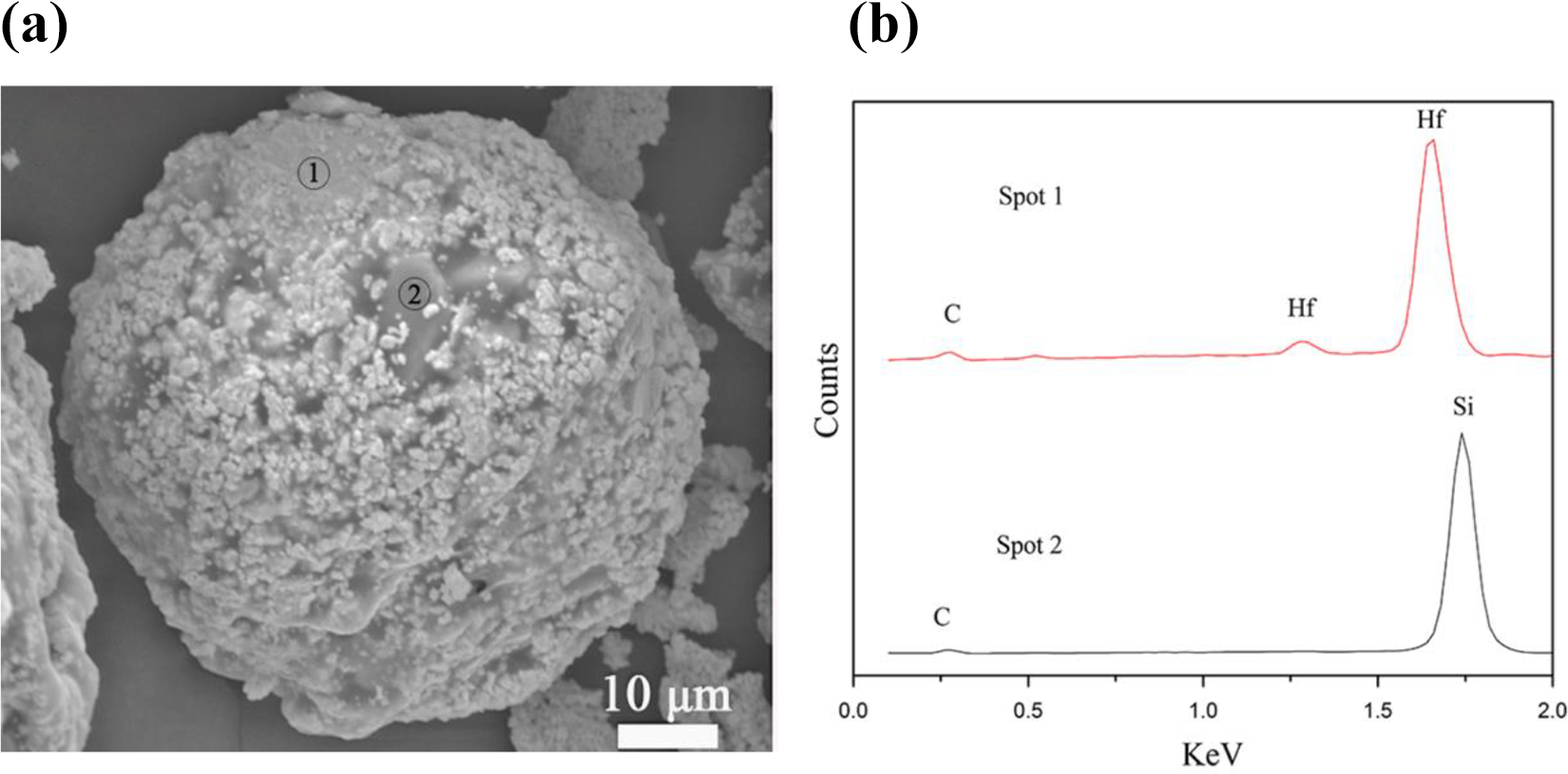
SEM images and EDS analysis of the precursor powders: (a) microstructure of precursor powder and (b) EDS of spot 1 and spot 2. SEM: scanning electron microscopy; EDS: energy-dispersive spectroscopy.
Morphology and microstructure of HfC-SiC coating
HfC-SiC coating was deposited on the surface of SiC-coated C/C composites by SAPS in the atmospheric environment. Figure 2 shows the XRD patterns of the HfC-SiC powders and HfC-SiC coating. From the XRD patterns, it can be seen that the diffraction peaks are the standard diffraction peaks of HfC and SiC before spraying, which are in accord with the Joint Committee on Powder Diffraction Standards (JCPDS) card no. 03-065-0964 and no. 00-040-1173. Whereas the detected diffraction peaks were altered after spraying, which was due to the oxidation of the carbides during the spraying process. Some of the HfC and SiC powders were oxidized to HfO2 and SiO2, respectively. During the spraying process, the HfC particles melted quickly due to the high temperature. SiC would decompose at the temperature above 3000 K, however, due to the short heating time in the nozzle and high spraying velocity, only a little SiC decomposed during the spraying process. The residual SiC particles sintered with the fused HfC and then solidified on the surface of the samples, which formed the protective coating. Additionally, because of the short heating time in the nozzle, HfC and SiC did not generate the solid solution, which could be proved by the XRD patterns.
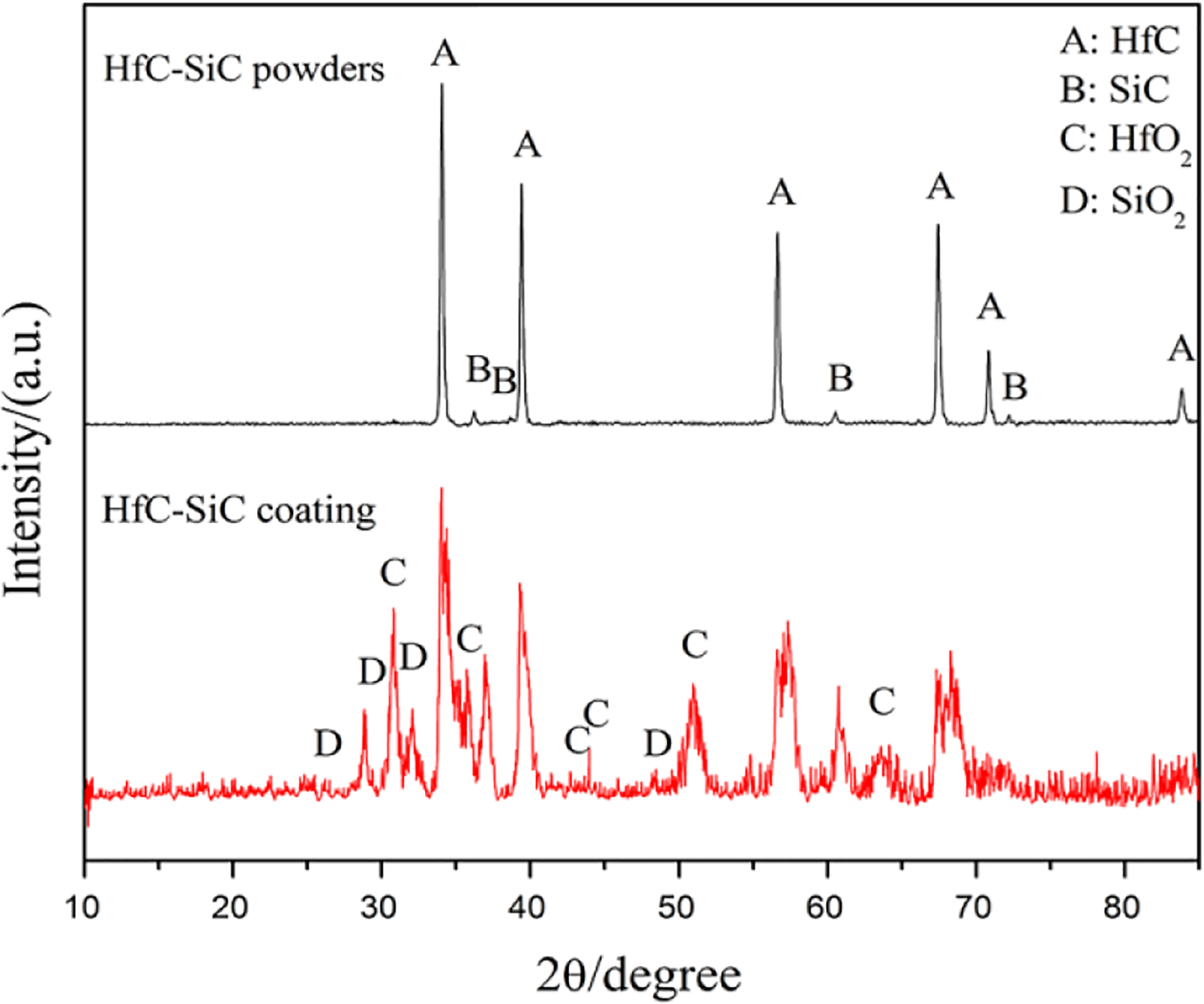
XRD patterns of HfC-SiC powders and HfC-SiC coating. XRD: X-ray diffraction.
Figure 3 shows the surface morphology of the deposited HfC-SiC coating. According to the surface morphology, it can be seen that the coating is dense and rough without crack. In addition, it is also observed that the coating surface is mainly composed of fully molten area and insufficient molten area. The fully molten area is mainly composed of melted particles, which were completely fused in the high-temperature environment during spraying, and no pinhole was found on the fully molten area. Though the temperature was over the melting point of the HfC particles, due to the short heating time in the nozzle, some HfC powders fell to melt and stacked up on the surface of the sample leading to the insufficient molten area and the porous structure. Additionally, the high-temperature carbides were oxidized and generated some gases, which evaporated from the inner coating and led to the pinholes. It can be noticed that a lot of pinholes are distributed on the insufficient molten area. Whereas during spraying, some oxides such as HfO2 and SiO2 were generated on account of the oxidation environment, whose melting points were relatively low. 13 The oxides were easier to melt and contribute to seal some formed pinholes.

Surface SEM images of the HfC-SiC coating: (a) surface morphology of the sample and (b) high magnification of (a). SEM: scanning electron microscopy.
The cross-sectional micrographs of the HfC-SiC coating are shown in Figure 4(a). It can be seen that the internal layer is the SiC coating prepared by pack cementation, which plays a role in relieving the mismatch of coefficient of thermal expansion between C/C composites and HfC-SiC coating. 21 The outer layer is HfC-SiC coating deposited by SAPS. The interface between external HfC-SiC coating and internal SiC coating is clear, which indicates that the combination between the two coatings is mechanical bonding. Additionally, the interface (marked by red dash dot) is fluctuant, which was caused by the rough surface of the internal SiC coating. The structure of HfC-SiC coating is complete and the thickness is about 150 µm. Meanwhile, in accordance with Figure 4(b), the high magnification of spot A in Figure 4(a), it can be observed that no pinhole and crack can be found in the coating, which means the coating structure is dense. In addition, the pinholes on the surface are nonpenetrating, the reason is the preformed pinholes caused by the unmelted particles would be sealed by the following unmelted or melted particles during spraying. On the basis of the element map analysis, as shown in Figure 4(c) and (d), it can be seen that the Hf and Si elements are distributed uniformly in the HfC-SiC coating, which indicates the whole coating has the same physical and chemical properties.

Cross-sectional micrographs and elements map analysis of the HfC-SiC coating: (a) cross-sectional micrographs of the sample, (b) high magnification of (a), (c) Hf element, and (d) Si element.
Ablation property of HfC-SiC coating
The ablation property of HfC-SiC coating was tested with an oxyacetylene torch. The prepared samples were exposed to the torch for 30 s, 60 s, 90 s, and 120 s, respectively. Meanwhile, the surface temperature variation of the coating was recorded by an infrared thermometer. As shown in Figure 5, it can be seen that the surface temperature rose fast within the first 30 s and reached at 2200 K. Then the surface temperature remained about 2350 K during the last ablation time. Compared to the HfC coating, 24 the surface temperature reduced obviously due to the evaporation of SiO2.
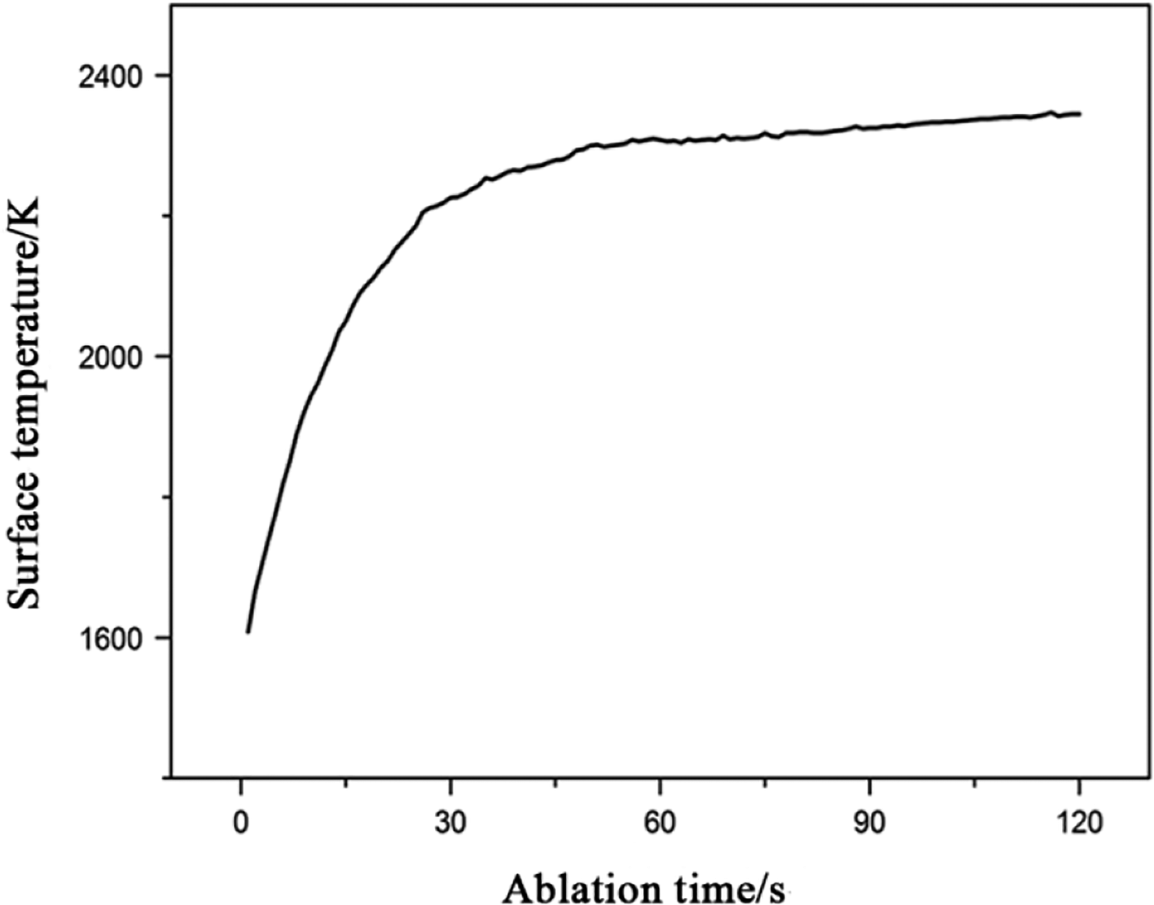
Surface temperature variation of the HfC-SiC coating during ablation.
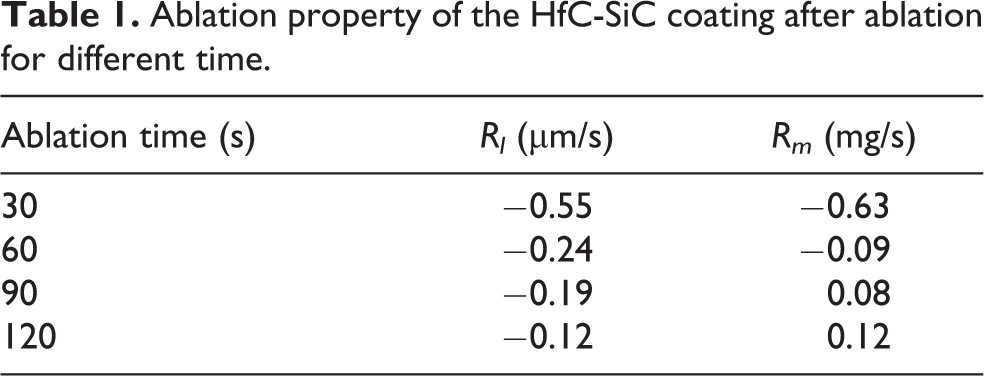
The linear ablation rate and mass ablation rate of HfC-SiC coatings are listed in Table 1. It can be seen that the linear ablation rate increases with the ablation going on, but the linear ablation rate is still negative, which indicates that the thickness of the coating increased gradually during ablation, whereas the increase slowed down along with the ablation. After ablation for 120 s, the linear ablation rate of the sample is −0.12 µm/s. In addition, the mass ablation rate of the samples also increases combined with the ablation time. After ablation for 90 s, the ablation rate changes from negative to positive, which means the weight of the sample increases first and then decreases. After ablation for 120 s, the mass ablation rate of the sample is 0.12 mg/s.
Ablation property of the HfC-SiC coating after ablation for different time.
The surface of the coating underwent violent chemical reactions, and the carbides were oxidized during the ablation. Figure 6 shows the XRD patterns of the HfC-SiC coatings after ablation for different time. According to the diffraction peaks, it can be seen that the main products are the HfO2 phase, which is in accordance with JCPDS card no. 00-006-0318. Meanwhile, some diffraction peaks of SiO2 and HfSiO4 are also detected. During the ablation progress, all of the oxidization reactions were set off in an oxygen-rich environment, and the following reactions may take place:


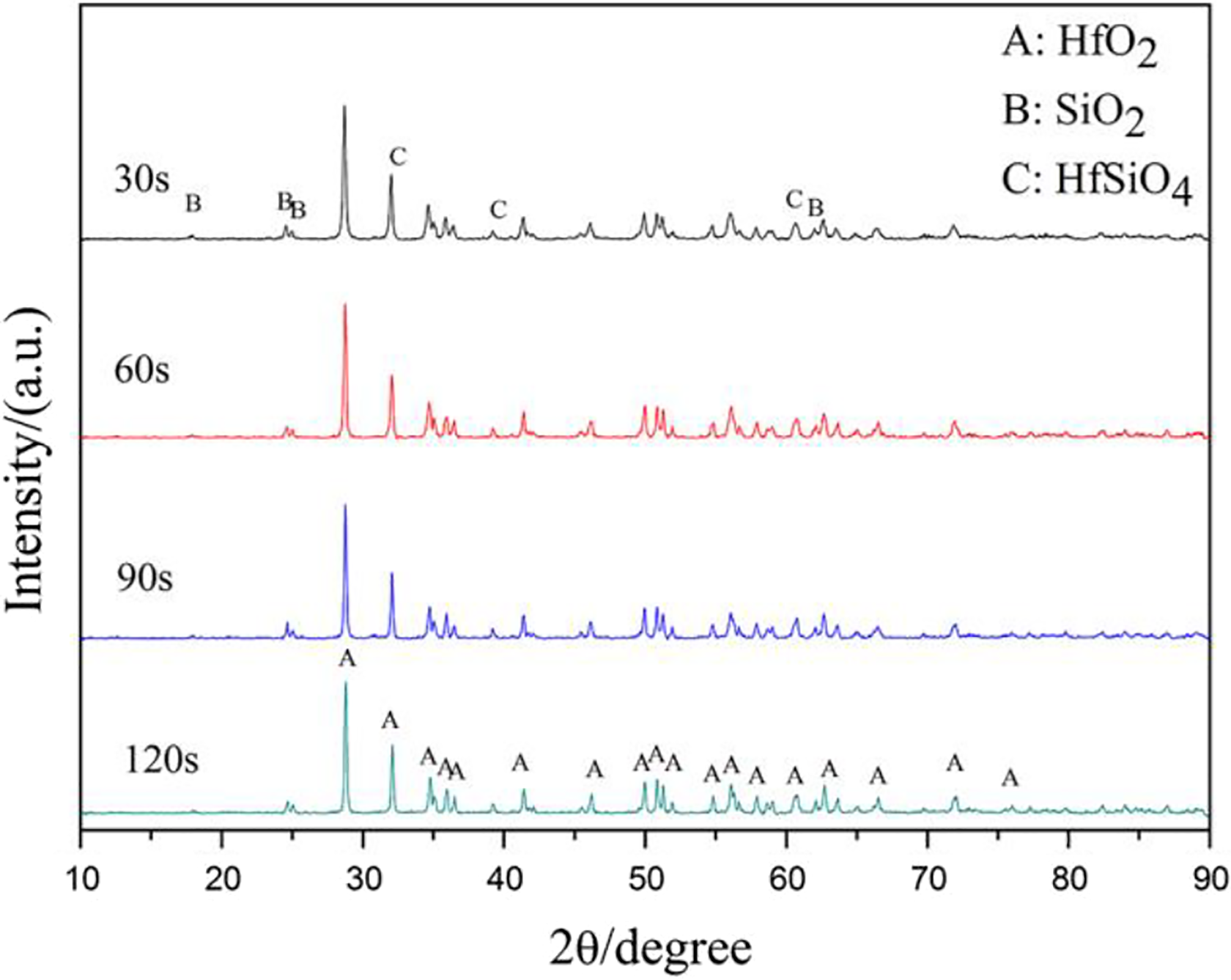
XRD patterns of the HfC-SiC coatings after ablation for different time. XRD: X-ray diffraction.
With the ablation going on, the intensity of the HfO2 peaks became stronger, indicating more HfC phases were oxidized; while that of the SiO2 peaks became weaker, which was resulted from the low melting point and evaporation of SiO2. 25 The changes of the Gibbs free energy of equations (3) and (4) are −818.32 KJ/mol−1 and −764.13 KJ/mol−1 at 2350 K, respectively, which were calculated by FactSage software. The changes of the Gibbs free energy were negative, indicating the reactions could occur during ablation. Additionally, according to the binary phase diagrams of HfO2-SiO2, 26 the HfSiO4 is generated below 2030 K, which meant the equation (5) took place during the cooling process.
Ablation morphology
The macrographs of different samples after ablation are presented in Figure 7. As displayed in Figure 7, the coatings kept integrity without desquamation, and no crack was found on the surface after ablation for different time, which meant a good bonding between the external HfC-SiC coating and internal SiC coating. The ablation region (labeled by red circular in Figure 7) extended continually and the oxidation of the center region enlarged gradually with the ablation going on. During ablation, the heat generated by oxyacetylene and reactions, and oxygen transferred along the coating surface, resulting in the formation and expansion of the oxidation region.

Macrographs of the HfC-SiC coatings after ablation for different time: (a) 30 s, (b) 60 s, (c) 90 s, and (d) 120 s.
After ablation for different time, the surface micromorphology of the HfC-SiC coatings in the ablation center region is displayed in Figure 8. After ablation for 30 s, according to the Figure 8(a), it is noted that the coating surface is composed of granular particles, which stack together forming the loose and porous structure. Meanwhile, no crack but some pores is found on the coating surface. In accordance with spot EDS analysis, as shown in Figure 8(e), the patterns reveal that the particles consist of Hf, Si, and O elements. In addition, on the basis of the analysis of elements content, it can be seen that only 4% C elements remain in the surface coating after ablation for 30 s, which means the carbides in the surface coating were almost oxidized into granular oxides in the initial ablation stage. Because of the short ablation time and relatively low temperature, only a few generated SiO2 evaporated in the first 30 s, and there were still 17.21% Si elements left in the surface coating. The rapid oxidation of different carbides played an important role in the initial ablation stage, which led to the increase in the weight of the coating. The pores resulted from the stacked particles were helpful to the permeation of oxygen, which brought about the oxidation of the inner coating. Moreover, the formed HfO2 could react with the residual SiO2 and further generated a new stable phase HfSiO4, which played a pinning effect to prevent the crack.

High magnification surface morphology and EDS analysis of the HfC-SiC coatings in the ablation center region after ablation for different time: (a) 30 s, (b) 60 s, (c) 90 s, (d) 120 s, (e) EDS of spot A, and (f) EDS of spot B. EDS: energy-dispersive spectroscopy.
With the ablation time increasing, the surface temperature of the coating rose to about 2350 K. After ablation for 60 s, the surface structure of the coating became a little denser, which is displayed in Figure 8(b). However, there were still plenty of oxides particles stacked on the coating surface. In this ablation stage, with the surface temperature increasing, the generated SiO2 evaporated gradually due to its low melt point, as well as the sintering of HfO2 was feeble resulted from its high melt point, which led to the formation of pinholes. In addition, it can be seen that no crack was generated on the coating surface after ablation for 60 s. It was because of the pinning effect of the newly formed HfSiO4, which could prevent the propagation of stress and the formation of crack. Compared with the HfC coating, 24 the sintering of HfC-SiC coating was also weak after ablation for 60 s. This may be caused by the transpiration of SiO2 which consumed the heat and broke the merging of HfO2 during evaporation process.
With the ablation going on, the surface morphology of the ablated coating was changed significantly after ablation for 90 s. As shown in the Figure 8(c), a compact oxides film without crack was generated on the coating surface instead of the former oxides particles. During ablation process, the oxyacetylene torch provided an elevated temperature and high atmospheric pressure environment, which was beneficial for the sintering of the generated HfO2. The HfO2 particles started to combine with each other, the pinholes decreased step by step, and the dense oxides film was formed at last, which could prevent oxygen permeating inward through the coating. Nevertheless, the escape of the generated gases which formed by the oxidation of the inner coating, and the evaporation of the SiO2 still left some pinholes on the coating surface. With the ablation time increasing to 120 s, the degree of sintering of the oxidation on the coating surface was further improved, and the particles joined together and grew unceasingly, which made the surface structure denser. Finally, a dense oxide film was generated on the surface of the HfC-SiC coating. However, some microcracks started to generate on the coating surface. Combined with the EDS analysis of spot B, as shown in Figure 8(f), it can be found that only 0.19% of the C element was left in the coating surface, which meant the carbides were almost oxidized after ablation for 120 s. During the cooling process, the t-HfO2 would translate to m-HfO2 when the temperature dropped to 1993 K, 27 which aroused volume expansion about 12.7% after the phase transition. 28 As the temperature went down, the volume of m-HfO2 was contracted due to the cooling. The dual effect of phase transition and cooling contraction resulted in the formation of microcracks. Additionally, as presented in Figure 8(f), the ratio of Si element reduced to 2.22%, which indicated most of the formed SiO2 was evaporated during the whole ablation process. The loss of SiO2 resulted in the decrease of further formed HfSiO4 and weakened the pinning effect of HfSiO4.
Figure 9 shows the cross-sectional microstructure of the HfC-SiC coating in the ablation center region after ablation for different time. From the Figure 9(a), it can be learned that the coating kept integrated structure without pinhole and crack in the cross section after ablation for 30 s, which meant only the outer coating was oxidized. With the increasing of the ablation time, the oxygen would permeate into the inner coating gradually through the pinholes formed on the surface coating leading to the oxidation of the inner coating. Meanwhile, the depth of the oxidation coating increased with the permeation of the oxygen. The inner coating was partly oxidized, which formed an Hf-Si-C-O transitional layer. When the HfC-SiC coating was ablated for 60 s, as shown in Figure 9(b), a consecutive crack was generated in the cross section of the outer coating. After ablation for 60 s, some of the SiO2 was evaporated and the further generated HfSiO4 was reduced, which resulted in the weakening of the pinning effect of HfSiO4. The phase transition of the HfO2 and the cooling contraction of the coating would bring about the volume change of the coating, which could lead to the formation of the cross-sectional crack. With the ablation time increasing to 90 s, the Si elements in the outer coating was further consumed and evaporated, and the inner coating was further oxidized by the diffused oxygen, which resulted in that the Hf-Si-C-O transitional layer transformed to Hf-Si-O layer. The volume expansion of HfO2 caused by the phase transition and the volume contraction of the coating after cooling brought about more cracks in the cross section of the coating, which was displayed in the Figure 9(c). After ablation for 120 s, as present in Figure 9(d), some part, such as spot A, of the coating was completely oxidized, which was composed of granular HfO2. Meanwhile, the cracks disappeared due to the porous structure. However, the binding force of the porous coating was weak and the coating would be blown off during the ablation, which was to the disadvantage of the protection of the inner coating.
Cross-sectional micrographs and EDS element line analysis of the HfC-SiC coating in the ablation center region after ablation for different time: (a) 30 s, (b) 60 s, (c) 90 s, and (d) 120 s. EDS: energy-dispersive spectroscopy.
Different from the ablation center region, the oxygen and heat on the surface of the ablation transition region was diffused from the ablation center region, which resulted in that the temperature and pressure were relatively low.
The surface morphologies of the ablation transition region of the HfC-SiC coating after ablation for different time were shown in Figure 10. As presented in Figure 10(a), a lot of oxides particles were generated and stacked on the surface of the ablation transition region after ablation for 30 s forming some pinholes. However, the airflow diffused from the ablation center region was parallel to coating surface, therefor the oxygen permeating into the inner coating was limited. Additionally, combined with the EDS analysis shown in Figure 10(e), the peak of C element was still obvious and the ratio of C element was 18.36%, which meant that the oxidization of carbides was weak in the ablation transition region. Meanwhile, according to the elements ratio of Hf and Si in spot A, it can be seen that the ratio was nearly 4:1, which indicated that the evaporation of formed SiO2 was also slow due to the low surface temperature. After ablation for 60 s and 90 s, as exhibited in Figure 10(b) and (c), it can be found that the stacked granules disappeared gradually and the surface coating became dense. The generated SiO2 melted rather than evaporated and started to form a glass layer on the coating surface during ablation. Due to the relative low temperature in the ablation transition region, the evaporation of SiO2 was weakened and some pinholes could be filled by the amorphous SiO2, which was useful to prevent the oxygen permeating inward. After ablation for 120 s, as presented in Figure 10(d), a continuous layer was generated on the surface and the pinholes almost disappeared, which illustrated the permeation of oxygen was restricted. Combined with the EDS analysis of spot B shown in Figure 10(f), the peak of C element could not be observed, and according to the ratio of elements, there was only 5.42% C element left, which revealed that lots of carbides were oxidized after ablation for 120 s. In addition, some microcracks were found on the coating surface, which was resulted from the phase transition of oxides and cooling contraction of the coating.

Surface micrographs of the ablation transition region of the HfC-SiC coatings after ablation for different time: (a) 30 s, (b) 60 s, (c) 90 s, (d)120 s, (e) EDS of spot A, and (f) EDS of spot B. EDS: energy-dispersive spectroscopy.
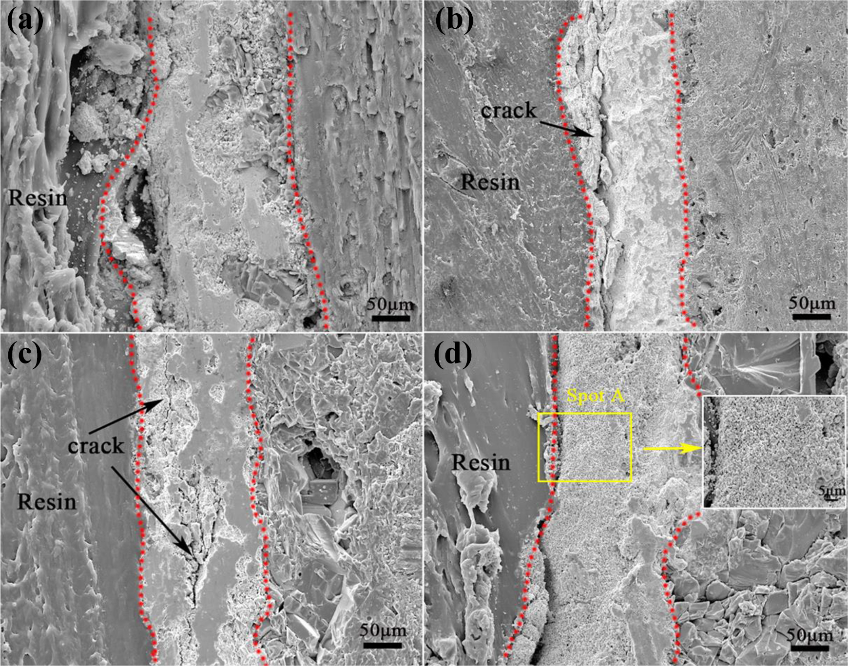
Figure 11 displays the cross-sectional backscatter micrograph of the HfC-SiC coating in the ablation transition region after ablation for different time. According to the Figure 11(a), it can be seen that the coating kept intact without crack and desquamation after ablation for 30 s. With the ablation going on, the micromorphology of the cross section in the ablation transition region was affected by the variation of the ablation center region. After ablation for 60 s and 90 s, as shown in Figure 11(b) and (c), some cracks were formed in the cross section of the ablation transition region, which was resulted from the propagation of the cracks generated in the ablation center region. And the cracks became more and more obvious with the increase of ablation time. After ablation for 120 s, due to the propagation of the cracks in the ablation center region and the mismatch of the CTE between outer and inner coating, a penetrating crack was finally generated in the cross section of the ablation transition region, which could be observed in Figure 11(d). Furthermore, there was a trend of crack propagation with the ablation continuing. In conclusion, because of the low temperature and parallel airflow, the oxidation of the HfC-SiC coating was restricted, and the structure of the coating in the ablation transition region was not destroyed obviously compared to that in the ablation center region.

Cross-sectional backscatter micrographs of the ablation transition region of the HfC-SiC coatings after ablation for different time: (a) 30 s, (b) 60 s, (c) 90 s, and (d) 120 s.
Conclusions
The sprayed HfC-SiC coating was mainly composed of different carbides and oxides. The Hf and Si elements distributed uniformly in the coating. The as-prepared coating was dense with little pinholes and crack free, and had a good bonding with the internal SiC coating.
The HfC-SiC showed good ability of ablation resistance. After ablation for 120 s, the linear and mass ablation rates of the HfC-SiC coating were −0.12 µm/s and 0.12 mg/s, respectively. During ablation, the evaporation of the oxidation products SiO2 could reduce the surface temperature of the coating, but also caused the formation of more pores on the surface coating. With the increase of ablation time, a dense oxide film was generated on the coating surface. Nevertheless, due to the phase transition of HfO2 and cooling contraction of the coating, some microcracks were formed on the surface of the coating in the ablation center region.
At the initial stage of ablation, the HfC-SiC could keep intact due to the low temperature and low oxidization degree. With the ablation going on, the oxygen diffused inward and brought about the oxidization of the inner coating, resulting in the formation of cracks in the cross section. After ablation for 120 s, part of the cross section of the coating was completely oxidized and formed a loose and porous layer in the ablation center region. Compared to the ablation center region, the temperature and pressure were low in the ablation transition region, thus the oxidization and sintering was slowed down.
Footnotes
Declaration of conflicting interests
The author(s) declared no potential conflicts of interest with respect to the research, authorship, and/or publication of this article.
Funding
The author(s) disclosed receipt of the following financial support for the research, authorship, and/or publication of this article: This work has been supported by the National Natural Science Foundation of China under grant no. 51472202 and supported by the Fund for Shanxi Key Subjects Construction (FSKSC).