
Abstract
Cylindrical gas film sealing technology is a new type of dry gas sealing technology. Compared with the face gas film sealing technology, the cylindrical gas film seal presents a strong floating property, which can reduce the vibration and thermal deformation of the rotor system. In this article, the effect of operating parameters such as speed, pressure difference and viscosity on the T-groove gas cylindrical film seal performance are studied in detail by the method of control variable in computational fluid dynamics software, and pressure distribution, gas film stiffness, leakage, leakage stiffness ratio and hydrodynamic force are analysed. Results show that with the increase of the rotational speed, static pressure, hydrodynamic force and film stiffness increase, but leakage decreases first and then increases. Furthermore, the results indicate that with the increase of pressure difference, the static pressure, leakage and hydrodynamic force increase. In addition, the simulations show that when the viscosity increases, the maximum pressure and film stiffness increase, but the leakage decreases. This indicates that as the rotational speed increases, the hydrodynamic effect and the amount of gas overflow in the axial direction increase, resulting in an increase of leakage. Lastly, the results also show that when the pressure difference increases, both the radial and axial gas flow rates increase, resulting in an increase in both the film stiffness and the leakage. With the increase of viscosity, the viscous shear force and fluid hydrodynamic force increase, resulting in the increase of the gas film stiffness. This study can provide a theoretical basis in industrial applications for setting the operating parameters and serving as a reference.
Keywords
Introduction
With the advancements in sealing technology, gas film sealing is emerging as an important new rotary shaft seal technology in aviation engines and industrial gas turbines. 1 Compared with other seal methods, gas film seal technology has lower leakage, lower wear, longer life expectation, lower energy consumption and simpler and more reliable operation. 2
Cylindrical gas film seal with large flexible support structure and floating sealing component are characterized by their high efficiency and low cost. Therefore, the fluid dynamic sealing technology is studied to apply it to high-speed fluid machinery such as aero engines, which has received much attention. 3
Ma et al. have done extensive research in cylindrical gas seal and studied the design of spiral groove structure, dynamic characteristics analysis and interface structure. Their results show that the cylindrical gas film seal is more suitable for the key parts of high-speed equipment such as aero engines. 4 –9 Liu et al. studied the static mechanical properties of cylindrical gas film seals and the sealing performance of the cylindrical gas film with a flexible support structure. They also studied the fluid velocity and gas shear stress in the flow field of different groove structures and found out the key factors affecting the dynamic pressure effect of the fluid. 10 –12 Zhao and Li optimized the cylindrical gas film seal rotor with different structural parameters, obtained the structural parameters corresponding to extreme values, and verified the calculation results, which proved the reliability of the optimized design. 13
A review of the literature reveals that most of the research on cylindrical gas film seals are mainly on the structural parameters and dynamic characteristics of the spiral grooves. The research on T-groove also mainly focuses on static properties and groove structure parameters. Compared with the spiral groove, the T-groove cylindrical gas film seal has the characteristics of two-way start, and it has better stability than the spiral groove during the starting and stopping phases. In this article, the T-groove cylindrical gas seal is taken as the research objective, and the corresponding model is established. The multilayer meshing technique is used, and the influences of the rotational speed, pressure difference and viscosity on the sealing performance of T-groove cylindrical gas seal are studied by control variable method. The results of this study can provide a theoretical basis for setting the operating parameters and serve as a reference for industrial applications.
Parameter definitions
The expansion diagram of T-groove cylinder gas film seal is shown in Figure 1. The parameter type and the corresponding values are provided in Tables 1 and 2.

The expansion diagram of T-groove cylindrical gas film seal.
Seal gas properties.

Parameters definition.
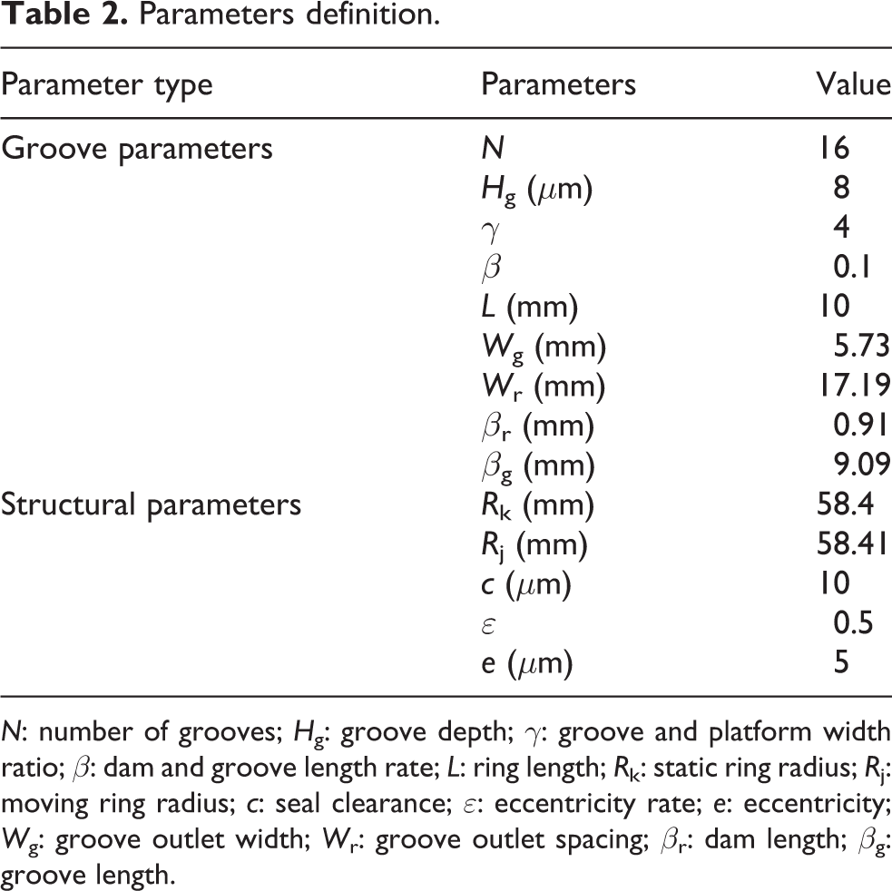
N: number of grooves; H g: groove depth; γ: groove and platform width ratio; β: dam and groove length rate; L: ring length; R k: static ring radius; R j: moving ring radius; c: seal clearance; ε: eccentricity rate; e: eccentricity; W g: groove outlet width; W r: groove outlet spacing; β r: dam length; β g: groove length.
Modelling and meshing
Parametric modelling
Firstly, the moving ring and static ring of the T-groove cylindrical gas film seal are established. A T-groove is provided on the inner surface of the gas film sealing static ring, and the groove parameters are provided in Table 2; then the T-groove gas film model is established, as shown in Figure 2.

The model structure of T-groove gas film.
Meshing
In this article, HYPERMESH and ANSA are used to build the meshes. The size between the overall structure of the cylindrical gas film and the gas film thickness is different. The maximum dimension of the model is tens of millimetres, and the minimum dimension is only tens of microns. So, a finer mesh should be divided along the thickness of the gas film. It is impossible to use the periodic analysis method like the face film seal because of the eccentric structure of the cylindrical gas film seal. Therefore, the entire model must be analysed. If the grid is divided by a simple method, the mesh might not meet the requirements of FLUENT calculation, and the simulation results are not accurate. Using HYPERMESH and ANSA, the model is cut and divided into groove and platform. The method of meshing from the surface to the body is used to control the mesh quality of the model, and the mesh is divided into hexahedral mesh structure. When the model is established, the boundary condition is easily set up. Figure 3 shows the entire meshing and local meshing.

Mesh structure of T-groove model: (a) macro grid and (b) local grid.
Model assumptions
Several assumptions are used here. Firstly, the fluid film between the moving ring and the static ring gap is a continuum medium and is in accordance with the Newtonian viscosity law. Secondly, there is no relative sliding between the gas film and the moving ring’s surface as well as the film and the static ring’s surface. Thirdly, the film is stable with no disturbance and vibration, and the moving and static rings in the process of operation do not suffer pressure deformation and thermal deformation. Lastly, the inertia and volume forces of the gas film are ignored.
Boundary conditions
Set the import boundary as a pressure entry, and set the exit boundary as a pressure exit, P s = 0.10 MPa. The moving ring wall is set to wall motion, and the designated z axis is the rotation axis of the moving ring. The static ring wall is set as a stationary wall boundary condition.
Solution set
FLUENT computational solver settings include numerical format, separation solver, discrete method and coupled solver. The finite volume method with SIMPLE pressure correction method is used and flux using first-order upwind style is calculated. The relaxation factor is set to the default value. If the residual curve develops upward, the calculation is interrupted, and the relaxation factor is adjusted to continue the calculation. Generally, it is not necessary to modify the default setting, because these default values are optimized according to the characteristics of various algorithms 14
Effect of operating parameters on sealing performance
Influence of rotational speed on sealing performance
Figure 4 shows the static pressure distribution at the root of the T-groove (Z = 2 mm), and the rotational speed at 6000, 8000 and 10,000 r/min. The position of Z = 2 mm is selected, because this position is the pressure outlet of the T-groove, and the parameter value at this position can accurately reflect the performance of the gas film seal. It can be seen from the figure that the static pressure in the middle area (X = −0.03 to 0.03) is obviously larger than the two-side area (X = −0.06 to −0.03 and −0.03 to 0.06). The reason for this is because the thickness of the gas film in the middle position is the smallest, resulting in strong wedging and fluid dynamic pressure effects and high pressure. The static pressure increases with the increase in the rotational speed; the rotational speed has great influence in the middle area, and the static pressure value of different rotational speed changes greatly, while the different rotational speed in the two-side area has little effect on the static pressure at different speeds. This indicates that when the film thickness is too large, the change in the rotational speed has little effect on the pressure.

Scatter diagram of static pressure distribution along axis of Z = 2 mm at different speeds.
Figure 5 shows the influence of rotational speed on hydrodynamic force and leakage. When analysing the effect of the rotational speed on sealing performance, the boundary pressure is determined to be 0.01 MPa, and the viscosity is 1.79 × 10⁻⁵ Pa s. The rotational speed ranges from 2000 r/min to 18,000 r/min, since this range includes the sealing performance of low-speed operation and high-speed operation. Figure 5 shows that the leakage is a convex curve with the increase of rotational speed. The leakage decreases initially with increasing rotational speed and then increases. When the rotational speed is 10,000 r/min, the leakage reaches the minimum value. With the increase of rotational speed, the hydrodynamic force increases, and the gas film stiffness increases in the rotational speed range.

Variation of hydrodynamic force and leakage with rotational speed.
According to the analysis, when the rotational speed is running from 2000 r/min to 10,000 r/min, the fluid dynamic pressure effect gradually increases with the increase of the rotational speed, and the overflow of the gas along the axial direction is well sealed, so the leakage amount is reduced. However, when the rotational speed exceeds 10,000 r/min, the centrifugal action gradually increases due to the movement of the gas following the moving ring, so the gas overflow in the axial direction increases, and the leakage amount gradually increases with the rotational speed. This indicates that under certain working conditions, when the rotational speed changes, the leakage has a minimum value, and the corresponding rotational speed is optimal. In this example, the optimal speed is 10,000 r/min.
Figure 6 is the curve of the variation of the maximum pressure and frictional torque with the rotational speed. It illustrates that as the speed increases, both the maximum pressure and the frictional torque increase. This also indicates that there is a linear correlation between the rotational speed and the maximum pressure. However, the growth rate of maximum pressure is obviously larger than the frictional torque’s growth rate.

Variation of maximal pressure and frictional torque with rotate speed.
Effect of pressure difference on sealing performance
Figure 7 shows the distribution of static pressure in the circumferential direction at Z = 2 mm with the pressure difference 0.01, 0.04 and 0.07 MPa. It shows that the static pressure in the middle area (X = −0.03 to 0.03) is obviously larger than the two-side area (X = −0.06 to −0.03 and 0.03 to 0.06). In the middle area, because the thickness of film is very thin, and the booster effect is strong, the static pressure is very high. The static pressure increases with the increase in the pressure difference. When the pressure difference increases, the values of static pressure on the entire circumference are changed. Compared with the influence of rotational speed on static pressure, the pressure difference has obvious influence on the static pressure value on the entire circumference. This indicates that the pressure difference has a strong effect on the static pressure on different film thicknesses.

Scatter diagram of static pressure distribution along the axis of Z = 2 mm at different pressure difference.
Figure 8 shows the effect of pressure difference on the hydrodynamic force and the leakage. The rotational speed and the viscosity are fixed at 8000 r/min and 1.79 × 10⁻⁵ Pa s, respectively, and the pressure difference ranges from 0.01 MPa to 0.09 MPa. The results show that as the pressure difference increases, both the leakage and the hydrodynamic force increase. When the pressure difference is <0.02 MPa, the change is not obvious. But when the pressure difference is >0.02 MPa, the pressure difference plays a leading role in the leakage, and the leakage increases linearly with the increase of the pressure difference. In the large pressure difference environment, the hydrodynamic force is also increasing, which shows that the increase of the boundary pressure difference has influence on the hydrodynamic force. The large pressure difference indicates that the gas pressure pumped into the film sealing system becomes larger, which leads to increase in the fluid dynamic pressure gas flowing out from the flow field and, therefore, leakage.
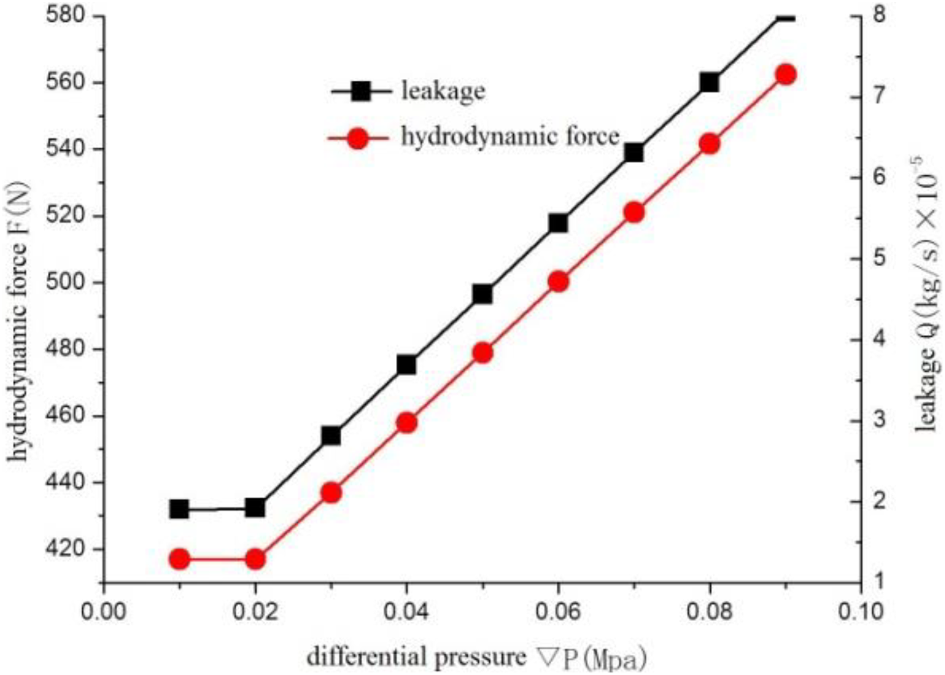
Variation of hydrodynamic force and leakage with pressure difference.
Figure 9 shows the effect of pressure difference on maximum pressure and frictional torque. The results in this figure illustrate that the boundary pressure difference has a great influence on the maximum pressure and frictional torque of the T-groove cylindrical gas film seal, and the effect of pressure difference on frictional torque is stronger than that on maximum pressure. This indicates that when the rotational speed is constant, the frictional torque increases as the pressure difference increases, and the cylindrical frictional power consumption also increases. Furthermore, power consumption has a linear relationship with pressure difference.

Variation of maximal pressure and frictional torque with pressure difference.
Effect of medium viscosity on sealing performance
Figure 10 shows the distribution of static pressure in the circumferential direction at Z = 2 mm, and the viscosity at 0.5 × 10⁻⁵, 1 × 10⁻⁵ and 1.5 × 10⁻⁵ Pa s. It can be seen from the figure that the static pressure in the middle area (X = −0.03 to 0.03) is larger than that in the two-side area (X = −0.06 to −0.03 and 0.03 to 0.06), and the pressure value increases when the viscosity increases. In the middle area, the effect of viscosity on the static pressure is significant. However, in the two-side area, viscosity has little effect on the static pressure. This indicates that the viscosity has different effects on the static pressure at different film thicknesses, and the smaller the film thickness, the greater the effect of viscosity on the static pressure.

Scatter diagram of static pressure distribution along the axis of Z = 2 mm at different viscosity.
Figure 11 shows the effect of viscosity on the leakage and hydrodynamic force. Under certain conditions, when the viscosity increases, the leakage decreased significantly. However, when the viscosity is greater than 1 × 10⁻⁵ Pa s, the rate of decrease of the leakage slows down. That is because when the viscosity increases to a certain value, the viscous shearing force generated by the gas which is moved by the moving ring is gradually increased, and the increased viscous shear force reduces the outflow of the gas in the axial direction, so the leakage is reduced. The hydrodynamic force, however, decreases with the increase of viscosity. This indicates that when viscosity increases, gas power consumption increases, but gas flow velocity in the flow field, hydrodynamic effect and hydrodynamic force decrease.

Variation of hydrodynamic force and leakage with viscosity.
Figure 12 shows the effect of viscosity on frictional torque and maximum pressure. When viscosity increases, maximum pressure increases linearly, but the frictional torque does not change with viscosity. This indicates that increasing the viscosity increases the retarding effect of the gas at the boundary position and therefore increases the local pressure, which is the reason why the maximum pressure appears at the bottom of the T-groove. When the friction area is constant, the frictional torque between the fluid layers is proportional to the velocity gradient and viscosity. With the increase in viscosity, the fluid velocity decreases significantly, and the velocity gradient between the layers decreases. Therefore, under the combined action, the change of the frictional torque is not significant.
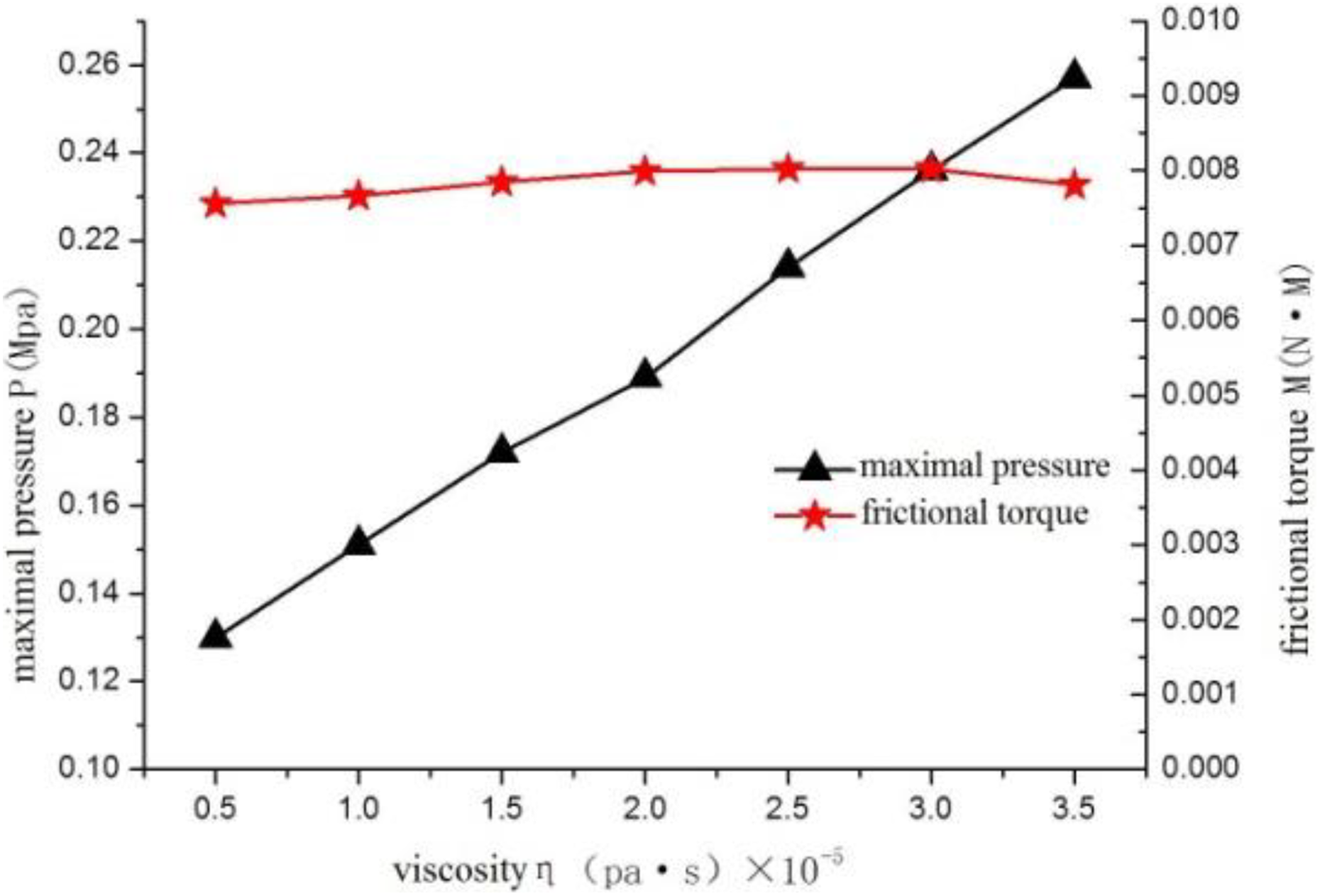
Variation of maximal pressure and frictional torque with viscosity.
Summary
With the increase of rotational speed, the pressure-raising effect of gas film is enhanced, the static pressure increases, the hydrodynamic force increases linearly, and the film stiffness also increases accordingly. The leakage begins to decrease and then increase with the increase of rotational speed, and hence there exists a minimum value. This indicates that with the average film thickness being constant, as the rotational speed increases, the outflow of the gas in the axial direction first decreases and then increases, so the rotational speed has a critical value. Under the experimental conditions of this article, the optimal rotational speed is 10,000 r/min.
When the pressure difference increases gradually, the static pressure of gas film increases in the whole circumferential direction, and the leakage and hydrodynamic force increase. These results show that the larger the boundary pressure difference, the larger the film stiffness, but it also brings a relatively large leakage. This indicates that the greater the inlet pressure, the greater the gas velocity in both the radial and axial directions, resulting in an increase in gas film stiffness and an increase in gas leakage.
With the increase of viscosity, the viscous shearing force increases, the leakage decreases, the maximum pressure increases linearly, and the film stiffness also increases accordingly. This indicates that when viscosity increases, the gas viscous shear force increases, the gas outflow in the axial direction decreases, the leakage decreases, and with the viscosity increases, the gas power consumption increases, the gas flow velocity in the flow field decreases, the hydrodynamic effect decreases, and the hydrodynamic force decreases.
Footnotes
Declaration of conflicting interests
The author(s) declared no potential conflicts of interest with respect to the research, authorship, and/or publication of this article.
Funding
The author(s) disclosed receipt of the following financial support for the research, authorship, and/or publication of this article. This work was supported by the National Natural Science Foundation of China (grant no. 51765024) and the Yunnan Science and Technology Plan Project (grant no. 2017FD132). We gratefully acknowledge the relevant organizations.