
Abstract
The determination of mechanical properties at the nanoscale is of such importance today that researchers pay special attention to it. Discovering the mechanical properties of biological composite structures in the nanoscale is much interesting today. Top neck mollusk shells are among biomaterial nanocomposites that their layered structures are composed of organic and inorganic materials. Since the nanoindentation process is known as an efficient method to determine mechanical properties like elastic modulus and hardness in small scale, therefore, due to some limitations of considering all peripheral parameters, particular simulations of temperature effect in the atomic scale are considerable. The present article provides a molecular dynamics approach for modeling the nanoindentation mechanism with three types of pyramidal, cubic, and spherical indenters at different temperatures of 173, 273, 300, and 373°K. Based on load-indentation depth diagrams and Oliver–Pharr equations, research findings indicate that the temperature has weakened the power between the biological atoms; this leads to reduced mechanical properties. An increase in temperature causes a reduction in elastic modulus and hardness. There was correspondence between the results obtained from the spherical indenter and experimental data. This study can be regarded as a novel benchmark study for further research studies which tend to consider structural responses of the various bio-inspired nanocomposites.
Introduction
New findings in the technology and science cause more than ever attention of scientists toward biomaterials and nanoscience. Biological creatures are among the materials in the nature that have various types of structures in the nanoscale and microscale. The structure of most biomaterials in the small scale is a multilayer nanocomposite that causes marvelous mechanical and physical properties. 1 –3 Mollusks are multilayer nanocomposites with irregular and intricate structure, although this complicated structure is a simpler structure compared to other biological structures. 4,5 Mollusks have diverse types and species that are classified into seven groups of: (1) column structure, (2) planar structure, (3) horny structure, (4) prismatic structure, (5) layered structure, (6) multiplex layered structure, and (7) homogeneous structure 6 (Figure 1).
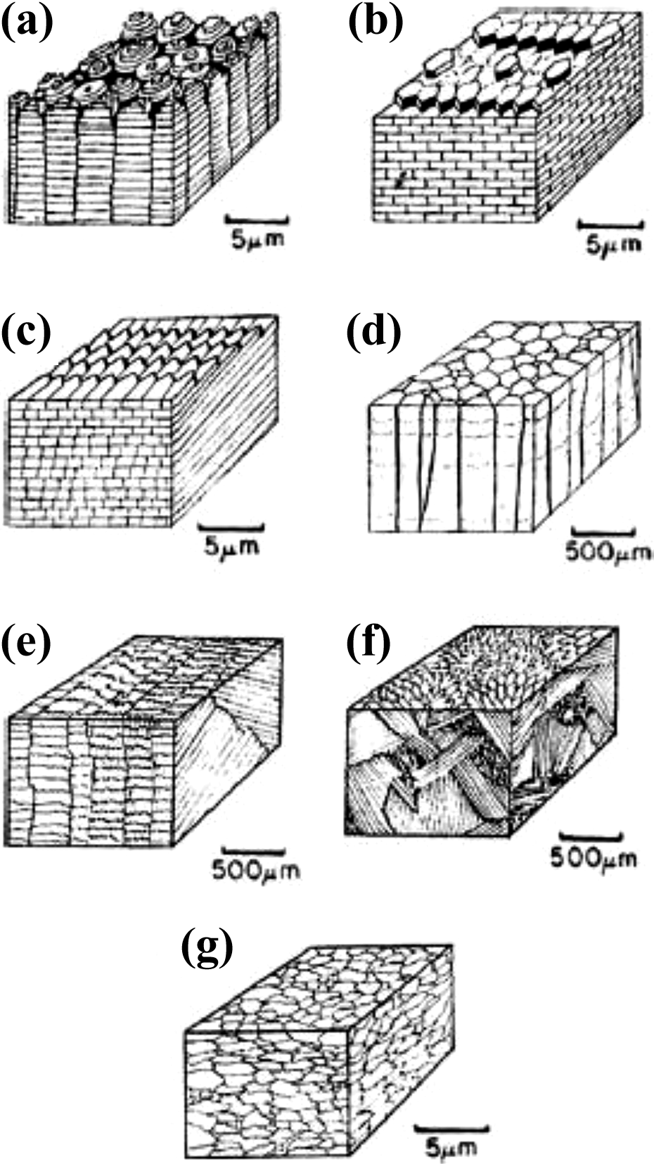
The structures forming sea shells. (a) Column structure. (b) Planar structure. (c) Horny structure. (d) Prismatic structure. (e) Layered structure. (f) Multiplex layered structure. (g) Homogeneous structure.
The forming structure of mollusks is a combination of organic and inorganic materials, which inorganic materials are organized in the organic substrate. 7,8 Ductility is one of the mechanical properties that is inversely related to the strength of materials, but because of the special structure of biomaterials, these two factors are found together in the biomaterials so that in case of external forces, they can both show flexibility and strength to confront it. This is an exclusive feature of biomaterials. Mollusks are among sea biomaterials that are no exception to this feature and are one of the biomaterials that their crust function is basically mechanical and provides protection of the biomaterial inside the shell and acts like a shield. The reason for this unique feature of biomaterial engineering structure including mollusks is that biological creatures can produce compounds in which organic and inorganic components lie together or are combined together in their complicated structure for their survival. 9 –11 The mollusk shell is an irregular nanocomposite structure composed of inorganic (aragonite) and organic (chitin + glycine) materials together in hierarchical layers 12 (Figure 2).

SEM-FE images of top neck mollusk shells in different scales. SEM-FE: scanning electron microscope–field emission.
The main constituent of this structure is aragonite, which forms the maximum weight percentage of the biomaterial. 13 Together with organic materials, it forms nanolayered composite. 14 This issue caused the researchers to study the mechanical properties of this biomaterial and they are inspired by this for the structure of engineering materials 15 (Figure 3).
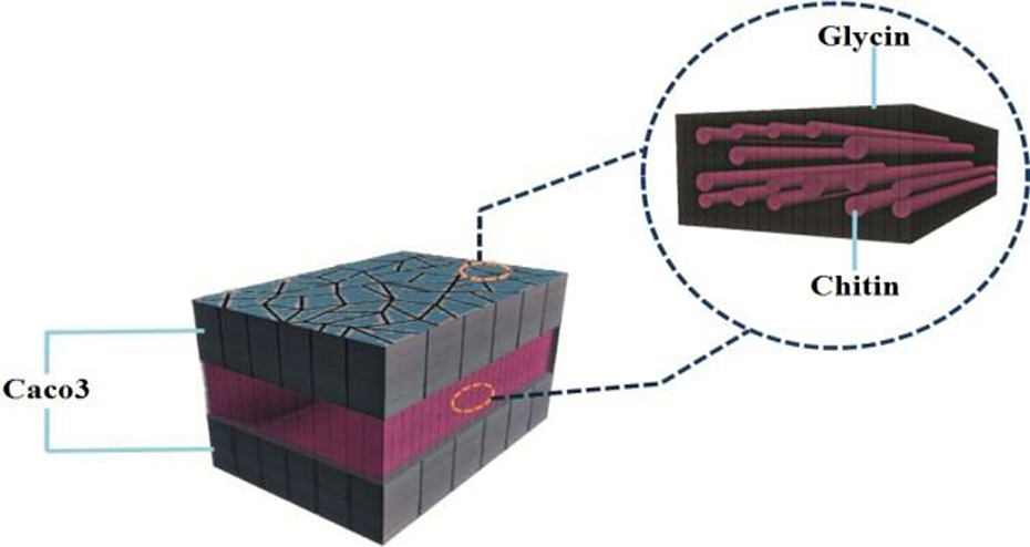
Hierarchical structure of mollusk.
There have been many studies on engineering and biomaterials to determine their mechanical characterization investigating microstructure properties using experimental nanoindentation methods. 3,12,14,16 –22 It is obvious that most of them carried out in past decade are concerning about microstructure and mechanical properties of two types of mollusks: conch and abalone.
So, the main focus of this article is on the mechanical characterization of another type of mollusks, that is, top neck mollusk shells. Due to nondestructive nature of the nanoindentation, the method is known as a popular method and is widely used. But, in spite of the great advantages, the method has some limitations too. Therefore, due to significant sensitivity of indenter tip and experimental test apparatus, the effects of some parameters such as temperature, humidity, and so on. On the mechanical properties of the sample could not be performed. Therefore, nowadays, the numerical methods are used in the atomic scale to investigate the effect of these parameters. 7,21 Today, development of molecular dynamics (MD) simulations in various engineering sciences has become popular. Among the works developed for the nanoindentation mechanism, although, some reports have been introduced by Patodia et al., 23 Kizler and Schmauder, 24 Peng et al., 25 Ciccotti, 26 Rocha et al., 27 Fang and Wu, 28 and Peng and Zeng. 29 But there are no studies on the biomaterials including mollusks. Of courses, we can mention some studies of Zhang et al., 21 Patodia et al., 23 Yu and Lau, 30 and Jin et al. 31 were done on the basis of the organic protein materials as the same of our work.
Accordingly, simulations of MD method have various capabilities and yet there has been no availability, the atomic scale effort to characterizing the hardness and elastic modulus of the top neck mollusk shells. Here, authors intend to investigate the problem by means of two different methods; the MD simulations and experimental considerations of the nanoindentation process.
Nanoindentation testing
Materials
All biological samples were oysters collected from the Persian Gulf, as shown in Figure 4.

(a) The interior view of oysters (b) The exterior view of oysters.
Sample preparation
To reduce the error in the tests, the preparation method of the top neck mollusk shells for different conditions was equal. First, the shell was prepared, then a section with the dimensions of 1.0 × 5.0 × 1 mm were prepared using a diamond knife and then inserted in a mold filled with resin (1 cm in diameter), and then for the tightening, the samples were molded for 18 h at room temperature for the resin to be cured (Figure 5).

Sample preparation for nanoindentation test: (a) sample cutting and (b) fixed sample inside resin.
Then, the samples were polished with emery paper to make the surface completely polished. To avoid any scratches on the surface, the samples were polished with different emery papers and finally, the surface quality degree was controlled using an optical microscope. To ensure that there are no scratches on the sample surface, after completion of the preparation stage, the samples were delivered to the laboratory for nanoindentation tests.
Nanoindentation method
It has made it possible to analyze and determine mechanical properties like elastic modulus, hardness, creep behavior, and fracture toughness of materials. Piezoelectric-based Newtonian electromagnetic forces in the nanoscale and microscale are applied on the surface of the material and the diagram of applied force variation versus indentation depth (hereafter called “depth”) is measured. Elastic modulus and hardness are among typical mechanical properties measured during indentation process, and both of these parameters could be calculated as a function of depth. 32 Since nanoindentation test is considered as a nondestructive test, it is widely used by researchers and it is fairly popular. The indenter is the principal component of the indentation system, which has different geometries, shown in Figure 6. But, the most common type of the indenters is a Berkovich pyramidal indenter (Figure 6(d) and Table 1).
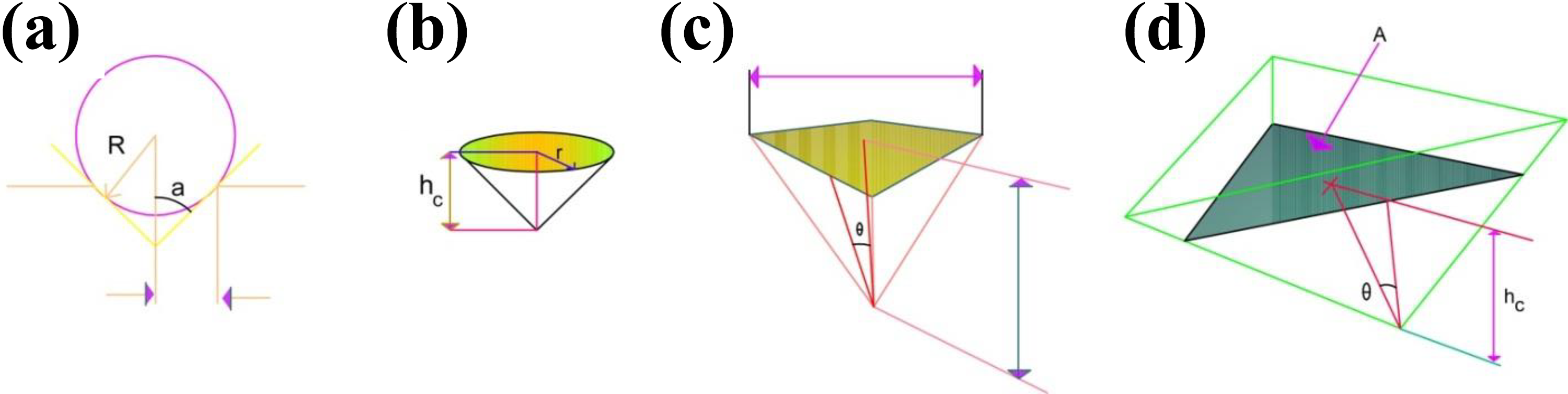
Different types of indenters: (a) spherical, (b) pyramidal, (c) conical, and (d) Berkovich.
The Berkovich nanoindenter properties. 33

The results of the indentation test are used to obtain the elastic modulus and load-indentation depth graphs (Figure 6). The test covers the recording of the force versus indentation depth during loading from zero to maximum indentation load and again from maximum load to the zero point.
Figure 7 shows the maximum values of load and indentation depth. Moreover, mechanical properties like elastic modulus and hardness are obtained by measuring the slope of the diagram in the loading area (S). Equation (1) is used to obtain the hardness.

Force-depth diagram in nanoindentation test.
F max and A are the sample’s hardness, maximum indentation load, and real contact area, respectively. Equation (2) is used to calculate A c, which is associated to the projection area in the distance from the indenter tip 32 (Figure 7).

This equation usually fits with experimental data with good consistency (in a wide range of contact depths, as far as empirical data are taken on the reference sample surface). For any indenter, C1, C2, and C3 are geometric parameters in Equation (2) are geometric parameters of the indenter tip 34 ; so this could be obtained as Table 2.
The relationship between the contact area and indentation depth for different indenters.

The h c is the elastic deflection of the surface at a particular contact perimeter and it depends on the indenter geometry, 32 therefore it could be obtained as:

h s is calculated by the following equation.

In this equation, ε is the indenter geometry contact and s is the curve slope of the load-indentation depth diagram under loading (Figure 7). 32 The real contact area is obtained using equations (2)–(4), hardness of the sample is also obtained by insertion of the data from Table 1 in equation (1). Finally, equation (5) is used to obtain the elastic modulus
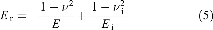
E s and E i are Young modulus of the sample and the indenter, respectively, ν s and ν i are the Poisson ratio for the sample and indenter, respectively. In a diamond probe indenter the elastic modulus (E r) decreases. As the indenter is not completely rigid, during the unloading some deformation occurs. It is therefore called the reduced elastic modulus and is calculated using the following equation:

where B is the geometric constant of the indenter’s tip, 32 whose values for the cubic and pyramidal indenter are 1034 and for spherical indenter 1. E s (elastic modulus of the sample) is obtained with the Poisson’s coefficient of the indenter (ν i), the elastic modulus of the indenter (E i), the Poisson’s coefficient of the sample (ν s), and the reduced elastic modulus (E r) using equation (6).
MD simulation
MD simulation is based on Newtonian second law. In Newtonian interpretation of dynamic, the transfer movement of a particle (molecule, atom, etc.) is caused by a force which is imposed by an external factor on it. In other words, Newtonian second law develops a direct relationship between movement and imposed force. This method is very popular due to its capability in the nanoindentation simulation atomic phase transformation. 7,35 MD simulation is a numerical method from Newtonian movement equations for a set of atoms. 27,35,36 In this article, the top neck mollusk shells nanocomposite was simulated using PACKMOl software. Nanoindentation process was coded in LAMMPS (2018 version). The visual molecular dynamics (VMD) and open visualization tools were used for visualization . So that, PACKMOL software is geometric building software so that PACKMOL creates an initial point for MD simulations by packing molecules in defined regions of space. The packing guarantees that short range repulsive interactions do not disrupt the simulations. Output data from the PACKMOL software can be used as input files for performing the nanoindentation process in MD software such as the LAMMPS and also VMD is a molecular modeling and visualization computer program. VMD is developed as mainly a tool to view and analyze the results of MD simulations. In this simulation, the indenters were diamonds that were applied on the surface of the bio-nanocomposites. The atoms used for the construction of used indenters (Figure 8), were carbon with atomic number of 12 that the number of its atoms for construction of the indenters with different geometries and their complete information is shown in Table 3.

Different indenters’ simulation: (a) spherical indenter, (b) pyramidal indenter, and (c) cubic indenter.
The simulated indenters’ specifications.

The samples in this simulation process are a bio-nanocomposite that its dimensions in the X, Y, and Z directions are 160, 180, and 160 Å, respectively (Figure 9).
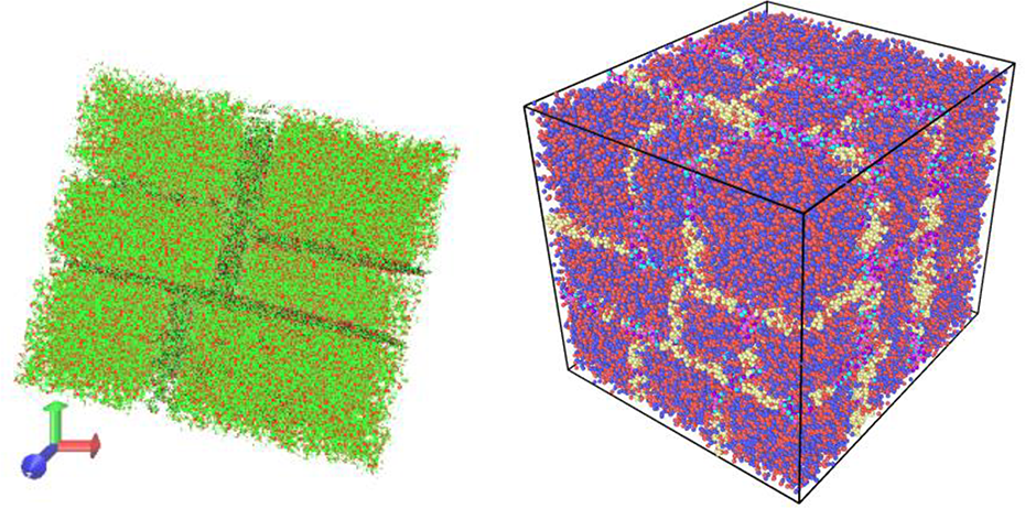
Molecular dynamics simulation of the bio nanocomposite.
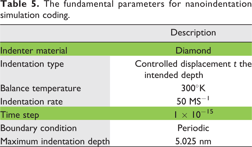
As it is shown in Figure 9, the bio-nanocomposite has an irregular structure and organic materials (chitin–glycine) are between aragonite blocks. In this simulated structure, there are 3,14,502 atoms used that from these numbers, aragonite has 1,91,802 atoms and glycine has 44,135 atoms, and chitin has 78,565 atoms. All the atoms used in this structure are five types of H, C, N, Ca, and O. The temperatures used in this process are 173, 273, 300, and 373°K and the movement equations are integrated using Verlet algorithm 37 with time steps of 1 × 10–15 s. The variables in the nanoindentation process are listed in Table 4, and the main parameters for process coding are shown in Table 5. In this process, boundary condition is fixed at the bottom surface of the sample.
The MD simulation parameters.

MD: molecular dynamics.
The fundamental parameters for nanoindentation simulation coding.
According to this, to start the nanoindentation processes, at first, the indenters are in contact with the top neck mollusk shells nanocomposite (Figure 10).

Nanoindentation process simulation on the top neck mollusk shells with different indenters. (a) Cubic indenter. (b) Pyramidal indenter. (c) Spherical indenter.
The next step is the selection of a force field for consideration of interactions between atoms in MD simulation and it is an important step to express the potential function.
So that for a molecular system with N particles the following equation will be obtained:

In this equation, r is the atom center location vector, Q
1 represents the external field effect, Q
2 is the interaction of molecular pair, and Q
3 is the interaction between the three particles. In this article, Dreiding potential function was used to calculate the mutual forces between H, C, N, Ca, and O atoms. This potential function has four principal terms as follows: bond stretching term; changes in bond angle term; changes in dihedral rotation term; and van der Waals non-bonded interactions term.
According to this, the general form of Dreiding potential function is as follows:

In equation (8), the terms E bond (r), E angle (r), E dihedral (r), and E non-bonding (r) are calculated via equations (9)–(11) and (13).


where θe and re are the equilibrium bond angle and bond length, kθ and kb are stiffness constants for the bond angle potentials and bond length potentials, respectively. On the other hand, the kb in each band is 700 kcal mol−1/A−2 and depending on the number of the atoms that form the angle and based on the number of the angles, the value of Kij (n) = nKij (1) will be obtained so that for n = 1, n = 2, and n = 3 the value of kθ will be obtained as 700, 1400, and 2100 kcal mol−1/A−2 and Ci represents the coefficients of dihedral multi-harmonic. The Ci value is calculated with the following equation that is dependent on the effect of indenter rupture on the atoms. The value of Ci is calculated from the following equation, which depends on the effect of the collapse failure on the atoms.

where the value of Cij
is obtained by having the value Kij
and
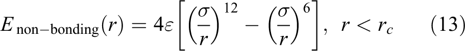
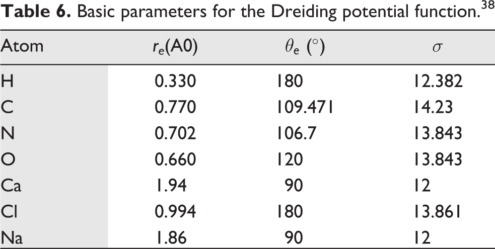
where r is the distance between two atoms, σ is the distance at zero energy, ε is the energy well depth, and rc is the cut-off distances that is taken as 10.5 Å. These training sets were selected based on minimized energy of the nanocomposite structure. Basic parameters applied for the Dreiding potential function selected by “Dreiding: a generic force field for molecular simulations.” Such that using these parameters, rational solutions were obtained. In particular for this study, the value of each constant for top neck mollusk shells nanocomposite is presented in Table 6.
Basic parameters for the Dreiding potential function. 38
Also, in this process, for balancing the system, an NVT thermostat and following a NVE thermostat for temperature control in various temperatures are used.
Results and discussion
In the loading and unloading time, indenter penetrates in the sample and causes the destruction of the sample. As shown in Figure 11, the indentation extent for different indenters in various times is different.
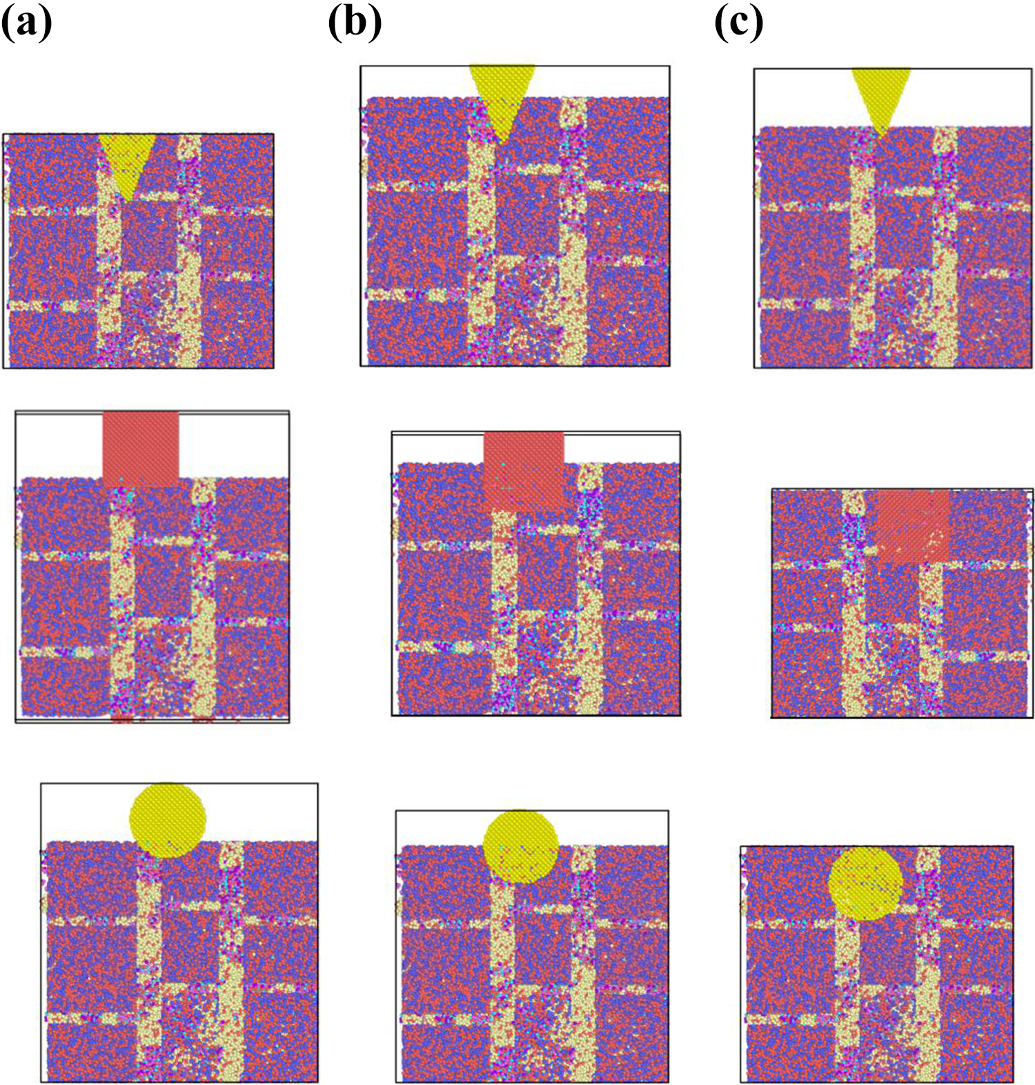
The indentation of different indenters in different times. (a) Pyramidal indenter. (b) Cubic indenter. (c) Spherical indenter.
The output of the loading and unloading of the indentation process is load-indentation depth. Figure 12 shows the load-indentation depth diagram resulted from nanoindentation process using spherical, cubic, and pyramidal indenters on the top neck mollusk shells nanocomposite in the temperatures of 173, 273, 300, and 373°K for various indenters.

Force-indentation depth diagram of MD simulation. (a) Pyramidal indenter. (b) Cube indenter. (c) Spherical indenter.
As shown in Figure 12, in the equal maximum indentation depth, the required force to reach this displacement for various types of indenters in different temperatures are different. With information like maximum load, indentation depth, and information about the sample and indenter, the elastic modulus can be obtained, which for this the slope of the diagram during unloading must be calculated. The needed information like h max, f max, S, ν, νi , Ei , and E are shown in Table 7.
Effective parameters for calculating the mechanical properties in MD simulation.
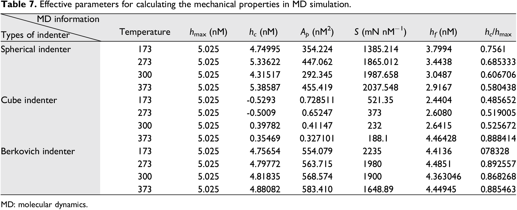
MD: molecular dynamics.
Using the data in Table 7 and equations (1) –(6) the elastic modulus of the top neck mollusk shells nanocomposite will be determined with other outputs of the MD simulation shown in Table 8.
Elastic modulus obtained using various indenters.

In the following, the results of the nanoindentation test for comparison with the obtained results were analyzed. In this way, after sample preparation, for the nanoindentation test, the diamond indenter (Berkovich type) with loading and unloading rate of 20 mN min−1 and the load of 10 mN is applied on the sample surface. Nanoindentation on the sample, as shown in Figure 13, was applied on five points that for every indent, there would be an indentation effect and a load-indentation depth will be obtained.

Effect of indenter on the sample.
Therefore, to analyze this process, five different graphs of load versus indentation depth like Figure 14 must be plotted.

Force-indentation depth diagram of top neck mollusk shells.
Loading and unloading type in the experimental test linearly increased from 0 to 100 µN, and then in the unloading, the load decreased from 100 µN to 0 (Figure 15). The extracted parameters from Figure 14 are shown in Table 9.
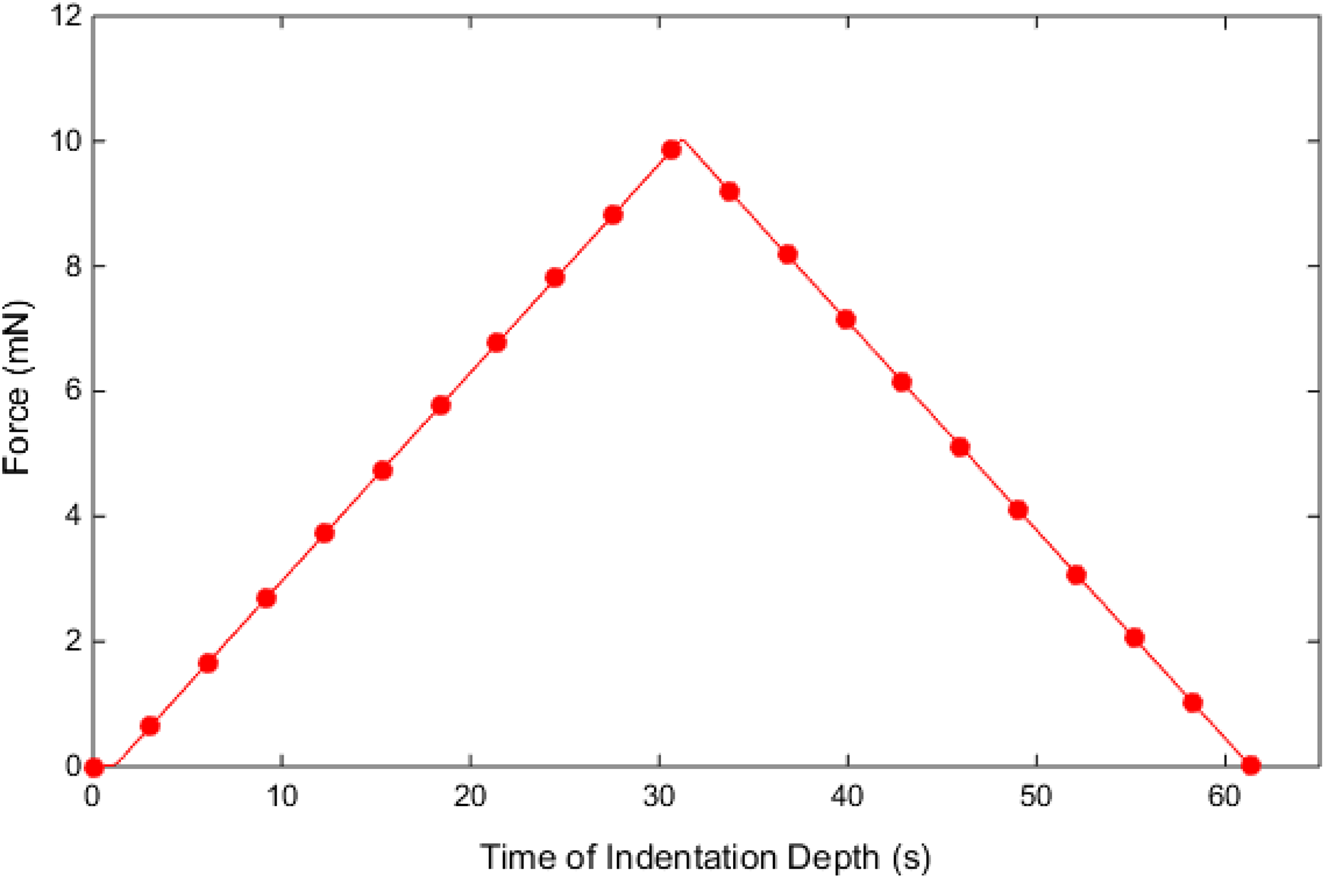
Force–time diagram at loading and unloading stage.
Effective parameters in calculation of mechanical properties.

To calculate the mechanical properties of each sample like elastic modulus and hardness, in general, the mean elastic modulus and the obtained hardness should be calculated and these calculated parameters should be considered as the mechanical properties of the samples. Finally, using the data in Table 9 and equations (1) –(6), the elastic modulus (Figure 16) and hardness (Figure 17) will be calculated.

Total elastic modulus of top neck mollusk shells sample with MD.

Total hardness of top neck mollusk shells sample with MD.
According to this, the elastic modulus and hardness of top neck mollusk shells using experimental nanoindentation method will be calculated as 4625.749 and 84.110 GPa. To validate the experimental tests and MD, it is necessary to justify some deficiencies in the MD simulation. One of the deficiencies in the MD process is that the time and calculation source has made the conditions difficult for validation of MD simulation with experimental tests so that it has confided the longitudinal scales to some nanometer or thousands or millions of atoms. Moreover, the rate used in MD simulation versus the experimental rate is a factor that may cause unreal or unwanted effects on the output results. Therefore, it might be predicted that the rate change in the nanoindentation process can make strain rate variation. In this article, to study the effect of loading, some experiments using MD at various rates of 10, 50, 100, and 150 m s−1 were carried out.
As it is deduced from Figure 18, the loading rate does not have much effect on the load-indentation depth diagram, which these results are consistent with Niihara 39 obervations, that he claimed that large hydrostatic parts effect (penetration in nanoindentation process) can cause plastic deformation in any material. Nevertheless, Tables 8 and 10 demonstrate comparing mechanical properties of top neck mollusk shells obtained from two different methods of MD simulation and experimental test method.

Load-indentation depth diagram at various rates. (a) Cubic. (b) Pyramidal. (c) Spherical.
Mechanical propertied from experimental method and MD simulation.

MD: molecular dynamics.
As shown in Figure 19, when using spherical indenter in MD simulation, the elastic modulus and hardness will be 99,239 MPa, 6.4348, for pyramidal indenter, the elastic modulus and hardness will be 0.033 MPa and 0.92 GPa, for cubic indenter, the elastic modulus and hardness will be 1.21348 MPa and 4076.737 GPa and the results from experimental nanoindentation test presents the elastic modulus and hardness of 4635.749 MPa and 84.110 GPa.

Comparison of the mechanical properties obtained using two different indenters: (a) elastic modulus and (b) hardness.
Therefore, it is well understood that nanoindentation simulation using MD method gives helpful information about various types of indenters. However, as shown in Table 7 about the spherical indenter tip, it is not comparable with experimental tests. On the other hand, in the experimental nanoindentation test, because of the Berkovich indenter with some nanometer tip (not being sharp in the nanoscale), it could be considered as spherical indenter. The difference is that the indenter with sharp tip will cause shear stress in the sample, but the spherical indenter causes elastic stress in the sample. This is because that in the equal indentation depth, the energy needed for deformation of the top neck mollusk shells nanocomposite in spherical indenter is higher than pyramidal (conical) indenter.
Generally, it could be deduced that the results of the MD simulation using spherical and cubic indenters for determination of elastic modulus and hardness are in good consistency with the results obtained from experimental indentation using the Berkovich indenter, and there is good consistency between the MD simulation and experimental tests. A very important point, about the experimental and numerical diagrams is this. As shown in Figures 12 and 18, all force-indentation depth diagrams have peaks and high fluctuations for three indenters. It seems that these are irregular structures of top neck mollusk shell. As it has been explained, displacement control method has been used for simulating MD of nanoindentation process (displacement control). Based on this, different forces are obtained in different displacement. When an indenter collides with CaCO3, more force should be imposed due to the high strength of minerals and when indenter enters in organic material phase (Kitin–Glycin), it needs a much less force because of the high flexibility and low strength. On the other hand, since the contact area of indenter with nanocomposite is different in various depths (different moments), different forces obtain. This can explain the reason of high fluctuations and peaks.
As seen in Figure 14, there is no sudden variations because the controller used in the experimental method is force controller (force controller), that is, the force increases periodically from 0 mN to 10 mN, and then reaches from 10 mN to 0 mN. The depth of indentation is calculated in this interval. As the contact surface of indenter with sample increases in the lower depths, force-indentation depth diagram takes more regular form in the experimental for.
Conclusion
In the present article, mechanical properties like elastic modulus and hardness of the top neck mollusk shells nanocomposite had been done using MD simulation in different temperatures and indenter shapes. The mechanical properties were determined using load-indentation depth diagrams and Oliver–Pharr equations. To compare the mechanical properties of various indenters, the results of the MD in the temperature of 300°K were compared to experimental results. The results showed that the hardness obtained by cubic indenter was in good consistency with experiments as well as the elastic modulus obtained by means of spherical indenter. Accordingly, it can be concluded that as the temperature increases the elastic modulus and hardness of the sample decrease. This is consistent with previous work 40,41 that states with the increase of the temperature, the hardness, and elastic modulus decrease.
Footnotes
Declaration of conflicting interests
The author(s) declared no potential conflicts of interest with respect to the research, authorship, and/or publication of this article.
Funding
The author(s) received no financial support for the research, authorship, and/or publication of this article.