
Abstract
Fiber-reinforced polymer (FRP) composites are becoming suitable and substantial materials in repairing and replacing conventional metallic materials because of their high strength and stiffness. Steel beams can be strengthened in flexure using bonded FRP or using steel plates. In such plated beams, shear forces develop in the bonded beam and these will be transferred to the FRP plate via the adhesion technique. Thus, the interfacial shear stress and normal stress will develop consequently, and debonding may occur at the FRP plate ends due to high interfacial stress values in this area. This original research aims to study the debonding phenomenon using an analytical and a numerical finite element models, in order to identify the interfacial stresses of a steel beam strengthened by the FRP plate with taper model, taking into account a new coupled approach of prestressing force and hygrothermal effect. This article explores the effects of various parameters, such as geometrical and physical properties, on the stress behavior of FRP composites.
Introduction
Composite material made from two or more immiscible components together produce material with properties that exceed the individual components. Experts and researchers determined various solutions to deal with the crucial problem of structures aging caused by different loads (mechanical load, temperature, humidity, hygrothermal effect, corrosion, etc.), and they have been using new composite materials, fiber-reinforced polymers (FRPs), which have several practical applications. The FRP composites have been mainly used to reinforce concrete and steel beams; extensive research has shown that the bonding between an FRP plate to the face of concrete and the steel beam can effectively develop its capability force and ultimate strength; these types of reinforced models have been able to reduce the influence of the interfacial stresses effect, which are affected by the phenomenon of solicitations, and the success of this technique is due to the effect of the transferred interfacial stresses from the beam to the externally bonding FRP. Several works have been developed by Wu et al., 1 Roberts, 2 Saadatmanesh and Malek, 3 and Triantafillou and Antonopoulos 4 to study the debonding phenomenon, while they have omitted several parameters in their studies. Smith and Teng 5 presented an accurate and widely applicable solution, especially they have taken the flexural stiffness of the bonded beam and plate. Lau et al., 6 presented a simple theoretical model for estimating interfacial stresses, in which fiber orientations are considered in their analysis. However, this method does not take into account the effects of bending deformations in the plate and the thermal effect on the structures. In addition, an improved solution for calculating interfacial stresses in concrete beams reinforced with FRP plates is developed by Tounsi, 7 in which shear deformations are considered, but the FRP fiber orientations are ignored. The solution developed by Kerboua et al. 8 supports the shear deformation effects in their model under the thermal load using typical coefficients of thermal expansion. In some studies, the difference between the coefficients of thermal expansion is another important problem in steel beams reinforced with FRP plates. Denton 9 found that the interfacial stresses can be developed in the adhesive layer at the ends of the FRP composite as a result of the difference between the coefficients of thermal expansion. Deng et al. 10 presented a simple method for obtaining the interfacial shear and normal stress using a taper model in the composite plates under the thermal and mechanical loads, while Hart-Smith 11 proposed the use of lap joints to minimize stress concentrations. The use of the taper at the ends of the adherend has been shown to effectively limit delamination stresses that has been developed by Vinson and Sierakowski, 12 Hart-Smith, 13 and Belabed et al. 14,15 The hygrothermal effect on the interfacial stresses for structures strengthened with FRP plates was presented by Philip and De Vries 16 for a monolithic porous medium. In addition, there are several works to evaluate the couple (FRP-steel) and (FRP-concrete), which were experimentally investigated under the shear tensile and combined loading, such as Jiang et al., 17 Jiang et al., 18 Mendes et al., 19 Lin et al., 20 and Jones et al., 21 the different experimental bonding studies give appreciable results. In recent applications, the use of prestressed laminates has been developed in several laboratories with tests on different materials and on various structures, such as Nordin, 22 Bassetti, 23 Luke, 24 and De Lorenzis et al. 25 This technique of prestressing laminates can be exploited well, which gives a more effective strengthening, according to Benachour et al. 26 The problem of interfacial shear and normal stresses when prestressed laminates are used has treated by Benachour et al., 26 Al-Emrani and Kliger, 27 and Brairi et al. 28 This original research aims to study the debonding phenomenon using an analytical model and a numerical finite element model, developed under ABAQUS software version 6.145 to identify the interfacial stresses of a steel beam strengthened by prestressed FRP plates, taking into account a new approach of prestressing force and hygrothermal effect with taper model. The numerical and analytical results are compared with the results developed by Deng et al., 10 This model gave a good agreement with those obtained by the experimental results done by Jones et al. 21 After verifying the accuracy of the present work, a parametric study is used to identify the effects of various geometrical and material properties on the magnitude of stresses concentration. The present work gives an assessment of analytical and numerical models and a wide database including several experimental results for the evaluation of the bond strength between FRP plate composite and structures.
Basic assumptions
Figure 1 shows the geometry of the beam reinforced with FRP plate composite, and the configuration of the interface of the adhesive layer and the applied load are shown in Figure 2. The terms V, M, and N present, respectively, the shear force, the bending moment, and the longitudinal tension, while the beam and the FRP plate are symbolized, respectively, by 1 and 2, τ (x) is the shear stress, and (t) is the component thickness. This analytical and numerical model is madding by the following assumptions:
A linear elastic material is considered. The shear stress in the adhesive layer does not vary through the thickness of the adhesive. Shear deformations in the FRP plate and steel beam are neglected. The deformations of the adhesive are neglected when the plate terminates further away from the support. Hygrothermal and thermal load are taken into account. The prestressed force model is considered.

Geometry of structure.

Distribution of forces.
Analytical equations
Shear stress formulation
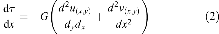
From Figure 2, G is the shear modulus of the adhesive, u (x, y) and v (x, y), are, respectively, the longitudinal and the transverse displacement at any point in the adhesive layer. The corresponding shear stress is given by equation (1):

Differentiating equation (1) gives equation (2):
The shear and the normal stresses in the adhesive layer do not vary through the thickness of the adhesive and are given by equations (3) and (4):
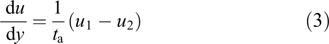

where t a is the thickness of the adhesive layer and (u 1, u 2) present the longitudinal displacements at the bottom of the steel beam and at the top of the FRP plate, respectively. Integration of thermal and hygrothermal model is given by equations (5) and (6):


where ε is the strain, β1 is the humidity coefficient, α1 is the thermal expansion coefficient, Δc is the humidity change, ΔT is the temperature change, P 0 is the prestressing force, and A 1 and A 2 represent area. In calculating the interfacial shear stress, bending of the FRP plate is ignored.
Substituting equations (5) and (6) into equation (4) gives equation (7):

Integrating equations (2) and (7) gives equation (8):

Substituting the longitudinal force from (N1 = −N2) gives equation (9):

The equilibrium of the steel beam in the x direction can be expressed by equation (10):

Differentiating equation (9) and substituting equation (10) gives the governing equation (11):

The solution of this equation has the general solution given by equation (12):

and
Considering the boundary condition due to symmetry, the shear stress at mid-span is zero:

The longitudinal force is zero at the end of the plate, so equation (9) can be written by equation (14):

where B 1 and B 2 are, respectively, given by equations (15) and (16):


Normal stress formulations
The interfacial normal stress is given by equation (17):

where v1 and v2 are the transverse displacements at the bottom of the steel beam and at the top of the FRP plate, respectively, which are given by equations (18) and (19):


Considering the moment equilibrium of an infinitesimal element of the steel beam:


Substituting equation (20) into equation (21) gives equations (22) and (23):


Differentiating equation (17) three times gives equation (24):

Differentiating equation (24) gives the governing equation (25):

The general solution to equation (25) is given by equation (26):
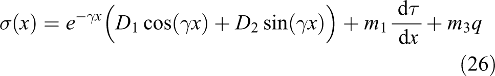

where
At the end of the FRP plate, the bending moment and shear forces are zero. Hence, the boundary conditions can be written by equations (28) and (29):


and
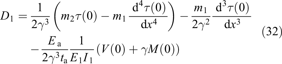
When x = 0, equation (26) derives to equations (30) and (31):


Combining equations (28) to (31) gives, respectively, equations (32) and (33):

Geometric and material properties
We consider in this research that the plate length is L p = 5 m, it is symmetrically linked to its support. The steel beam has a UB122 profile of 533 × 210. A summary of material properties is given in Table 1.
A summary of the material.

Comparison with existing analytical solutions and experimental results
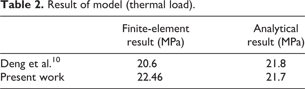
The present prediction of the interfacial edge stresses is compared with that developed by Deng et al. 10 for an applied thermal load (ΔT = 50°C) and with the experimental results done by Jones et al. 21 for an uniformly distributed load (UDL) (q = 60 kN/m2). Figure 3, Figure 4, and Table 2 show an almost exact agreement between results.
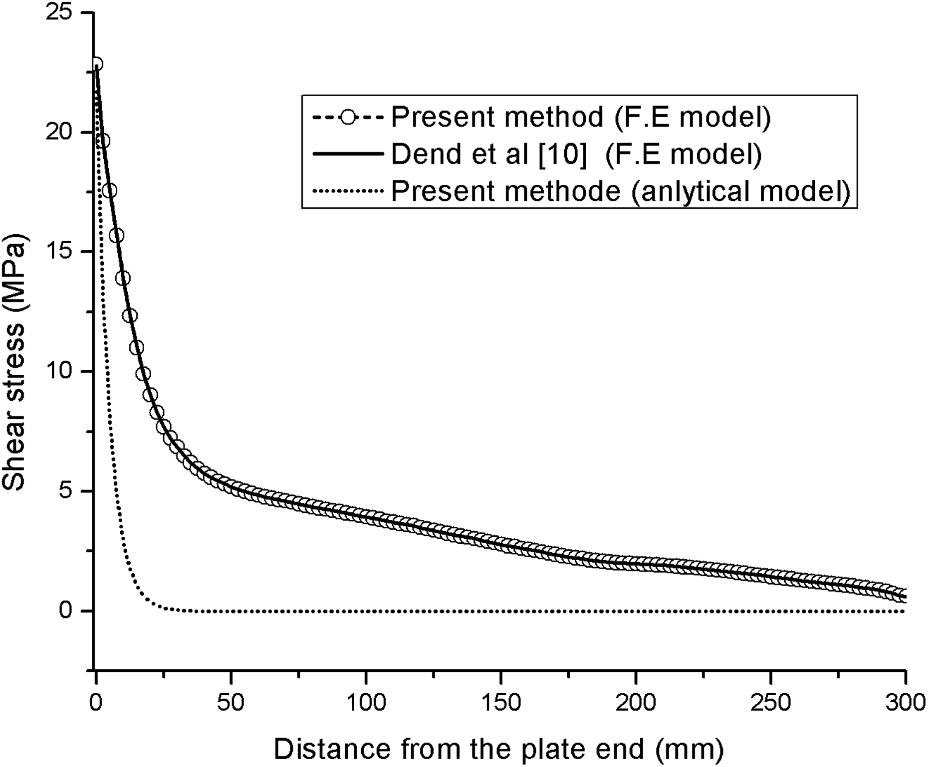
Interfacial shear stress concentration for different solutions (finite element model: ΔT = 50°C).

Interfacial shear stress distribution: Jones et al. 21 (q = 60 kN/m2).
Result of model (thermal load).
Finite element analysis (application of the taper and hygrothermal model)
The 3-D finite element model of the structural components has been employed to validate the results of the above procedure. The geometry of the reinforced beam is shown in Figure 5, in which only one half of the structure is presented, and the steel beam was modeled with shell elements (element S4 R) in the ABAQUS software (Figure 6), a half beam was considered because of symmetry, this half due to the loading conditions. Figure 7 shows the finite element results, where a prestressing force P 0 = 100 kN and hygrothermal load (ΔT = 50°C, Relative humidity (RH) = 50%) are applied. Figure 8 plots the interfacial shear and normal stresses for the steel-plated beam, where a linear taper has been used in both analyses.

Geometry of the plated beam.
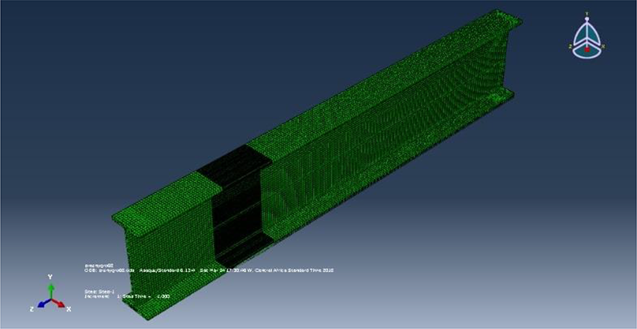
Finite element mesh of geometry.

Stresses concentration (stage 4).
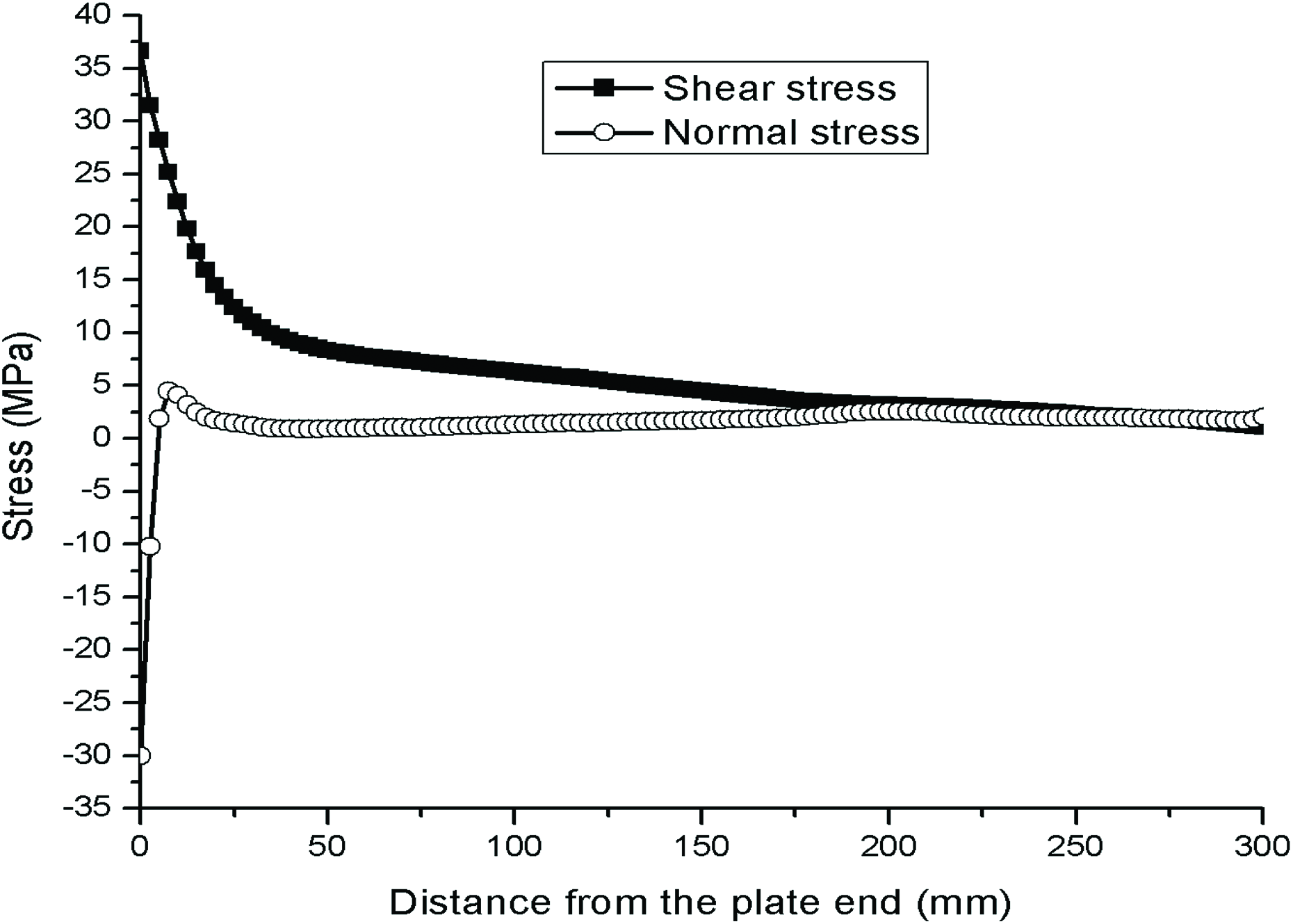
Interfacial stress distribution (stage 4)
Different applied load
In this case, numerical results are presented to study the effect of the linear taper model on the distribution of interfacial stresses in beam strengthened with the composite FRP plate. Figure 9 shows the plots of the interfacial stresses for the following applied:
Stage 1: Prestressing force (P
0 = 100 kN). Stage 2: Thermal load (ΔT = 50°C). Stage 3: Hygrothermal load (ΔT = 50°C, RH = 50%). Stage 4: Prestressing force (P
0 = 100 kN), hygrothermal load (ΔT = 50°C, RH = 50%).

Interfacial shear stress distribution for different stages.
Parametric study
After verifying the accuracy of the present analytical and numerical model, a parameter study is carried out to better understand the effects of various parameters on the interfacial stresses under the coupling of different applied load (stage 4).
Effect of hygrothermal load
The effect of the hygrothermal load on the distribution of interfacial stresses at the end of the laminate is illustrated in Figures 10 and 11, and we notice that the higher values of shear and normal stresses correspond with the higher values of relative humidity and the temperature. Tables 3 presents the maximum values of interfacial stresses for the different values of RH and T for stage 4.

Interfacial shear stress distribution: stage 4 (ΔT constant).

Interfacial shear stress distribution: stage 4 (RH constant).
Hygrothermal effect on interfacial stresses (stage 4).

Linear taper effect
The geometry of the taper is shown in Figure 12, where l is the length of the taper, t end is the thickness at the end of the taper, and t p is the plate thickness.

Geometry of the linear taper.
The parameters of the taper (l) and (t end) are very important. Figures 13 and 14 plot the interfacial shear stress distribution at the tapered end of the plate versus the length of the taper for different tapered end thicknesses. They indicate the beneficial effect of having a thin tapered end and a long taper, the benefit appears when the length of the taper is beyond 500 mm.

Variation of the maximum shear stress (stage 4).

Variation of the maximum normal stress (stage 4).
Effect of the prestressing force (P 0)
In this case, numerical results of the present solution are presented to study the effect of the prestressing force P 0 on the distribution of interfacial stress in a steel beam strengthened with bonded prestressed FRP plate. Four values of P 0 are considered in this study (P 0 =50, 100, 150, and 250 kN). Figure 15 plots the interfacial shear and normal stress for the steel beam strengthened with bonded prestressed FRP plate. From these results, it is seen that increasing the value of prestressing force P 0 leads to high stress concentrations.

Interfacial stresses distribution: prestressing force effect (stage 4).
Plate elasticity modulus effect
The effect of elasticity modulus E 2 on the distribution of interfacial stresses near the end of the prestressed laminate is plotted in Figure 16. For four values of elasticity modulus (E 2 = 110 GPa, E 2 = 210 GPa, E 2 = 310 GPa, and E 2 = 410 GPa), the maximum values of shear and normal stresses are τ = 37.02 MPa and σ = 30.1 MPa for an elasticity modulus E 2 = 410 GPa. So the increasing values of the plate elastics modulus will increase the values of maximum shear and normal stress.
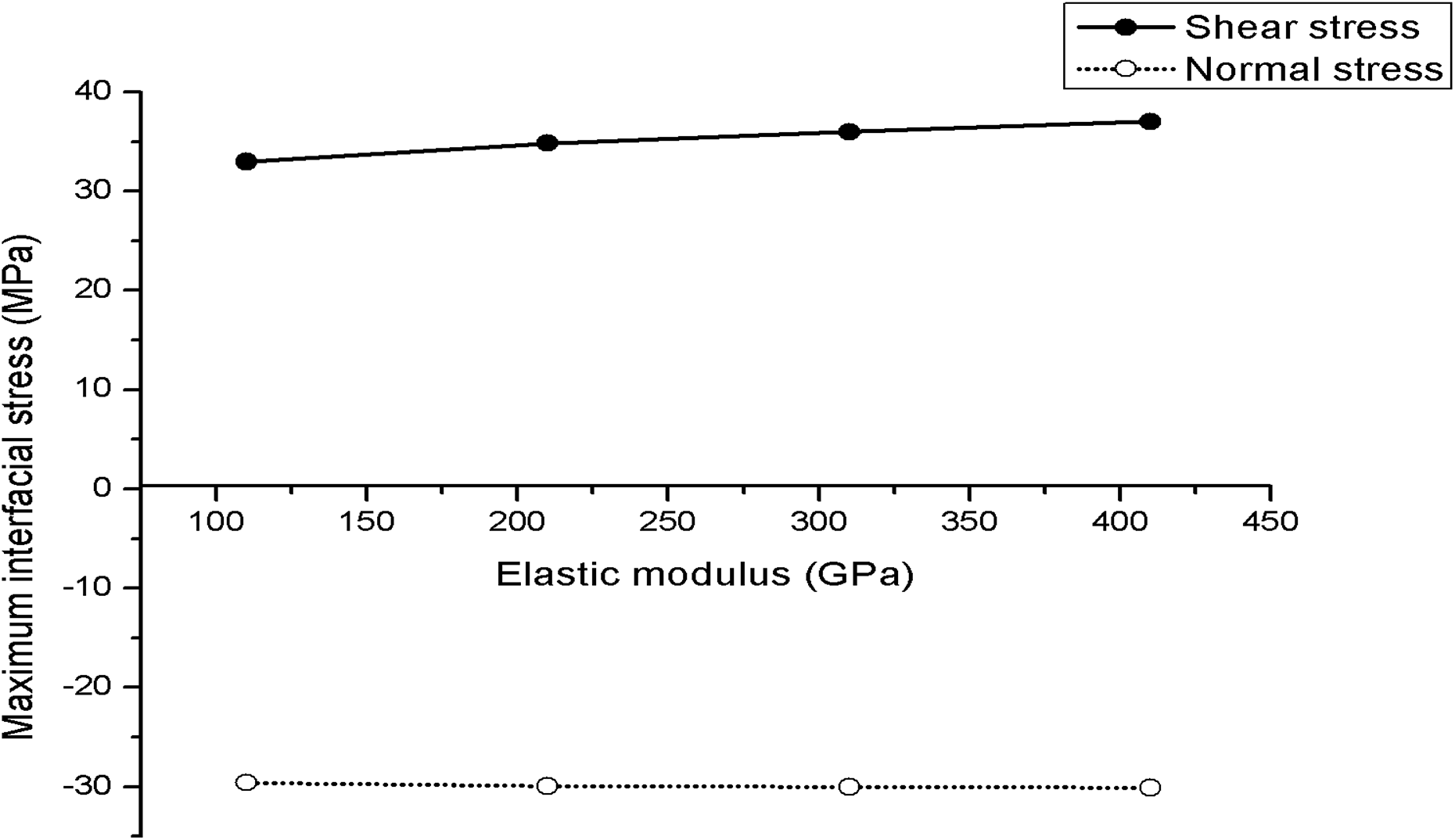
Interfacial stresses distribution: plate elasticity modulus effect (stage4).
Adhesive thickness effect
Figure 17 shows the effect of the thickness of the adhesive layer on interfacial stresses. It is seen that increasing the thickness of the adhesive layer leads to a significant reduction of interfacial stress. Thus, a thick adhesive layer is recommended.

Interfacial stresses distribution: adhesive thickness effect (stage4).
Conclusion
A numerical and analytical solution for determining the shear and normal interfacial stresses between a composite FRP plate and beam submitted to prestressing force and hygrothermal load with a linear taper has been presented. In this research, a finite element model has been employed to validate the results comparatively done by Deng et al. 10 and with the experimental results done by Jones et al. 21 The results obtained from the different analysis is agreed, which demonstrates that the present model is simple and accurate. Some studies of the taper are carried out in this work to better understand the effects of various parameters on the edge interfacial stresses in a structure under different applied load. In this work, our model takes into account the parameters neglected in the previous studies. This work is of paramount importance for designers of materials and structures to optimize their operation and life in the context of sustainable development.
Footnotes
Declaration of conflicting interests
The author(s) declared no potential conflicts of interest with respect to the research, authorship, and/or publication of this article.
Funding
The author(s) received no financial support for the research, authorship, and/or publication of this article.