
Abstract
Composite structures are prone to impact and fatigue loads in service which in turn causes defects such as de-lamination. This affects the dynamic characteristics of the composite laminates such as its Natural frequency, Mode shapes and its damping characteristics. Hence it can be used as a prominent indicator for structural health monitoring. This paper focusses on the use of Kriging based surrogate model for the prediction of delamination in Carbon fibre reinforced epoxy composite panels with an edge constraint. The change in natural frequency and mode shapes of the damaged and undamaged model has been taken as the primary damage indicator for the present analysis. The size and location of the damage were predicted from the developed surrogate models. The performance of the proposed approach has been studied experimentally and compared it with numerical simulation and has been found satisfactory. The surrogate approach reduces the computational time considerably without compromising the accuracy.
Keywords
Introduction
Vibration based delamination detection methods in composites, currently employed for structural health monitoring solutions uses Natural frequency as their basic damage indicator. Other indicators such as the mode shapes and damping parameters if used could enhance their capability of damage detection. Degradation of the structures due to delamination will reduce the strength of the material, ie, its flexural stiffness, which will alter not only the natural frequencies but the mode shapes and damping parameters which could detect the presence of delamination, assessing its size, location and the interface. Delamination occurs in polymer composites due to the poor bonding between the fibre layers. The main disadvantage of using frequency change for damage detection is that while the presence of damage is easily identified through a change in measured frequency, the prediction of the location and the severity of the damage are difficult to accomplish. Here, we use change in modal parameters for determining the location and position of Delamination Damage in composite materials.
To determine the location and severity of the damage from measured changes in frequency, it is necessary to solve the inverse problem, which requires the use of artificial intelligence tools such as Artifi-cial Neural Network (ANN), Kriging, Radial Basis Function (RBF) and other surrogate-assisted optimization techniques.
S.W. Doebling, C.R. Farrar, and M.B. Prime [1] provides a summary of Health Monitoring and Damage detection techniques available for Structural and Mechanical Systems, from the changes in their vibration characteristics. They have particularly addressed the critical issues and the scope of future research in the area of damage identification and quantification. Moreover they stress the need to develop this technology for applications which are beneficial to the industry. Saravanos [2] investigated the effects of delaminations on the dynamic properties of composite laminates. He analysed the effects of delamination on the natural frequencies, mode shapes and modal damping of composite beams. His approach allows the tracing of a number of delami-nations through the thickness of the laminate which represents the layer-wise theory of composite structures.
Hai-yang Gao, Xing-lin Guoa and Xiao-fei Hub et. al. [3] identified crack parameters using a robust stochastic particle swarm optimization (SPSO) algorithm. He used it to find the global optimal solution using a Kriging surrogate model. The accuracy of surrogate model was improved by re-meshing it during updation. He used the maximum probability factor for simplifying the method for crack number identification. Finally, the numerical models were validated with experimental results to assess the robustness and error tolerance of the algorithm. For their analysis, the Hamiltons principle was implemented using Wittrick-Williams algorithm, to develop the free vibration response of a composite beam. The presented theory has been applied for free vibration analysis of composite wings.
Luo and Hanagud [4] modelled composite beams with through-the-width delaminations for obtaining its dynamic behaviour incorporating shear effects, rotary inertia, and bending-extension coupling in its governing equations. Also Non-linear interaction, due to piecewise linear spring models between the delaminated sublaminates were considered. Based on this model, analytical results were obtained. Benvenuti [5] presented a delamination test in fibre reinforced concrete blocks using a continuous-discontinuous extended finite element approach, which takes into direct consideration the mechanical properties of concrete, adhesive and fibre reinforced polymer. He used a combination of orthotropic and isotropic materials. The constitutive behaviour of the concrete is governed by an elasto-damaging constitutive law. Shi-jie Zheng and Zheng-qiang Li and Hong-tao Wang [6] presented a Genetic fuzzy Radial basis function based Neural Network for structural health monitoring of composite laminated beams. The proposed method is a combination of genetic algorithm and fuzzy logic to optimize the centers and widths of the Radial basis function Neural network. The results were found to be robust and promising. Ramazan-Ali Jafari-Talookolaei and Mohammad H. Kargarnovin and Mohammad T. Ah-madian [7] investigated the Dynamic response of a delaminated composite beam with general lay-ups based on the first-order shear deformation theory. He developed a finite element program to obtain the natural frequencies and time responses of the beam. His results were validated with previous studies. Obinna K. Ihesiulor [8] worked on detecting de-lamination with natural frequencies subjected to noise and error using artificial intelligence concepts. He reported that the proposed techniques provided accurate results for structural health monitoring of delaminated beams with error and noise corrupted natural frequency validation data.
Above mentioned papers shows the significance for the development of highly accurate algorithms for structural health monitoring. Here, we present an algorithm which is highly accurate and significantly reduces time for Structural health monitoring of composite plates, data which needed for prediction is found by solving only few forward problem compared with above papers to generate data for inverse problem solving method.
Methodology
Dynamic characteristics of composite plates made of Carbon fibre reinforced epoxy with a non-propagating delaminations of known sizes are selected for the present study. It is assumed that the delamination changes only the stiffness of the plate whereas the mass of the plate remains unchanged. By using the delaminated composite plates fixed at one edge, the effects due to the following on natural frequencies were studied:
The effect of the position of a delamination in X and Y direction.
The size of delamination in two coordinates.
Demonstration of the surrogate modelling technique for solving the inversion problem.
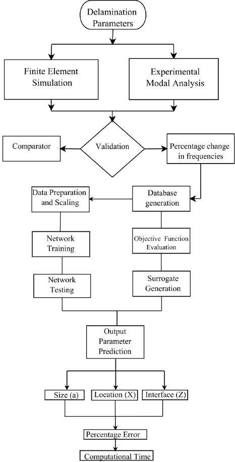
Solution methodology for solving the inverse problem has been illustrated in the Fig. 1. The following surrogate modelling techniques are exploited for determining the accuracy of delamination detection.
Solution Methodology for Solving the Inverse Problem
A large variety of surrogate models have been formulated for use in the prediction problem. Most popular methods used in surrogate-based optimization is provided by Jones [9] and more recently by Forrester and Keane [10]. They include polynomial models, radial basis functions and support vector regression, each method having their own strength and weaknesses. Considering the polynomial models, They are in less complex in modelling one dimensional problems but their demerit lies with high dimensional problems and they possess limited flexibility when dealt with multi-modal landscapes. These problems can be better tackled with using Radial Basis functions which have a level of flexibility that can be easily controlled. Radial basis functions are fundamental to other methods such as Neural Networks and Kriging, both offering increased flex-ibility but at the cost of increased complexity and higher model training costs. Here we limit ourselves to a more detailed discussion of Kriging Interpolation.
Kriging is one method frequently covered in the literature and has been applied to a variety of engineering design problems, including aerodynamic, Forrester and Keane [9], Yoneta et al., [11], structural Booker et al. [12], Sakata et al., [13], multidis-ciplinary Simpson, 2001 [14], and multi objective design problems Keane, [15]. Kriging was initially employed in the field of gold mining and geology Krige, [16] and was later introduced to Engineering by Sacks et.al. [17]. It is Gaussian prediction process which is highly flexible and models uncertainty with great precision to build update points.
Consider the prediction function f (x), used in lieu of the expensive function f(x) as a surrogate. A set of inputs x(1), x(2), x(3),…x(n) and known output y=y(1), y(2), y(3),…y(n) as found by evaluating the true function f(x) was used to build the surrogate. In the current scenario, the inputs are the percentage changes in natural frequency and the outputs are the location, size and interfaces of the delamination. Assume that the approximate function is smooth and continuous, two points x(i) and x(j) are close if x(i)- x(j) is small and the Y(x(i)) and Y(x(j)) are likely to be highly correlated. As x(i) and x(j) move apart the opposite is true. Then the Kriging correlation function is given as follows

From this we create a correlation matrix,

and the covariance matrix

The smoothness of correlation depends on the smoothness parameter ‘p’ and the extent of influence each variable has on the correlation is defined by the width parameter ‘θ’. Maximum Likelihood Estimation (MLE) is used to estimate these parameters. The likelihood for a Gaussian process is as follows,

Maximizing the natural log of the likelihood function.

Taking the derivatives of the above equation for finding the optimal values of the mean μ, and the variance σ2


The natural log of the likelihood function is obtained by combining the above equations,

Maximize the likelihood of prediction to create a prediction y at some new point x, The augmented correlation matrix is given as,

where Ψ~ is the vector of correlation between the observed data and the prediction

Using the optimum parameter values the Kriging predictor can be expressed as,

A flowchart of the solution strategies for the proposed methods is shown in Fig. 2 and a step by step procedure is summarized below:

Methodology Adopted for Surrogate Modelling
A sampling plan is created for defining the experiment. The quality of the plan is achieved by evaluating the candidate solutions by employing Morris Mitchell criterion, which was developed by Morris, M. D. [18].
The data for the above step was obtained by carrying out expensive experiments in the form of Modal analysis of composite plates using Vibration Measurement and Analysis Package (VMAP) software package. Apart from the limited number of experimental solutions, ANSYS Parametric Design Language (APDL) codes were executed for solving the Eigen value problem for determining the natural frequencies of the plates. Block Lanczos was the extraction method employed for determining the first five bending modes of the plate. Thus, the possible candidate designs in the form of damage at particular locations and of definite sizes were generated and analysed both computationally and experimentally.
The Modelling process of surrogates consists of three stages. Firstly, collection and preparation of data and a suitable Modelling procedure was chosen. Secondly, the parameters of the models were estimated and was proceeded to training. Finally the model was tested to determine the accuracy of the developed algorithm.
In the final stage the output parameters such as location, size and the interface were predicted using the developed algorithm and suitable visualisation techniques such as surface plots, contour plots and tile plots were employed for understanding the design landscape.
Artificial neural networks are computational systems that have its working similar to that of the neurons inside the human brain. They are composed of parallel operating elements. A network is denoted in the terms of individual neurons, network connectivity, weights associated with various connection between the neurons and the activation function. The primary structure in a neural network is the neuron (or single-unit perceptron). It is shown in Fig. 3. A neuron performs an affine transformation followed by a nonlinear operation. If the inputs to a neuron are denoted as x1, x2, x3 …. xn, the neuron output y is computed as


Basic Structure of a Neuron
Where, η=w1 x1+….Wn xn +y, with w1, w2,….wn being the regression coefficients.
Here, γ is the bias value of a neuron, and T is a user-defined (slope) parameter. Neurons can be combined in multiple ways. The most common neural network architecture is the multi-layer feed-forward network as shown in Fig. 4.

Two-Layer Feed-Forward Neural Network Architecture.
The function of the network is to map an input vector from one space to another. A set of inputs and their outputs represent the entire network. The mapping is achieved by training the neurons. The learning procedure sets up interconnection weights and the network is trained to make relationships between inputs and their corresponding outputs. The construction of a functional surrogate based on a neural network requires two main steps: i.e., Architecture selection and Network training. The network training can be established as a nonlinear least-squares regression problem for a number of training points. Since, the optimization cost function is nonlinear in all the optimization variables (neurons coefficients), the solution cannot be written using a closed-form expression. A very popular technique for solving this regression problem is the error back-propagation algorithm.
Once training is compete, the network becomes capable of rapid mapping of a given input into required output quantities. This can be used to improve the design. Artificial neural systems can acquire, hold and exploit large amount of experimental information. Adaptability of ANN to its environment is achieved by powerful learning algorithm and self-organizing rules. The ANN has a multilayer architecture known as, feed forward back-propagation network or Multi layer perception (MLP). The MLP has an input layer, output layer and hidden layer. Input layer is fed with an Input vector which is then passed to the hidden layer and finally to the output layer. The neurons are operated by taking the sum of its weighted inputs and passing the output through a transfer function.
On the basis of solution solving methods, neural network can be divided into supervised and unsupervised learning. In first case, a guide is present in order to check whether a system is performing correctly or not. But in the second case, there is no such guide is present and system must rely its on capability by solving sample data. We provide a training set of data so that the system can learn the patterns involved in the data The number of dataset is limited by clustering techniques in which training sets are evaluated and similar datasets are grouped. After the successful training of neural network using the training data set, it can be used for solving back propagation problem. When the behaviour of system changes, the same network can be used to for finding the solution by providing weights which depends on the error of the output.
Numerical simulation was done using the commercial Finite element program ANSYS 14.5 for both the healthy and delaminated carbon fibre reinforced composite plates in order to investigate their vibration behaviour. The results obtained from finite element analysis were employed to solve the forward problem and generate data of variation of natural frequency for known delamination parameters. Analysis is carried out using 8 noded 3-D element (SOLID185), which have three degrees of freedom per node such as translations along the X and Y axes and the rotation along the Z axis. Delamination will affect the stiffness matrix alone, but the mass matrix remains unchanged. Theoretically, damage is assumed to affect the stiffness matrix of the system. Stiffness is considered for all elements for the healthy plate. Effects of stiffness has been applied to damaged elements. The composite layers were defined using shell section which is shown in Fig. 5. This has been applied to the model at the time of meshing. The delaminated plate model created by merging all nodes other than delaminated ones, For that Contact elements (TARGE 170/CONTAC173) were employed between the laminates to avoid separation and inter-penetration due to nodes at the surface of lamina, which helps two separate plates constrained to move together. To build the model, a mesh analysis was initially carried out, to determine the convergence of the numerical results. The first simulation was performed for the healthy plate model, it was then compared with the theoretical results and is found satisfactory. The Fig. 6 shows the mode shape corresponding to the natural frequency of the healthy plate. In Finite Element model for the delaminated plate, overlap between nodes in the de-laminated region are allowed but are left separate.

Fibre Orientation Display for [0/90/90/0]s Laminate.
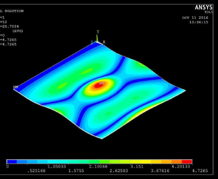
Mode Shape of the Composite Plate at 20.70 Hertz
The Finite Element mesh employed for the model consist of 100 elements along the length, 5 elements across the width and one for each layer of the 8 ply laminate. The result obtained from the healthy model is consistent with that from theoretical results. ANSYS batch mode simulation is employed for eigenvalue modal analysis, from which natural frequencies of the delaminated plate is obtained. The extraction method employed for obtaining natural frequencies of the first five bending modes is Block Lanczos, ignoring the torsion and in-plane bending modes. The natural frequencies of the healthy and delaminated carbon fiber/epoxy composite plates were computed. The results obtained from the Finite Element model have been used to compared with theoretical results for validation purposes.
The results obtained from simulation were compared with those of the previous work by Ihesulor et. al. [8] and has been represented in Table 1 and Table 2 respectively. The Table 3 gives the error between the current and previous studies.
Results obtained from simulation in ANSYS APDL

Natural Frequencies for Delamination along different Interfaces (in Hertz) as per Ihesuilor et. al.

Comparison with Prevous Work in Terms of Percentage Errors in Natural Frequencies

The governing differential equation of a rectangular composite plate with mid plane symmetry is given by Vinson et. al. [19] using the following equation

As per Euler Bernoulli Theory also regarded as the classical theory, the transverse-shear deformation in the plate is neglected. Also, for natural vibrations the load (the forcing function) can be ignored and the resulting equation is,

This equation yields all of the natural frequencies for plates with any boundary conditions. The deflection function since it satisfies all boundary conditions may be written as,

where ωmn is the natural circular frequency in radians per unit time. Substituting Equation 13 into Equation 12, non-trivial solution exists only when

The lowest natural frequency i.e., the fundamental natural frequency which occurs when m=n=l, in cycles per second (Hz) is given by,

The data obtained from procedure described above is employed to fit a fourth-order polynomial equation using Matlab Surface fitting tool. The number of dataset taken from FE model simulations were 125. The fourth-order polynomial equation represents the variation of responses in the form of percentage changes in natural frequencies corresponding to the delamination location and size. The expression below illustrates the model involving the changes in natural frequencies.

where the coefficients,
p00= 1.118
pl0 = −0.0002941
p01 = 1.533
p20 = −1.966e-08
p11= 0.0003427
p02 = −6.951
p21=9.563e-08
pl2 =−0.0004401
p03 = 4.999
For predicting the delamination size and location at a known interface as shown in Fig. 7, considering only mid-plane delamination, 125 Finite Element models equally spaced at gaps of 5% are run in batch process of the total plate length and having normalized sizes ranging from 30% to 70% at gaps of 2% (30:5:70). The 125 generated datasets were randomized using the MATLAB Sampling script. 125 simulations were run in ANSYS, to generate the true function. The equation were fitted using the non linear surface fitting toolbox in Origin Software. The fitted results is then used as the objective function for prediction. The predicted results were in the form of contour plots representing the changes in frequency with respect to the location and size of damage. The Percentage change in frequency for Mode 1 has been shown in Fig. 8 followed by Mode 2 and Mode 3 in Fig. 9 and Fig. 10.

Schematic Diagram of Composite Plate considered for the Two variable problem

Mode 1

Mode 2

Mode 3
A multilayer feed forward back propagation neural network with optimum network architectures are obtained for the different scenarios by trial and error. Almost all the network structures give a root mean square error (RMSE) of 0.0001 and 0.001 in training and test data respectively. The average time taken for the network training is 77 s. The prediction results of ANN with 125 and 20 datasets for network training and their corresponding errors between the prediction and the actual datasets have been tabulated. %(E-X) and %(E-a) stand for the percentage error between actual and predicted values for location and size respectively. Delamination prediction via Kriging takes an average time of 315 s. It is shown that ANN prediction with 125 datasets yields excellent results with error less than 0.02%.
However, as the training dataset decreases, the prediction error increases for all the test cases. With 125 training datasets, results are somewhat satisfactory with maximum error of 3.06% while ANN technique becomes almost inefficient and unsatisfactory with 125 and 10 datasets as evident in prediction errors as high as 4.57 and 40% respectively for the test cases. Therefore, with datasets as small as 10 and 15, ANN fails to give reasonable delamination prediction.
The MATLAB toolbox for Artificial Neural Network was utilised for configuring the networks of different architectures and the training algorithms were suitably selected. Since there exists no hard and fast rule for the selection of network architectures, different configurations were selected and trials were conducted to minimise the RMSE Error in the network output. A description of the training performance of Artificial Neural Network with reference to the mean square error is given in Fig. 11 and the training state is shown in Fig. 12.

Plot displaying Training Performance of Artificial Neural Network

Plot Displaying Training State
In the previous studies, computational time were not taken into account as a performance indicator for the algorithm. But our best efforts were made to select a suitable architecture with minimum computational time. The following are the steps implemented for solving the inversion problem using Artificial Neural Networks:
The percentage change in natural frequency data were splitted into three parts in the form of training, validation and testing. About 70% of the data were used as training to learn the behaviour of the plate dynamics. Remaining data were again split 15% each for validation and testing process.
A suitable network architecture were selected using trial and error method using the nftool command.
Inputs corresponding to known values of outputs are fed into the network and is tested for the accuracy of the results in the testing process.
After the testing process, the problem is validated by feeding unknown inputs into the neurons and the predicted output is obtained.
The CPU Time is calculated simultaneously which is then used to compare with the efficiency of other algorithms.
The regression plot obtained from ANN is shown in Fig. 13, and the predicted results were compared with the actual ones in Fig. 14.

Regression Plot for Artificial Neural Network Prediction

Predicted Results Versus the Actual Ones
Kriging algorithm is applied directly on ANSYS model of the objective function using a population of 125 members over 10 to 20 samples per iteration shown in Table 3. The optimization algorithm calls ANSYS to create data for each member of the population selected in each iteration. The forward problem takes a total CPU run time of 3 h. This method is limited to 125 function evaluations to be consistent with the number of function evaluations used to create the database for surrogate modelling. The results of Kriging model without surrogates (125 evaluations) and with surrogates (20 function evaluations) were compared. In most test cases, prediction error of less than 1% is observed with a maximum error of 3% for the 125 function evaluations. However, prediction results are very poor with 10 function evaluations, hence it is needed to increase the sample size to make the surrogate more accurate.
Surrogate assisted optimization (SAO)
Online optimization problems involve tasks that are solved within split of seconds or minutes whereas offline optimization tasks are processes that take hours to arrive at optimum solutions. We propose a methodology that converts offline optimization to online optimization with the use of surrogates. This is because the simulation of natural frequencies of laminated composite plates demands optimization of expensive objective functions which makes them inefficient due to huge volume of calculations and consumes a lot of time. Hence, surrogates are built and integrated with the optimizers to solve the optimization problem. Many different surrogate modelling techniques like Kriging, ANN have been developed and applied to prediction problems. Kriging models is considered as an effective surrogate model for the problem under consideration.
In the ANN approach, an objective function model is constructed to solve the prediction problem via surrogates. A script is developed in Matlab which takes the percentage change in natural frequencies in the form of mathematical models from the database corresponding to known delamination location, size and interface as inputs to the network. During the process, the surrogate model is first trained using training data sets and then a test set is given to measure its effectiveness for the unknown data. The final approximation model and corresponding weights are saved and used for the optimization process. But, in the Kriging process, sampling plans are developed and they are ranked according to the Morris-Mitchell criterion so that a few points in a design space can be selected to represent all possible points efficiently. The optimum sampling plan for this problem has been represented in Fig. 15.

Optimum Morris-Mitchell Sampling Plan
The main objective of this part is to check the amount of errors in the obtained frequencies for which the developed techniques can account. It should be noted that the ANN surrogate models have been validated with the experimental results and reported in a paper published by Ihesulor et. al. [8]. Therefore, this study is a step forward to further evaluate the performance of these algorithms in the presence of artificial errors and noise. The ANN model used for prediction is developed with 125 training datasets and the test cases are chosen from data not used during the network training. The surrogate models used for the optimization process is also developed with the same 125 datasets. The error we added artificially is the difference in computed percentage changes in natural frequencies (dFi) by FE model and the actual percentage change in natural frequencies to which the delamination signature is to be determined as defined in Equation 18. We added the same amount of errors across all frequency modes.

Given any measured frequencies (dFMi) for which the delamination signature is to be ascertained, a certain amount of artificial error (E) is added using Eq. (18) to obtain (dFMie) with artificial errors (dFMie) is the measured percentage change in natural frequencies for the ith mode with errors; E = error % ranging from 0.1% to 3%.
The computational time for various functions used in the Kriging algorithm were obtained and the total computational time was calculated by summing the individual run time in seconds. It was found that a number of functions were called multiple times by the algorithm and this was incorporated in the total run time. This has been illustrated in Table 3. This time has been compared with previously used algorithms such as ANN, as proposed by [8]. This work also refers the works of [6] A genetic fuzzy radial basis function neural network for structural health monitoring of composite laminated beams and [20] on the comparison of three vibration-based inverse algorithms for detection of delamination in composite beams. This includes a graphical method, ANN and Surrogate Assisted Optimization.
In order to validate the FEM Results in predicting delamination in structures, Carbon fibre reinforced epoxy plates were manufactured and tested. They were fabricated with Owens corning Thermopreg commingled Polypropylene Glass Fabric Woven Rowing (Owens Corning Composite Materials). The size of the plates were 300mm x 300 mm x 2.5 mm with the stacking sequence [0, 90, 45, −45]s. The specimens were cured at room temperature prescribed by the manufacturer. After curing, the laminate panel.
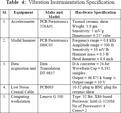
The specimen is clamped in a test rig and excited by Modally tuned hammer (PCB Piezotronics, Type 086C03) as shown in Fig. 16. The vibration response is registered by using a Triaxial ceramic shear Accelerometer (PCB Piezotronics Type 356A01). The analog signals obtained from the transducer are amplified and converted to digital form by using the data acquisition unit (Data Translation, DT-9837). The specifications of the hardware used for the experiment is mentioned in Table 4. The responses were recorded using the Vibration Measurement and Analysis Package (VMAP) version 4.5. The results of Experimental modal analysis were compared with Finite Element Analysis along with that of previous work is tabulated in Table 5 and are found to be satisfactory.

Setup for Experimental Modal Analysis
Computational Time in Seconds Versus Number of Samples

Vibration Instrumentation Specification
Comparison of Experimental Modal Analysis(EMA) results with Ihesiulor et al.[8] and Finite Element Analysis (FEA) Results for healthy plates

The surrogate approach reduces the computational time considerably without compromising the accuracy. The proposed scheme is then proved to be effective and promising for delamination identification in composites. The results show that the identified delamination locations and sizes are in good agreement with the actual ones. Also this method proves to be superior to Artificial neural networks (ANN) in terms of number of samples and accuracy of prediction. The performance and comparison of the algorithms were studied with varying the number of samples using the sampling plan and different surrogate modelling approaches ANN and Kriging. The computational method adopted for the inversion problem also be used to determines the interface in spite of size and location of delamination using changes in measured natural frequencies before and after damage. The algorithm successfully performed delamination detection with limited number of samples. The conclusions from this research could be thus summarised as:
Inverse algorithms for delamination predictions are successfully developed and have been compared with numerical and experimental results. Results show that the proposed methods are capable of solving the problems with limited datasets often with prediction errors within 3%.
The implementation of prediction techniques for delamination detection in composite plates require large numbers of samples and thereby making the computationally expensive. The present study focused on improving the accuracy of delamination detection results by minimising computational cost using surrogate approach.
This method proves to be superior to Artificial neural networks (ANN) in terms of number of samples and accuracy of prediction. A kriging surrogate model with Gaussian kernel function is used as the underlying approximation scheme while an improved rate of convergence is achieved by increasing the number of samples. Moreover, unlike the ANN Surrogate models which usually requires large training datasets, kriging surrogate models requires only a fraction of the data required for prediction. While, K-means clustering is commonly employed to reduce the size of datasets in ANN, in Kriging surrogate models, Morris Mitchell sampling plan has been used to reduce the data.
For solving a 2-variable problem, ANN algorithm was proved to be effective. However for predicting higher variables, surrogate assisted optimization using Kriging surrogate models holds good as in the case of defining damage using 4-variables in composite plates.
The kriging approach without adopting surrogate models proved to be expensive and time consuming, but no compromise on accuracy was found. A trade off between accuracy and the time was achieved by implementation of Kriging surrogate models for this damage detection problem.