
Abstract
The filling pressure control is one of the key technologies of wet clutches. Pressure sensor is a key component to realize the closed-loop control of the filling pressure. However, with the working hours increasing, the pressure sensor is prone to be faulty. To ensure the filling performance of wet clutches, this article investigates a pressure sensor fault diagnosis and fault-tolerant control strategy for the filling phase of wet clutches. First, the dynamic model of a hydraulic clutch control system is established where the clutch pressure sensor fault is considered. Second, the optimal filling pressure reference trajectory is constructed by Pontryagin’s minimum principle. In the fault-free case, a feedback controller is designed to track the desire pressure trajectory with an observer estimating the unmeasurable state of the system. Third, an adaptive observer is constructed to estimate the pressure sensor fault. Based on the estimated sensor fault information, a pressure sensor fault-tolerant control strategy is proposed for the filling phase of wet clutches. Simulation results show that the proposed fault-tolerant controller can realize smooth and precise clutch-filling control with pressure sensor fault.
Introduction
Wet clutches are widely used in automotive transmissions (AT) and dual-clutch transmissions (DCTs). After the clutch is engaged, accurate clutch pressure control is one of the key technologies for vehicle starting or shifting.1–3 Before the clutch is engaged, it is necessary to carry out clutch-filling control, in which the clutch piston moves from the initial position to a point where the clutch packs just come to contact while the transmission torque is zero. Clutch-filling control is one of the key technologies of wet clutches as a preparation for the vehicle starting and shifting.4,5 Poor clutch-filling performance will seriously affect the starting or shifting performance of the vehicle. To realize precise pressure control during the clutch-filling phase, pressure sensor is often equipped on a product vehicle. However, with the increase in working hours, the pressure sensor is prone to various faults. Typical pressure sensor faults include bias fault, constant output fault, and drift.6,7 The failure of pressure sensor will seriously affect the clutch filling operation which may further lead to a discomfort gear-shift performance. Therefore, it is vital to diagnose the pressure sensor fault and design a fault-tolerant controller for the filling phase of wet clutches.
Several control algorithms have been proposed for the filling control wet clutches. The iterative learning control method was developed for the filling of wet clutches with both pressure sensor and clutch position sensor. 8 The optimal clutch-filling reference pressure trajectory was designed based on dynamic programming. 9 In addition, a sliding-mode controller has been proposed to achieve robust clutch-filling pressure control with the model uncertainty. 10 Hao et al. 11 proposed an adaptive generalized predictive control algorithm to track the clutch-filling pressure trajectory with the model error. However, previous studies seldom consider the influence of pressure sensor fault.
There is little literature reported in fault diagnosis for pressure sensor of wet clutches. Traditional sensor fault diagnosis is based on limit checking and trend checking of the measured signal. Before sensor fault occurs, the measured signal ranges from its lower and upper bounds, while the measured signal violates the signal tolerances when the sensor becomes faulty. However, the traditional sensor fault diagnosis method is a roughly sensor fault detection mechanism, and the fault magnitude information is unable to obtained, which lays a problem for active sensor fault-tolerant control (FTC). Recently, state estimation-based methods have been widely investigated for sensor fault diagnosis. An observer was designed to detect the pressure sensor fault in a DCT vehicle, and the sensor constant output fault can be detected timely. 12 To view the fault signal as a new state, augment system methods have been proposed to estimate the sensor fault magnitude. An unknown input observer-based method has been proposed for sensor fault estimation by Gao et al. 13 However, only time-invariant fault magnitude can be estimated while failed to estimate the time-varying fault information. Sliding-mode observer-based fault estimation method has the ability to estimate time-varying sensor fault after series of transformations of the original system.14,15 Adaptive observer-based fault estimation methods have been widely applied in engineer problems during the simple structure of the adaptive observer. Wang and Daley 16 developed an adaptive observer-based technique to diagnose actuator fault, which can estimate time-invariant actuator fault signal. By transforming the sensor fault as actuator fault, a fast adaptive fault estimation method was designed to enhance the performance of sensor fault estimation.17,18
There are typically two strategies to achieve active sensor FTC, which are hardware redundancy and analytical redundancy. The concept of sensor hardware redundancy is to use several sensors to measure the same signal simultaneously. In addition, when one of the sensors occurs fault, the healthy sensor is used for the close-loop control.19,20 However, due to the cost and structure limit, it is impossible to equip redundancy sensors. Therefore, several researchers have investigated analytical redundancy-based sensor FTC methods.21,22 Angular displacement sensor FTC for the gear-shifting engaging process of an automated manual transmission has been achieved by estimating the angular velocity using a sliding-mode observer. 23 Adaptive neuro-fuzzy inference system-based soft sensors were designed as a backup of the faulty sensors. Once the fault is detected, the soft sensor can replace the faulty sensor to guarantee that the system avoids collapse. 24 Kommuri et al. 25 designed a high gain observer to estimate the motor speed, and the estimated speed is used for the controller to achieve the speed tracking control objective in the case of sensor fault. Sensor fault-tolerant tracking control objective for an electrohydraulic actuator was achieved by using the estimated fault information. 26
The limitations of the existing studies can be summarized as follows. The accuracy of the existing fault diagnosis method for the clutch pressure sensor needs further improved. In addition, the sensor fault-tolerant strategy should be developed so as to ensure the stability and reliability of the clutch system. The main contributions of this study are as follows: (1) An adaptive observer is designed to estimate the pressure sensor fault, and (2) the pressure sensor active fault-tolerant controller is established with the help of the estimated sensor fault information. Once the sensor fault occurs, the controller can use the reconstructed pressure signal to achieve good filling performance of wet clutches.
The rest of the article is organized as follows. In “problem formulation and preliminaries” section, the problem is formulated, which gives some necessary assumptions, lemmas, and the research objectives. In “main results” section, the filling pressure reference trajectory is designed, a feedback controller is developed for the fault-free case, and the sensor FTC strategy is proposed in the case of sensor fault. Simulation results are shown in “simulation results” section. Finally, the conclusion remarks are provided in “conclusion” section.
Problem formulation and preliminaries
Figure 1 shows a simplified schematic diagram of a hydraulic clutch actuation system in seven-speed DCTs.27–29 The clutch pressure is controlled by a variable force solenoid (VFS). As shown in Figure 1, when the solenoid magnetic force Fmag exerted on the valve spool is large enough to push the valve spool to the right, the supply pressure ps is connected with the clutch chamber, and the clutch chamber pressure pclt will increase to a desired value. When the solenoid force is about zero, the spool is moved back to the left, and the pressurized fluid in the clutch chamber can be discharged to the tank. The valve is an overlap valve, and the land width is greater than the port width, which means that there is no fluid flow when the spool is in the neutral position. There are two orifices R1 and R2 in the VFS, which are viewed as pressure restrictions in the pressure port going to the piston chamber. The feedback pressure on both sides of valve may improve the dynamic behavior of the spool. When the clutch pressure reaches the target level, the solenoid magnetic force is balanced with the feedback pressure and the spool return to the neutral position. However, due to the fluid leakage in the clutch chamber, the spool displacement is slightly over the neutral position when the clutch chamber pressure is stable.
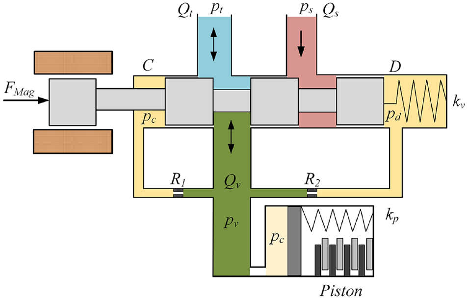
Diagram of a hydraulic clutch control system.
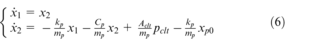
During the filling phase of the wet clutches, the dynamic equations can be described as
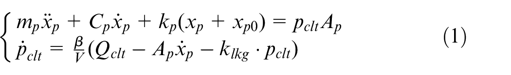
where
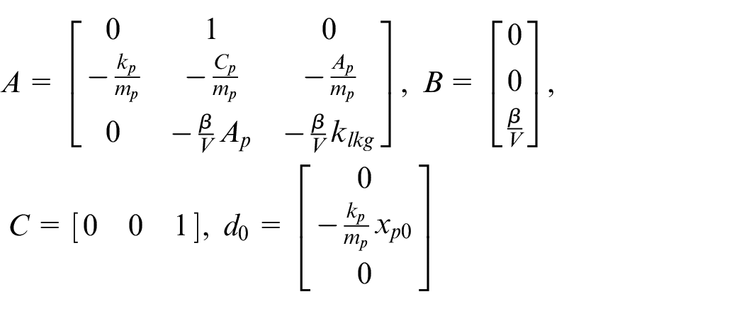
Denoting the state variables as
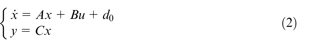
where
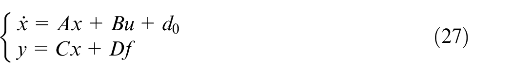
In the actual working process, the clutch pressure sensor works in a bad environment. Furthermore, with the working hours increasing, the pressure sensor is prone to faults. When the clutch pressure sensor occurs fault, the system equation (2) is deteriorated as

where f denotes the sensor fault signal, and
To conveniently design the sensor fault-tolerant controller, the following assumptions and lemmas are given.
Assumption 1. The fault signal and the first order derivate of the fault signal are bounded, which can be expressed as
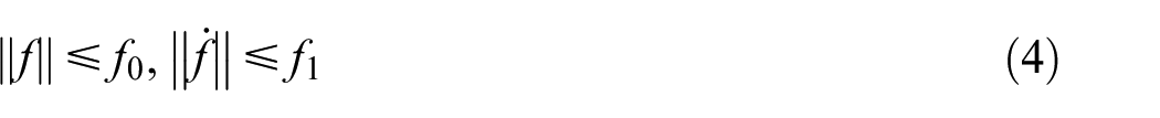
where
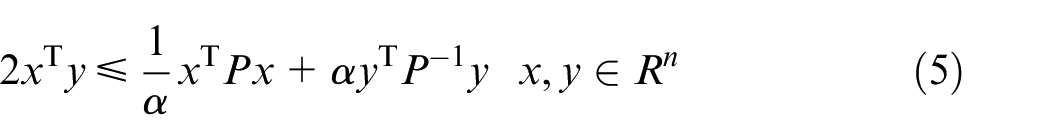
Lemma 1. For a scalar
Normally, when the clutch pressure sensor is healthy, a basic controller should be designed to stabilize the system equation (2). Moreover, the control law must ensure the clutch pressure is consistent with the target reference pressure trajectory. In the sensor fault case, as shown in equation (3), a sensor fault-tolerant controller must be developed to compensate the sensor fault. This sensor FTC law is designed based on the fault signal, which can be estimated with an adaptive observer. The topics above are discussed in detail in the following sections. The proposed clutch pressure sensor FTC architecture is shown as Figure 2.
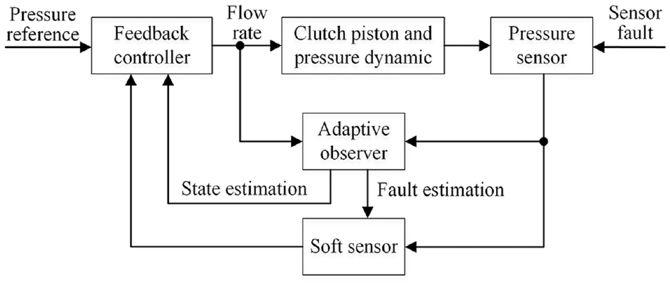
Clutch pressure sensor FTC architecture. FTC: fault-tolerant control.
Main results
Filling pressure reference trajectory design
The clutch piston dynamics during the clutch-filling operation can be expressed as
where
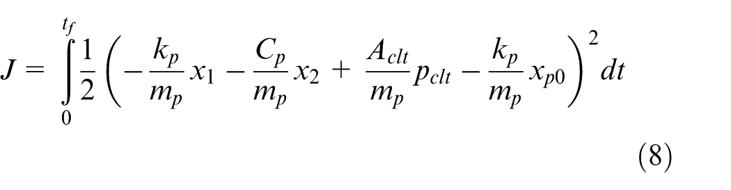
The optimal filling pressure can be obtained based on Pontryagin’s minimum principle. The objective is to minimize the energy consumption during the filling phase; the performance index is chosen as
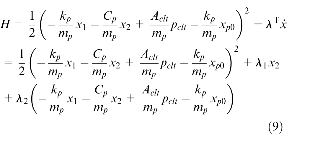
The Hamiltonian function is formed as
According to the optimal control theory, the optimal solution is governing by the state equations
and the co-state equations
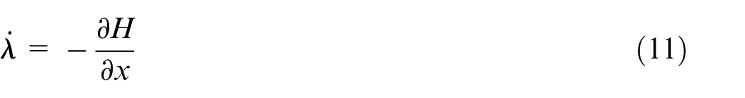
as well as the control equation
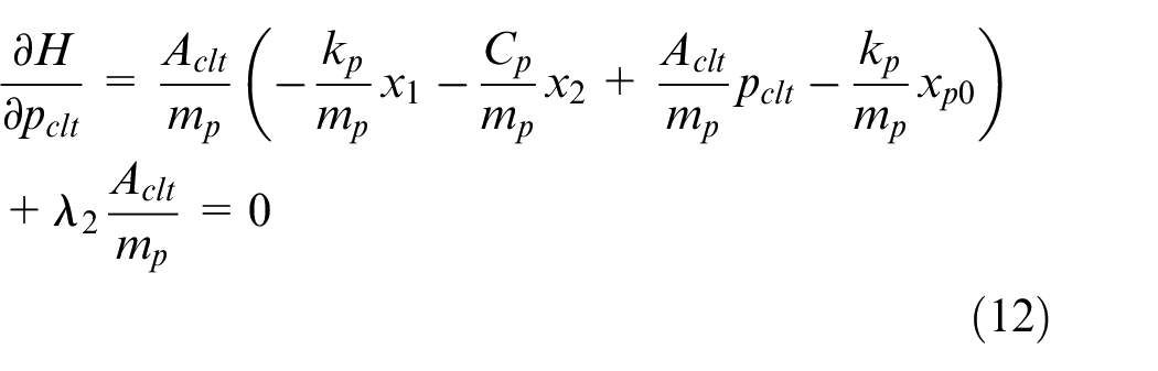
From equation (12), the optimal filling pressure is deduced as follows
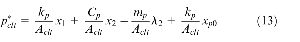
Substituting equation (13) into equation (11) gives
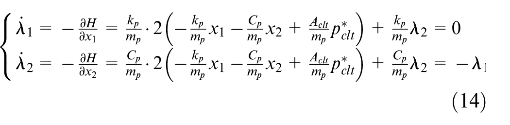
From the first order differential equations (6), (13), and (14), the analytic solutions can be derived as follows
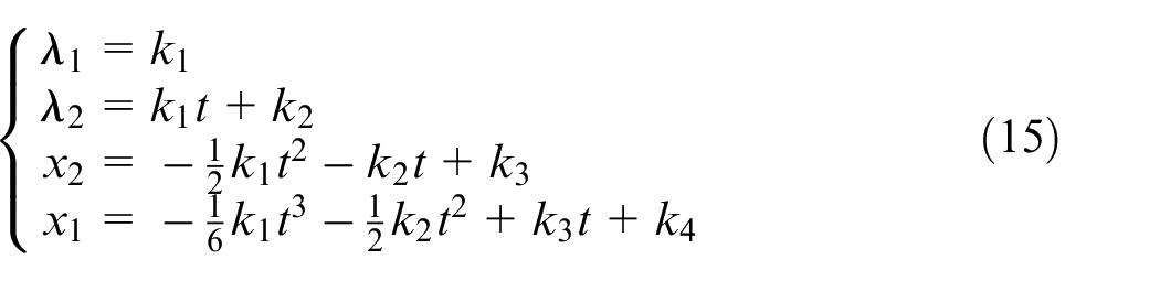
where
The optimal filling pressure trajectory can be expressed as
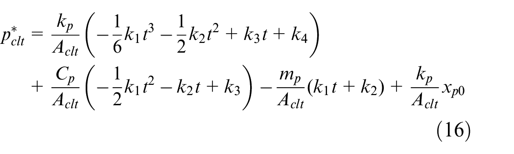
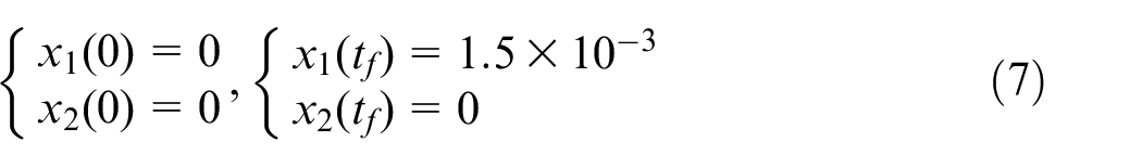
According to the initial conditions and final conditions as expressed in equation (7), the parameters in equation (15) can be solved. Therefore, the optimal clutch-filling pressure trajectory can be obtained as shown in equation (16).
Basic controller design for the fault-free case
For accurate clutch-filling pressure control, the dynamic of the clutch piston and the dynamic pressure in the clutch chamber should be considered. In the fault-free case, the overall system is expressed as
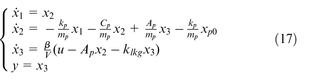
where
The pressure track error is denoted as

where
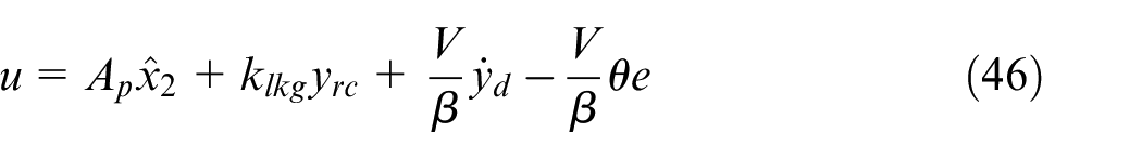
The controller is designed as
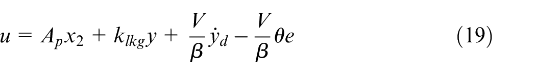
where
Substituting equation (19) into equation (17) gives
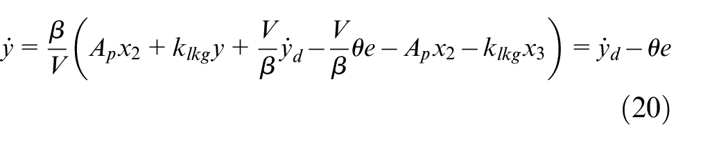
Therefore, the error dynamic is

According to equation (21), with the controller equation (19), the pressure tracking error of the system equation (17) is asymptotically converged to zero. In addition, the explicit relationship between the input and output of the system can be obtained by first differentiating of the system output. Therefore, the system equation (17) has a relative degree of 1. The clutch piston displacement and velocity can’t be observed directly from the input–output relationship, which represents the internal dynamics of the system.31,32 The internal dynamics is expressed as
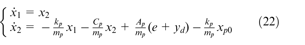
According to equation (21), the tracking error is bounded, and the designed filling pressure reference trajectory is bounded as well. It is obviously that all the eigenvalues of the system matrix of the system equation (22) have negative real parts. As a result, for bounded input
It can be noted that in the controller equation (19), the clutch piston velocity information is needed. However, there is no such a sensor to measure the piston velocity in a product vehicle. To this end, an observer should be designed to estimate the clutch piston velocity. With the estimated piston velocity, the controller is modified as
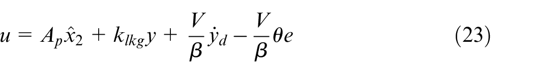
where
It is obviously that the system equation (17) is observable by the rank checking method. Considering the state-space form of the system equation (17), an observer is designed as
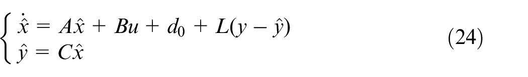
where
The state estimation error is

The dynamics of the error is
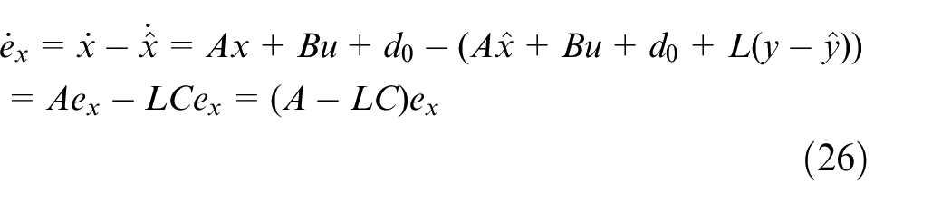
By appropriately designing the gain matrix L, and making (A-LC) be a Hurwitz matrix, the state estimation error will asymptotically converge to zero. Therefore, the observer equation (24) can be used to estimate the state of the system equation (17). The estimated piston velocity
Sensor fault-tolerant controller design
In practice, it is imperative to diagnose the clutch pressure sensor fault timely and accurately. Moreover, fault-tolerant controller should also be developed to guarantee the stability and reliability of the clutch control system. Fault estimation methods are potential in engineering application because both the time when the fault occurs and the magnitude of the fault can be obtained simultaneously. In this section, an adaptive observer-based clutch pressure fault estimation method is provided. Based on the estimated fault information, the sensor FTC strategy is proposed.
As described in “Problem formulation and preliminaries” section, when the clutch pressure sensor fault occurs, the system equation (17) is deteriorated as
where
The sensor fault is transferred to the actuator fault by using the augment system methods.
33
In addition, a new variable should be constructed appropriately. The constructed new variable

where
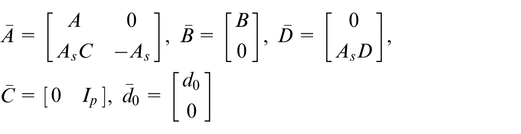
Take the state of equation (27) and the new variable
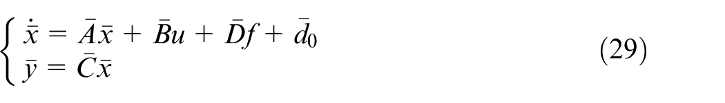
where
The adaptive observer for the augment system equation (29) is constructed as
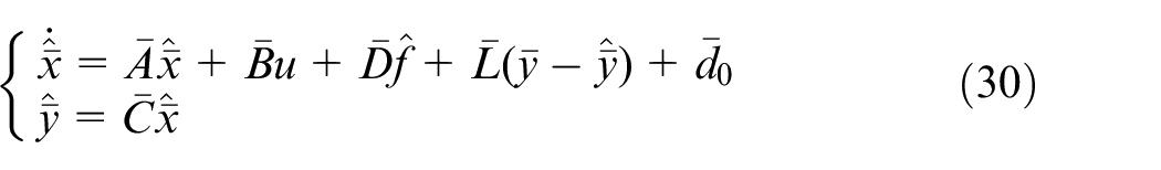
where
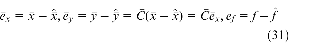
The state estimation error, output estimation error, and fault estimation error are expressed as
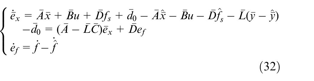
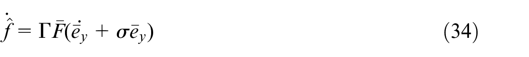
The derivative of the state estimation error and fault estimation error is derived as
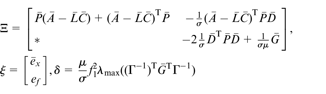
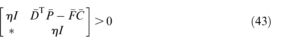
Theorem 1. For given scalars
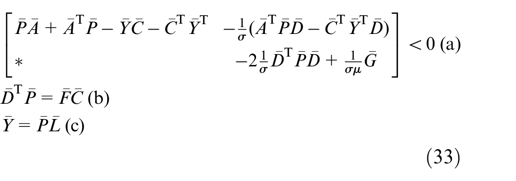
where ⋇ denote the symmetric elements in the matrix; then, the fault estimation algorithm
can guarantee the state estimation error and fault estimation error converge gradually to a small set, where
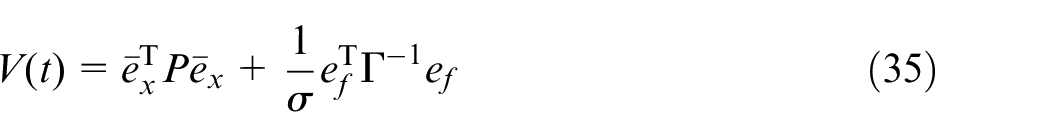
Proof. The Lyapunov candidate function is chosen as
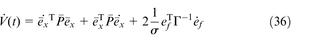
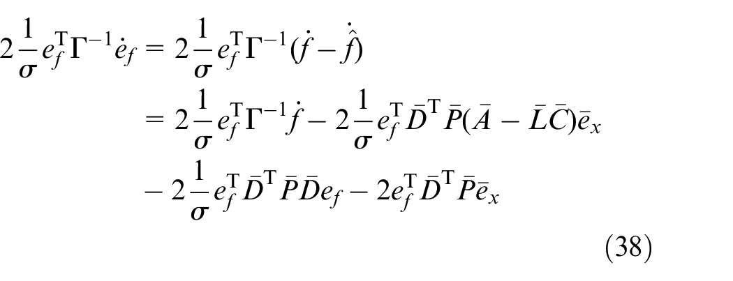
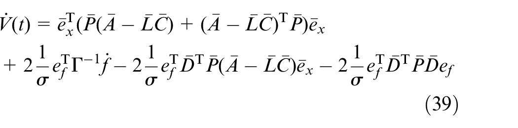
The derivative of the equation (35) is expressed as
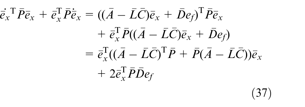
Using equations (31) and (32), one can obtain that
From equations (32) and (34), it is easy to show that
Therefore,
According to Lemma 1, the following inequality holds:
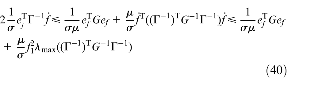
Substituting equation (40) into equation (39) yields

where
When

where
It follows that
The equality constraint in equation (33b) can be transformed as the following optimization problem.
Minimize
The gain

Based on the fault estimation information by the proposed adaptive observer, the sensor signal can be reconstructed. While the sensor fault occurs, the sensor is masked and the reconstructed soft sensor is used for the clutch-filling pressure control. By replacing the faulty sensor with the soft sensor, there is no need to change the parameters and structure of the controller.
When the sensor fault occurs, the reconstructed soft sensor is as

The fault-tolerant controller is expressed as
Simulation results
Sensor fault estimation analysis
The main parameters used in the study are shown in Table 1. Some of the parameters are obtained by measuring the wet clutches, and some are provided by the supplier.
Main parameters for system dynamics.
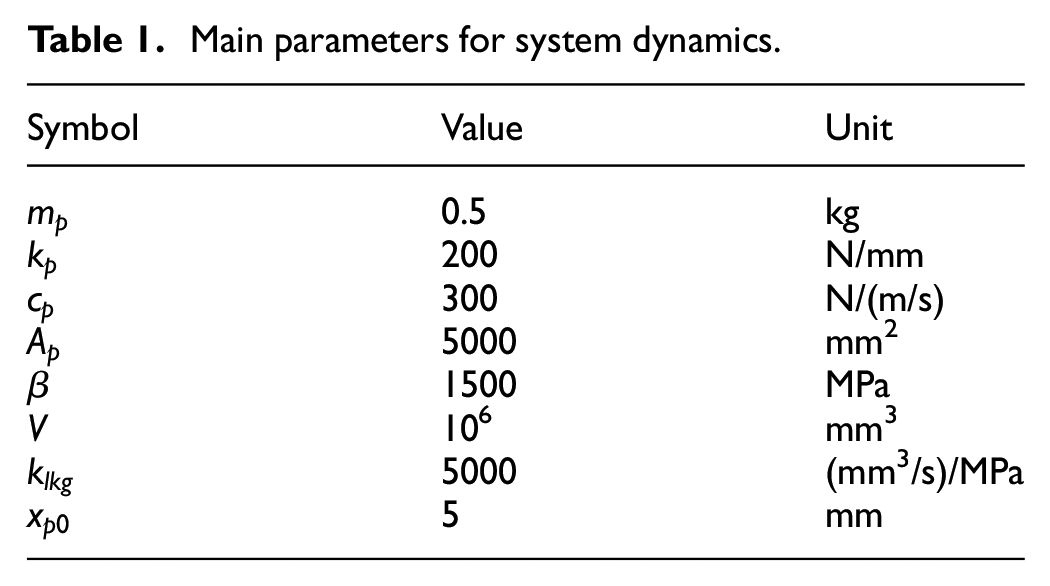
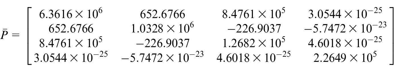
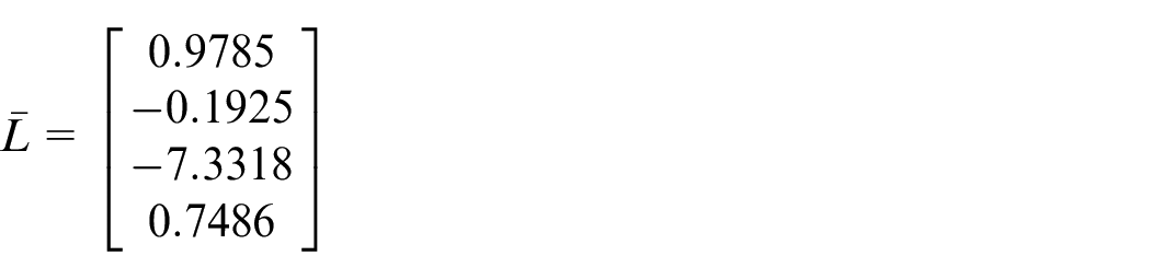
According to Table 1, the model parameters are provided as
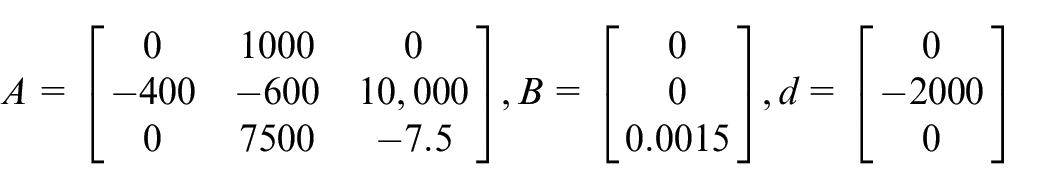
When designing the fault estimation algorithm, choosing


It is assumed that the clutch pressure sensor suffers bias fault with a magnitude of 0.02 MPa, which is expressed as
For engineering practice, the clutch pressure sensor random noise, as shown in Figure 3, is considered when estimating the sensor fault. Figure 4 illustrates the fault estimation performance when the clutch pressure sensor suffers bias fault. As shown in Figure 4, the proposed fault estimation can accurately estimate the fault magnitude of the fault without pressure sensor noise. However, sensor noise is inevitable in real working condition; the performance of the fault estimation algorithm may be affected by random sensor noise. It can be shown in Figure 5 that the estimation error is relatively low (less than 0.1% of the fault magnitude) when the clutch pressure sensor suffers from random noise. The fault estimation performance is slightly influenced by the random sensor noise.
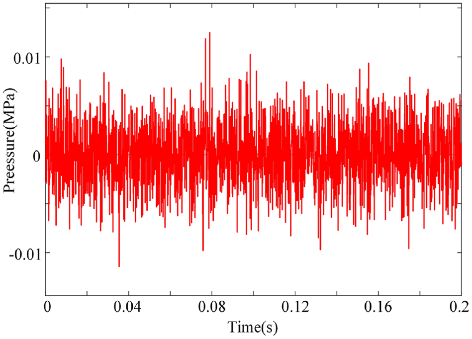
Random noise injected in the clutch pressure sensor.
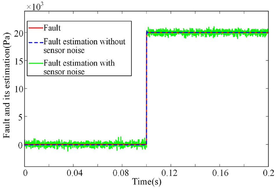
Estimation of time-invariant sensor fault.
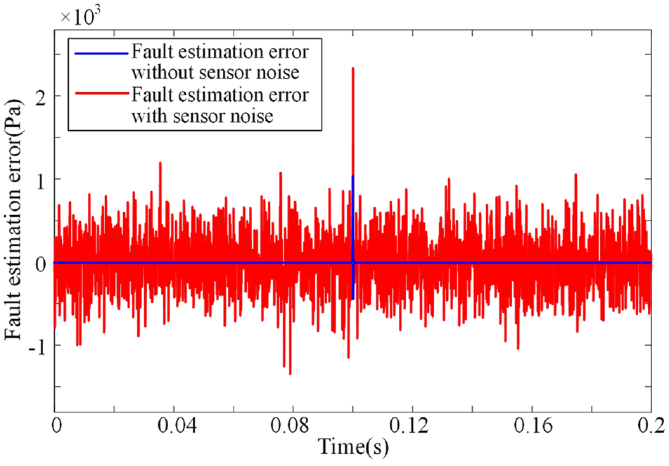
Estimation error of time-invariant sensor fault.
The time-varying clutch pressure sensor fault is

Figure 6 depicts the fault estimation result for time-varying sensor fault. It can also be seemed that the proposed sensor fault estimation algorithm has the ability to estimate the time-varying sensor fault and the sensor noise shows little influence on the fault estimation performance.
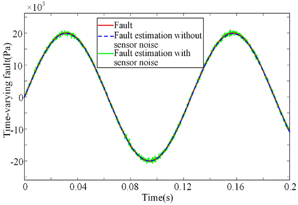
Estimation of time-varying sensor fault.
Sensor FTC analysis
Figures 7–9 show the clutch-filling performance in the fault-free case. As can be shown in Figure 7, the feedback controller performs well to track the desire reference pressure. The pressure tracking error converges to 0 quickly which is spotted in Figure 8. The clutch piston displacement is illustrated in Figure 9; it is easy to spot that the clutch piston moves to the kiss-point at 0.2 s which means that no over-filling or under-filling exists during the filling phase. Moreover, the estimated clutch piston velocity plays an important role in the feedback controller. Figure 10 depicts the estimation performance of the clutch piston velocity. The random noise, as shown in Figure 3, is also injected in the clutch pressure sensor. As shown in Figure 10, the observer equation (24) is effective to estimate the clutch piston velocity though the pressure sensor suffers from random noise.
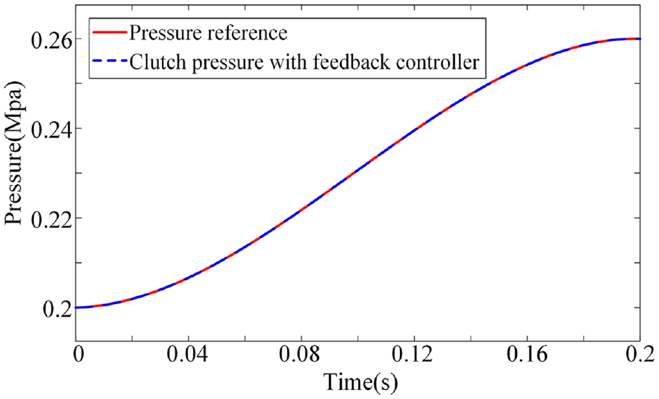
Filling pressure for the fault-free case.
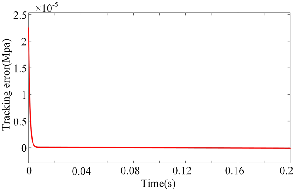
Filling pressure tracking error for the fault-free case.
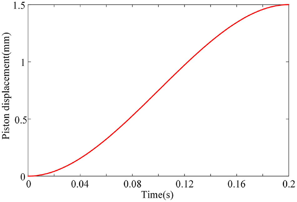
Clutch piston displacement for the fault-free case.
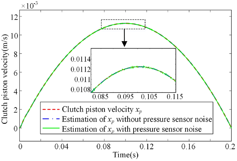
Estimation of the clutch piston velocity.
Figures 11 and 12 show the simulation results of the sensor FTC performance. As the sensor bias fault is injected into the system at 0.1 s, as shown in Figure 11, the clutch piston is unable to move to the desired displacement without sensor FTC. In contrast, with sensor FTC, the clutch filling is well achieved just like that without sensor fault. Short-to-ground is another typical sensor fault in wet clutches. Once the fault occurs, the sensor output will be zero and remains zero thereafter. Figure 12 shows the clutch-filling performance in the three different conditions. Once the sensor occurs short-to-ground fault, the current of the VFS will increase immediately, and large flow rate will be feed to the clutch chamber. The clutch piston moves to the maximum displacement immediately. This phenomenon is called over-filling. In contrast, in the sensor FTC strategy, the clutch piston will move smoothly, and the filling performance deteriorates slightly compared with the healthy condition.
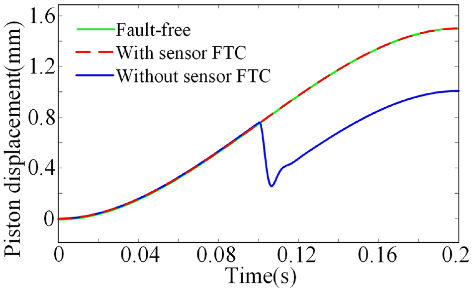
Clutch-filling performance for bias fault.
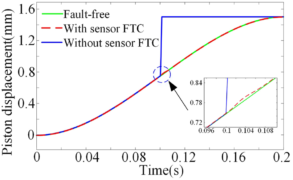
Clutch-filling performance for short-to-ground fault.
Conclusion
This article has proposed a pressure sensor FTC strategy for the filling phase of wet clutches. First, the dynamic model capturing the clutch piston dynamics and the dynamic of clutch pressure is explored. Second, the clutch-filling pressure trajectory is designed based on Pontryagin’s minimum principle. In the fault-free case, the pressure tracking controller is constructed with an observer to estimate the piston velocity. Third, an adaptive observer-based pressure sensor fault estimation algorithm is proposed. Based on the estimated fault information, the pressure sensor FTC strategy is provided. Simulation results show that the fault estimation algorithm can well capture the fault magnitude for both time-invariant and time-varying fault. In addition, it can be observed that the fault-tolerant controller can realize smooth and accurate filling of the wet clutches in the case of pressure sensor fault. Eventually, this research work provides a theoretical basis of fault-tolerant mechanism for the stable filling operation of wet clutches.
Footnotes
Declaration of conflicting interests
The author(s) declared no potential conflicts of interest with respect to the research, authorship, and/or publication of this article.
Funding
The author(s) disclosed receipt of the following financial support for the research, authorship, and/or publication of this article: The authors are very grateful to the China government by the support of this work through the National Natural Science Foundation of China (grant no. U1764259).