
Abstract
A novel rotor topology is proposed with the goal of reducing vibration in high speed rotor systems. Reduction in vibration at critical speeds is targeted. In essence, the novel topology consists of a hollow tube rotor coupled to a secondary non-rotating shaft located concentrically within the primary rotor. The two shafts are linked via a number of actively managed magnetic couplings. The topology is provided, along with an analysis comparing the out-of-balance vibration response of the proposed rotor to a comparable simple passive rotor. Designs for a test rig based on this topology are presented, together with an outline of anticipated testing and development of the idea. Special consideration is given to the design of the magnetic bearings, which form the system couplings. An internal-stator homopolar bearing design fabricated from soft magnetic composite is presented. The qualities of soft magnetic composite as a bearing core material are shown to be comparable with a standard laminated core with the added advantage of minimal eddy current losses within the primary rotor.
Introduction
In order to alter the vibration characteristics of a rotor, it is proposed to use a novel arrangement of components coupled with active control. The key principle of the concept is to include, in addition to the primary rotor, a secondary shaft which runs concentrically through the hollow primary rotor and does not rotate. The two shafts are supported independently – the primary rotor on some form of bearing (e.g. rolling element) and the secondary shaft in a clamped configuration.
Mounted along the length of the secondary shaft are one or more magnetic bearings, which are ‘inside-out’ compared to standard magnetic bearings in that the stator is on the inside and the rotor on the outside. At rotor speeds where vibration is not a problem, these magnetic bearings need not be activated, and thus there is no link between the two shafts. However, as critical rotor speeds are approached, the magnetic bearings can be activated, coupling the two shafts and changing the vibrational behaviour of the rotor.
By altering the axial position and/or number of magnetic bearings activated at any given time, the overall system characteristics can be altered, and thus a variety of frequencies of vibration are mitigated. Via active control, it is therefore anticipated that such a system will offer a powerful and flexible way to control otherwise excessive vibration.
Prior work in similar areas
A good overview of the mechanisms leading to synchronous rotor vibration is provided by Nelson. 1 Reducing vibration amplitudes theoretically permits higher speed applications, and thus smaller, higher power density machines. From a research point of view, active rotor vibration reduction techniques may be considered to split into three distinct categories.
Techniques concerned with active balancing, i.e. redistributing mass around the rotor system to remove the driving force of synchronous vibration. These methods tend to be adaptations of off-line balancing methods. Such techniques have been a topic of interest since Van de Vegte’s paper 2 proposed the design of an active balancing head. Various developments in both control logic and physical design have been presented since.3–8 A good review of this field was provided by Zhou and Shi. 9
Techniques concerned with directly applying forces to the rotor; generally this is by means of lateral forces either at the supporting bearings or mid-span along the shaft. Direct force application methods are primarily the domain of the magnetic bearing. Much work has been done on optimising the control strategies for the bearings to minimise vibration, but they are necessarily limited in their performance by constraints of physical size and load capacity. The function and application of magnetic bearings was considered comprehensively by Maslen and Schweitzer, 10 with a review paper of research topics in the field provided by Schweitzer. 11 Other types of active bearing have also been considered, including squeeze film dampers, gas bearings and laterally actuated passive bearings.12–15
In terms of applying forces at mid-span (i.e. non-bearing) locations, a significant amount of research has been done surround the concept of the active magnetic damper (AMD). An early example was provided by Nikolajsen et al., 16 who modelled a marine propulsion shaft, one of whose members rotates super-critically. By applying an AMD to this shaft, Nikolajsen demonstratesd substantial reduction of the synchronous vibration amplitude. Nikolajsen’s work was extended by Burrows and Sahinkaya 17 who developed a fast and efficient algorithm for minimising vibration in any general rotor-bearing system, which they extended to include consideration of the stability threshold associated with oil-whirl in fluid film bearings. 18 They later adapted their algorithm to include system parameter estimation, such that vibration management can be achieved without prior knowledge of system characteristics. 19 Kasarda et al. 20 proved that not only does an AMD have significant scope to reduce the amplitude of the vibration, but also that the exact placement of the AMD is not critical to its successful performance. Particular comparison was drawn between locating the AMD near mid-span (i.e. point of maximum deflection for first mode vibration), near a disk not at mid span and close to one of the supporting bearings. In a later paper, Kasarda et al. 21 focused on the potential for AMDs to be used in the control of sub-synchronous vibrations caused by external influences.
The common theme throughout all of the research presented on AMDs is that they are external-stator devices, and they are rigidly fixed to the ground/machine base. This differs from the work presented in this paper, which uses internal-stator bearings mounted on a flexible support shaft.
Techniques that are less clearly defined in nature. Methods here generally involve changing some physical property of the system (other than mass redistribution), for example stiffness or geometry, and thus alter vibration response.
The technique proposed in this paper falls somewhere between Categories 2 and 3. Here the aim is to alter the definition of the rotor system in such a way as to bypass vibration peaks, which involves an element of lateral force application to the rotor. A previous attempt at the geometry-alteration method was presented by Ortega et al., 22 where it was proposed to axially move one of the support bearings in order to change the rotor’s effective length. In contrast, this paper advocates activating additional bearings at other axial locations.
The proposed topology
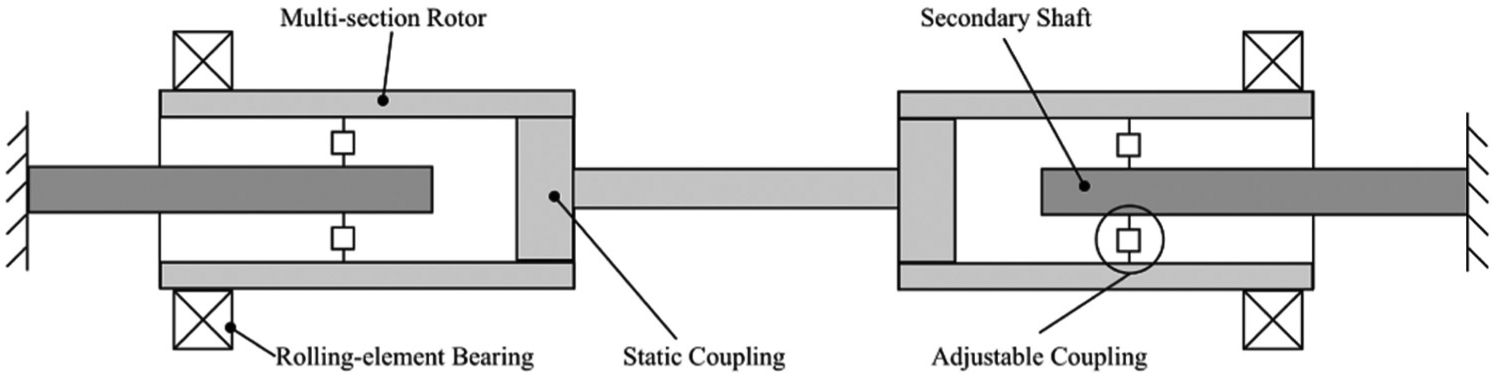
Figure 1 shows a simplified illustration of the proposed rotor layout. The rotor is a hollow tube of soft magnetic metal (e.g. ferretic steel) supported on external rolling element or other passive bearings. The secondary shaft is supported entirely separately by non-rotating supports. The material for the non-rotating shaft is chosen on the basis of its stiffness qualities, and it need not have appreciable magnetic permeability. The fact that this shaft does not rotate gives the advantage that any imbalance present in the member does not add to or complicate the dynamics of the primary rotor when the two shafts are coupled. The active couplings are achieved by internal-stator magnetic bearings. A conceptual cross-sectional view of such a device is provided in Figure 2.
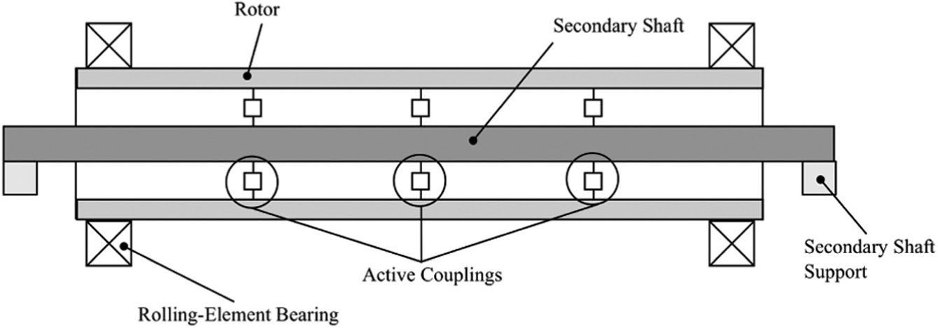
Schematic view of proposed novel rotor topology. The number and position of ‘Active Couplings’ shown is arbitrary.
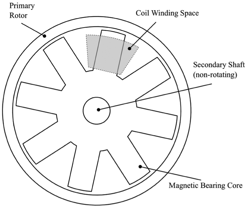
Schematic cross-section of internal magnetic bearing.
Rotor dynamics
In order to assess the effectiveness of the proposed topology in reducing rotor vibration magnitude, it has been modelled numerically using finite element methods. Details of the analysis together with a specific case study are presented.
4.1 Finite element model
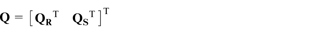
The following derivation is based on standard finite element rotor modelling, described by Nelson and McVaugh. 23 The basic unit of the finite element model used is an eight degree-of-freedom rotor section with degrees-of-freedom collected into a single vector

where

Here
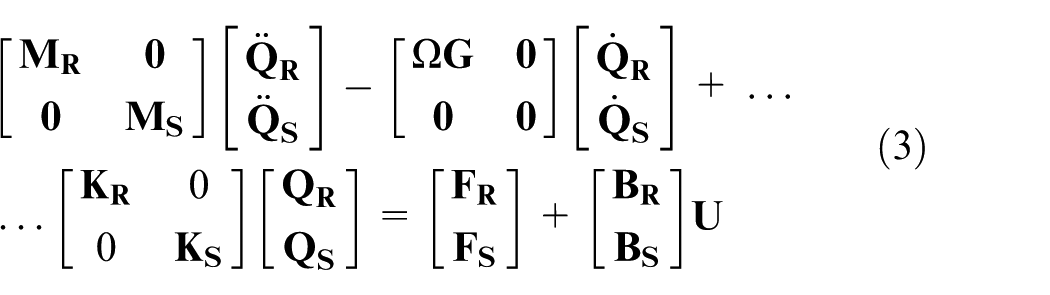
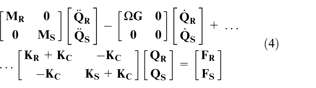
The complete equation of motion for a multi-element rotor is

where
This is standard analysis in rotor dynamics. From this point, modelling of the coupled shaft system is undertaken as follows. Firstly, the
Using this definition, an expanded form of equation (2) is presented, which demonstrates where coupling terms are applied between the two shafts:
where
The
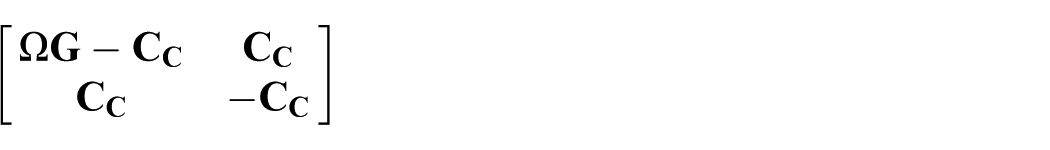
where
To achieve a frequency analysis of a rotor subject to any given forcing, one can take the Laplace transform of equation (4), set

It can be seen that for a specific rotor with a specific out-of-balance mass, all the terms on the right-hand side of equation (5) are known, and thus the response in the various degrees of freedom may be calculated.
4.2 Conceptual application
The application of this model to a particular system is now presented to illustrate the effectiveness of the internal shaft/magnetic bearing system. The rotor modelled is topologically as shown in Figure 1, with the difference that just a single magnetic bearing at the axial mid-point is used. The rotor is modelled as a 1 m long steel tube, of outside diameter 80 mm and wall thickness 4 mm. It is noted that for thin walled tubes such as the one considered here, the exact wall thickness has little effect on the shaft natural frequencies, this value being dominated by the diameter of the tube and the stiffness/mass ratio.
The non-rotating shaft used in the model is a 1.3 m long solid aluminium bar with a diameter of 20 mm. The supports for both rotor and secondary shaft are modelled as pin joints with very high stiffness and no damping.
As this case study is purely a proof-of-concept model, detailed design consideration of the magnetic bearing is omitted. It is taken that a maximum stiffness of 1 × 10⁶ N/m may be achieved. No bearing damping is applied in this case study, because while damping will reduce the amplitude of the vibration peaks, the key task is to actually shift peaks in the coupled system response when compared to the simple rotor response. This is done via bearing stiffness alone.
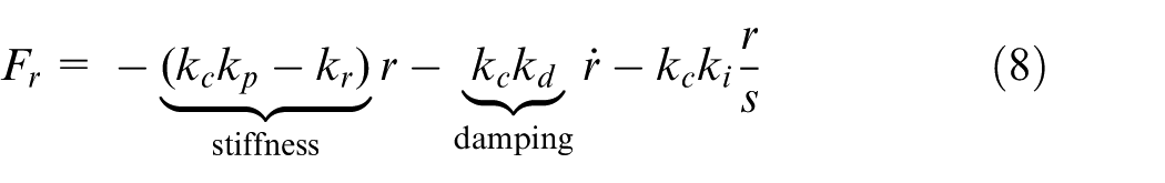
Practically, bearing stiffness and damping may be considered in the following way. For a linearised system with a bias current, the force in one axis involving a pair of opposed poles may be expressed as

where
If this is operated under proportional-integral-derivative (PID) control, such that
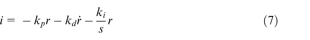
then
A frequency response was calculated for this rotor with an out-of-balance mass located at a point 40 cm from one end of the rotor. This axial location was chosen as it allows the unbalance to excite both first and second fundamental vibration modes of the rotor. A unit unbalance of 1 g cm is used to generate the results presented in this paper.
For the first simulation, the rotor was entirely decoupled from the secondary shaft (magnetic bearing switched off). The simulation was then repeated with the magnetic bearing activated and thus the two shafts coupled. Figure 3 shows both frequency responses. Note that the frequency response amplitudes are root-mean-square (RMS) averages of the responses at all nodes. It is observed that the plot of the response of the uncoupled rotor includes two critical speeds at around 220 Hz and 850 Hz. These can easily be verified analytically for a pinned–pinned beam.
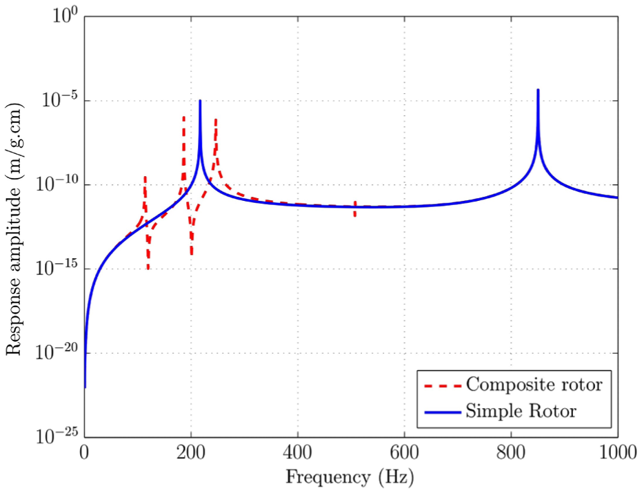
Synchronous response to out-of-balance mass on both simple and composite systems (coupling at mid-span). Amplitudes are RMS values over rotor length.
It is clear that the peak at ≃220 Hz in the simple rotor response is absent in the coupled system response. Thus if the magnetic bearing is activated at, say 200 Hz, and then deactivated at around 240 Hz, that entire vibration peak is avoided.
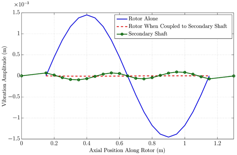
It is of interest to examine exactly what vibrations, in the sense of mode shapes and amplitudes, are present in the system at key frequencies. For instance, if the magnetic bearing is activated at 200 Hz to circumvent the rotor’s first critical speed as suggested by Figure 3, the response seen in Figure 4 is obtained. The amplitude of the rotor’s vibration is of comparable magnitude both before and after bearing activation, and it remains in a classic ‘first-mode’ shape in both conditions. This agrees with this frequency being approximately the intersection of the two vibration responses shown in Figure 3. It is observed that the secondary shaft takes a deflected form dominated by a ‘textbook’ third-mode shape. The shaft’s first four natural frequencies, taking into account the magnetic bearing with an approximate mass of 0.7 kg, are 16 Hz, 94 Hz, 171 Hz and 369 Hz. Of course, the shaft is prevented from exhibiting any even-numbered mode vibration shapes by the fact that the excitation is applied at the centre – a node in all even numbered mode shapes.
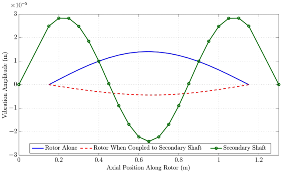
Response shapes at
At the first critical speed of the uncoupled rotor, 220 Hz, the response shape diagram in Figure 5 reinforces just how much of an effect coupling to the second shaft has in terms of amplitude reduction. It can be seen that the secondary shaft is still vibrating predominantly with a third mode shape, owing to the proximity of the excitation frequency to the third natural frequency of the shaft.
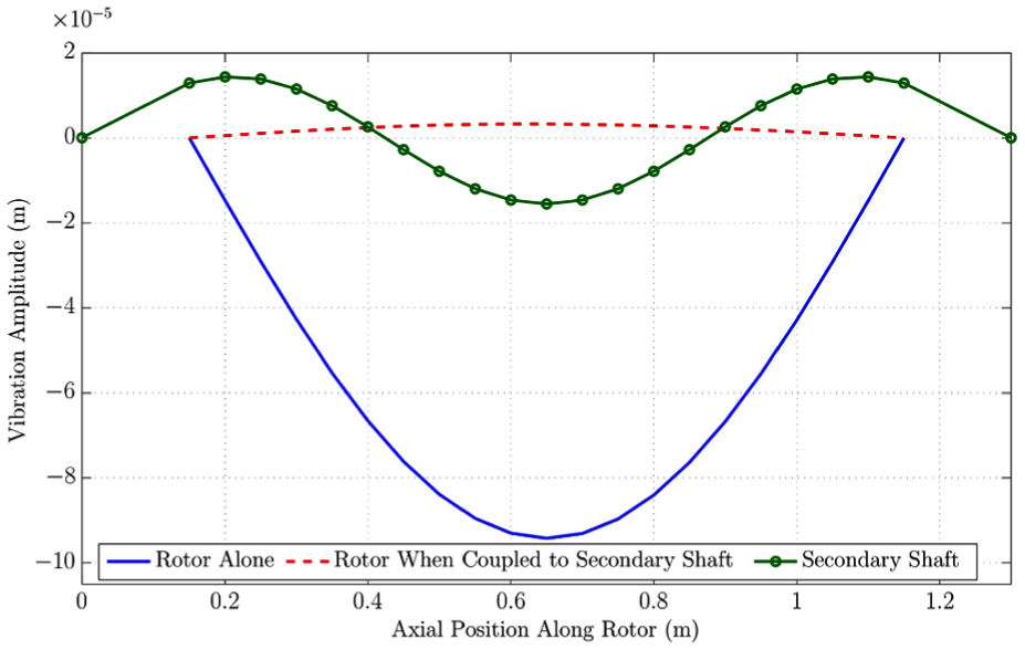
Response shapes at
The rotor arrangement for which Figure 3 shows the vibration response does not offer any avoidance of the second critical speed (≃850 Hz) as it does for the first. This is expected given that the mode shape of the second natural frequency of the rotor will have a node at central span, and thus a coupling located here is of no consequence. This is the reason for proposing either multiple or mobile (or both) magnetic couplings. Figure 6 shows the frequency response of the same rotor, but this time with magnetic bearings activated near the ¾ and ¾ axial points rather than the centre. This arrangement allows for successful avoidance of the second resonant peak in the simple rotor response. A mode shape plot is provided for the system at 850 Hz in Figure 7. It is seen that the second modal response of the rotor is greatly decreased in amplitude by the coupling. Note that the slight asymmetry observable in the mode shape plots can be attributed to the fact that the out-of-balance mass being simulated is applied to an off-centre node in the finite element model, to allow symmetric mode shape responses to be observed.
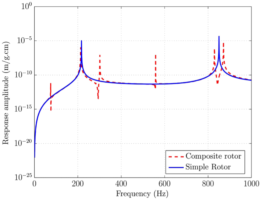
Synchronous response to out-of-balance mass on both simple and composite rotors (coupling at ¾ and ¾ axial points). Amplitudes are RMS values over rotor length.
Modal responses to an unbalance of 1 g cm at a point 40 cm along the rotor’s length at
4.3 Motion of inner shaft
An issue arises regarding the stiffness and/or motion of the inner shaft. Namely, it is vital to ensure that no contact will occur between the rotor and the magnetic bearing. It is noted that providing the displacement of the central shaft relative to the displacement of the rotor does not cause a contact between the magnetic bearing and the rotor, it is permissible for this shaft to vibrate.
To address the contact concern, an out-of-balance mass is simulated on the rotor (once again 1 g at 1 cm radius is used at a slightly off-centre node) and the amplitude of the displacement of the magnetic bearing relative to the corresponding adjacent location of the rotor is plotted. As a completely undamped system will in theory have infinite vibration amplitudes at resonances, a very small nominal value of damping is added to the magnetic bearing behaviour to ensure finite peaks.
When considering the resultant plot shown in Figure 8, it is assumed that an 0.5 mm gap between the active magnetic bearing (AMB) and the rotor is present, and also the magnetic bearing is only to be engaged at certain frequencies. Specifically, the magnetic bearing is only to be switched on at frequencies where the amplitude of rotor vibration needs to be reduced. For the rotor model referred to in this paper, with a magnetic bearing located at mid span, avoiding excessive vibration at the first critical speed requires engaging the magnetic bearing between around 190 and 230 Hz. The corresponding speed range on Figure 8 is highlighted. It can then be observed that at no point in the range where the bearing is actually active does the relative displacement come even close to the 0.5 mm. Thus there would be no contact.
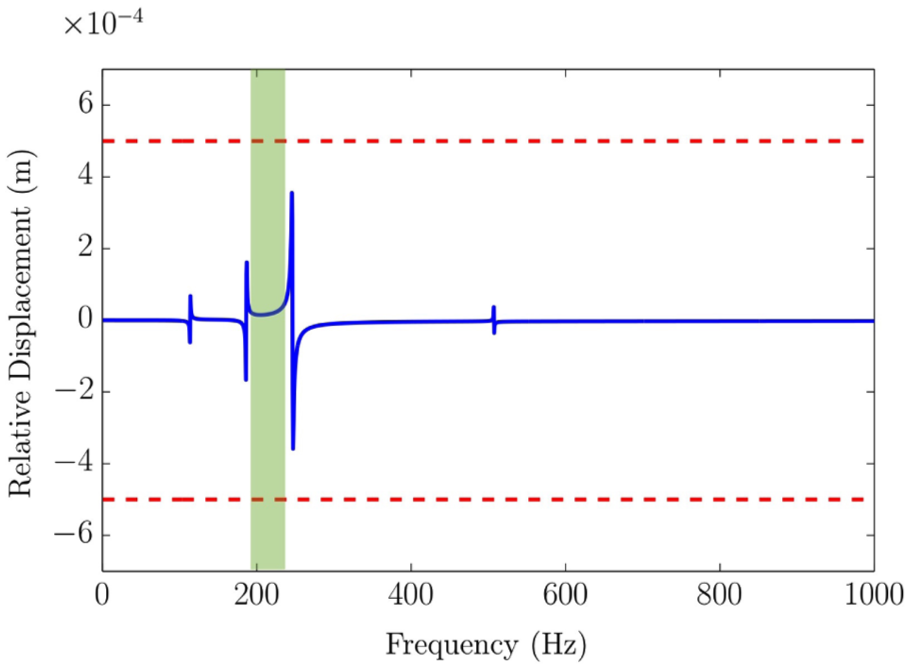
Displacement of magnetic bearing relative to corresponding location of rotor in response to an unbalance of 1 g cm at a point 40 cm along the rotor’s length at various frequencies.
Practical testing
A test rig has been designed to test the validity of the concept presented. Schematic overviews are provided in Figures 9 and 10. The rotor of the rig has been specially designed to allow supercritical rotation at relatively low speeds by building the rotor out of several sections, including a comparatively flexible middle section. Before any rotor dynamic testing is envisaged, appropriate magnetic bearings are required.
Schematic of novel rotor test rig.
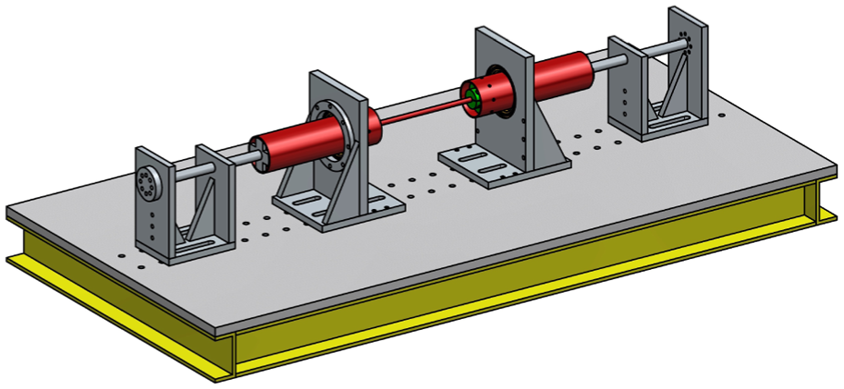
Overview of proposed rotor test rig.
Magnetic bearing considerations
In addition to the new ideas regarding rotor topology presented here, significant consideration is given to the magnetic bearings that are to form the active coupling elements. In the vast majority of magnetic bearing systems used today, the stator of the bearing is outside of the rotor. This arrangement is chosen because it removes size constraints from the design of the stator allowing higher capacity bearings to be designed. It is clearly also infeasible to use internal stator bearings on either solid shafts or very thin shafts. However, the external stator does have disadvantages. It takes up significant space along the rotor’s length that may otherwise be used for mounting other components. Furthermore, in certain applications there may not be space in the vicinity of the shaft to use an external stator bearing. The design presented here uses custom designed internal stator magnetic bearings.
A fundamental choice exists when designing a magnetic bearing between a heteropolar or a homopolar layout. By far the most common choice is the heteropolar. The chief advantage of this design is the simplicity of construction from laminations. The disadvantage is that a heteropolar bearing will tend to induce substantially greater losses in the rotor, due to the high frequency changing magnetic field the rotor experiences, building up eddy currents. Kasarda et al. 24 have presented work illustrating these differences. This issue is traditionally mitigated by fitting a laminated collar on the rotor.
In this project however, internal stator bearings are envisaged. This leads to a complication in terms of space limitation. For a given diameter of rotor, there is only a certain space available within it to fit the magnetic bearing. If part of this space is taken up with an internal laminated collar, there is then less space for the bearing, which leads to a lower force capacity bearing.
For this reason, the proposal is to use a homopolar bearing design. With homopolar bearings, the rotor experiences far less variance in magnetic field, and thus eddy currents are reduced significantly. This eliminates the need for a laminated collar. This choice does, however, have implications in terms of the material choice for the bearing core.
6.1 Stator core material
It is almost universal practice in magnetic bearing design to construct the cores out of laminated electrical steel. This provides a high level of magnetic permeability and good saturation strength, while reducing energy losses due to eddy current build up. However, design geometry possibilities are considerably limited when working with laminated steel. In particular, to facilitate manufacture it is desirable for the design to be prismatic in the stacking direction. It is well documented that this requirement makes the manufacture of homopolar magnetic bearings more complex and costly than heteropolar designs.
To overcome this trade off, it is proposed that laminated steel is replaced with a powder metal based soft magnetic composite (SMC) as the core material for a magnetic bearing. At present, the use of SMC material in magnetic bearings is very limited, for example, external stator magnetic bearings incorporating SMC cores have been considered by Fleischer and Hofmann.25,26 In this paper, SMC is considered for the core for the internal stator homopolar magnetic bearing design. SMC offers some clear advantages over laminated steel.
It has effectively isotropic lamination and is thus capable of supporting alternating magnetic flux in any direction without significant eddy current build up.
It has the ability to be formed into complex 3D shapes.
The adoption of an SMC allows the magnetic bearings to use a compact, single piece homopolar design similar to that shown in Figure 11. A photograph of a completed bearing to this design is shown in Figure 12. Fabricating this design directly from laminated steel in an analogous way to heteropolar bearings would incur greater eddy current losses than an SMC core as not all directions are insulated in the steel. This can be seen in Figure 13. The lamination in the shaded area marked ‘A’ is in the correct orientation to retard the formation of eddy currents, whereas in the perpendicular field highlighted in area ‘B’, the laminations are not oriented in the optimum direction.
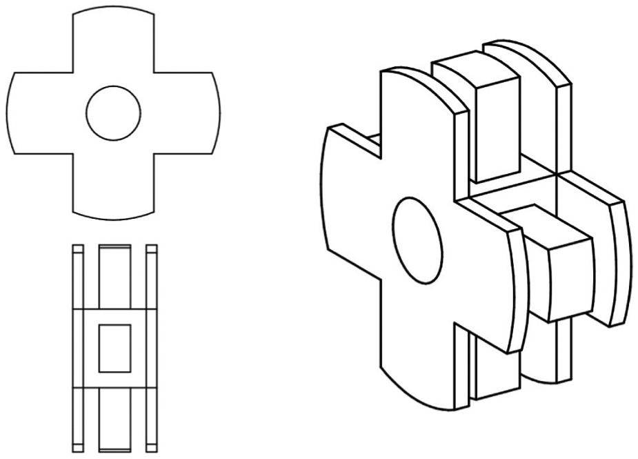
An internal-stator homopolar bearing core design.
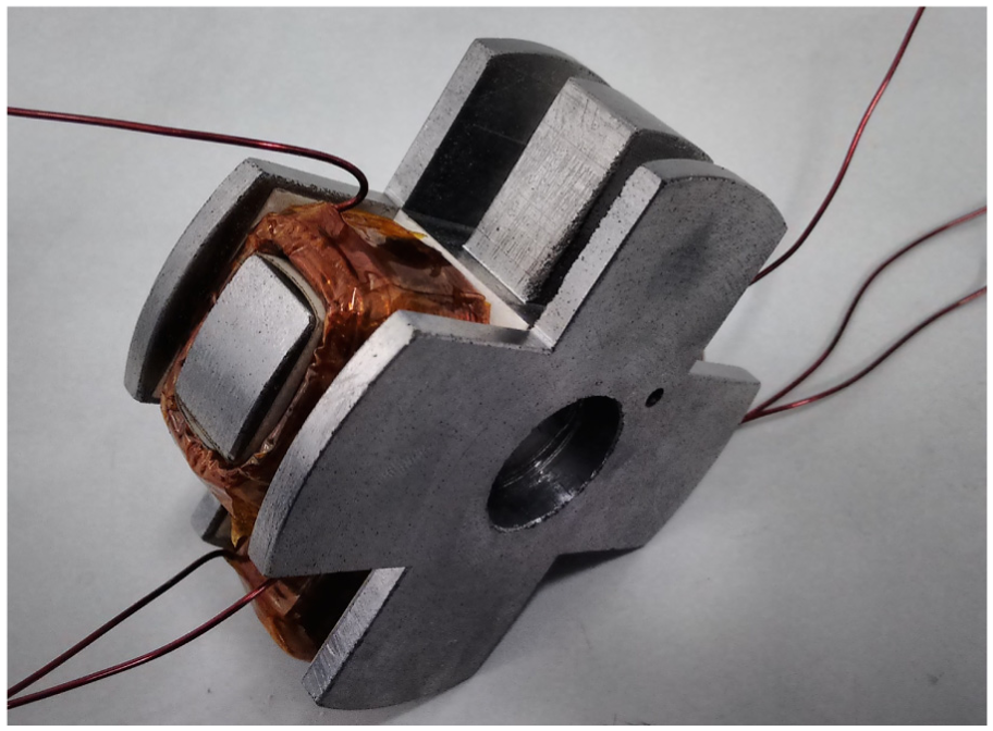
An SMC homopolar magnetic bearing. This geometry would be very difficult to fabricate with laminated steel sheets. Note that one coil is removed for illustration purposes.
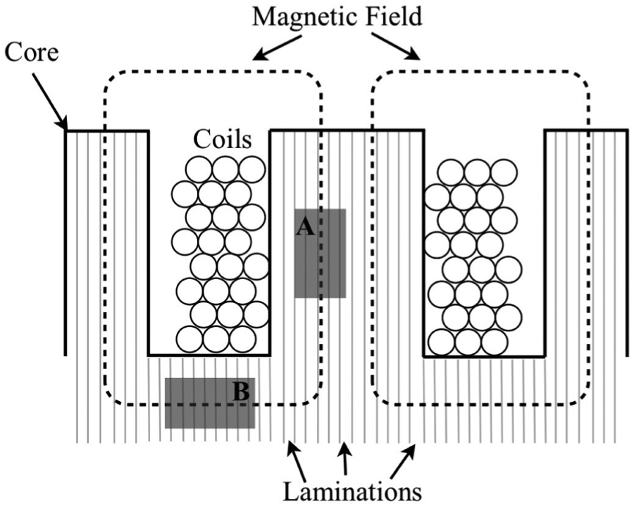
In a homopolar bearing, uniform laminations cannot optimally block eddy current formation in all directions.
In general, the SMC is fabricated from iron powder, chemically treated to leave each individual grain with a thin layer of electrically insulating material around the outside. The powder is then compressed in a mould to form the final shape of the component required. Post-formation heat treatments are also applied to relieve stress from the compaction process.
Of course, the compaction-forming of powder-metal components is generally only financially viable on production scale runs. For this reason, prefabricated discs of a version of the SMC material specially treated to have good machinability properties were used. It is noteworthy that in altering the material to give good machinability, the magnetic properties of the SMC are slightly adversely affected. A microscope image of the structure of the material is shown in Figure 14.
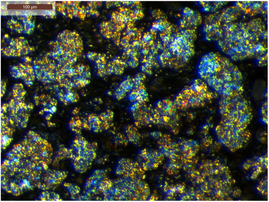
An optical microscope image showing the structure of the SMC.
There is of course still the issue of space limitation when designing an internal-stator magnetic bearing. In general this means one is limited by the load capacity of the bearing. This is, however, by no means a prohibitive difficulty in this design, owing to the fact that the bearings are not required to support the mass of the rotor, which is dealt with by external rolling element bearings.
6.2 SMC performance
In using a new material for the bearing core, it is naturally important to examine its performance against the traditional material used in the application, in this case laminated steel. Two performance criteria in particular are of interest to the majority of magnetic bearing designers, and those are force capability and thermal characteristics. To facilitate testing of these properties, two magnetic bearings were fabricated of identical geometry, but with differing core materials. One uses 0.3 mm steel laminations, while the other uses an SMC. Note that these bearings are distinct from the bearings to be used on the main rotor test rig. These bearings are of internal-stator, heteropolar design, owing to the difficulty already described in manufacturing a compact homopolar bearing from laminations, and are shown in Figure 15. The heteropolar option is a valid choice for comparison between the SMC/laminated steel core variants since the tests were undertaken under zero speed rotor conditions, which eliminates rotational bias between heteropolar/homopolar designs. Clearly the homopolar option would be selected for the rotor test facility to avoid speed induced eddy currents in the rotor steel.
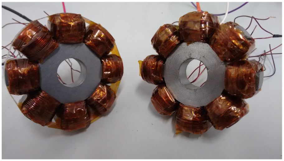
Two internal-stator heteropolar bearings for comparison between laminated steel (left) and SMC (right) cores.
A test rig was constructed to allow the measurement of the forces exerted by a pole pair of these bearings over various frequencies of coil excitation. It allows for the rigid mounting of a magnetic bearing directly above a load cell. The top of the load cell carries a curved block of SMC to receive the magnetic field. The arrangement can be seen in Figure 16. The coils of the bearing are powered by a digital amplifier, which is fed by a computer generated demand.
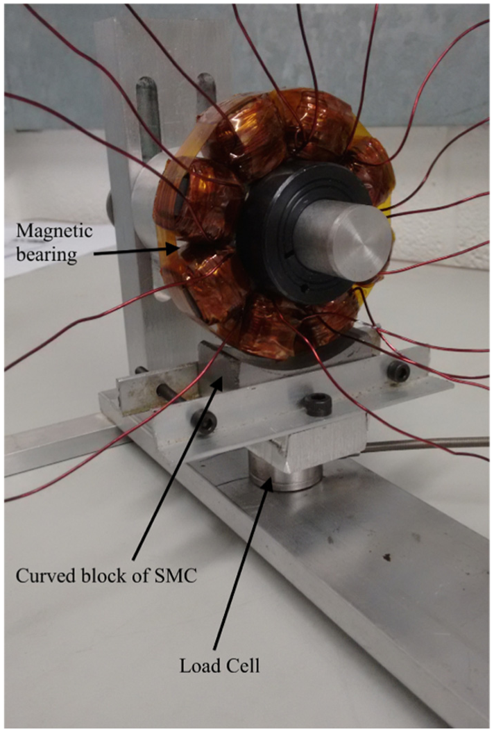
Load cell rig for testing magnetic bearing force capacity.
Tests were performed by feeding the coils with a fixed amplitude chirp signal, varying in frequency from 100 to 1500 Hz. Note that the current is offset to always be of positive magnitude, with a peak amplitude of 5 A, as in

This is to avoid the circumstance when a non-offset current is used which would lead to the force frequency seen by the load cell being twice the current frequency.
The results of this testing are seen in Figure 17. The force characteristics are very similar between the two bearings. Note that the peak in the force measurement seen at around 400 Hz is due to internal load cell dynamics, rather than an effect of the bearing itself. Hence the force measured is that transmitted to the base.
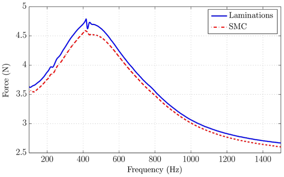
Force test data comparing traditional laminated core with SMC core.
The power losses from magnetic bearing stators also manifest themselves through heat generation. Therefore excess losses not only reduce system efficiency, but also have the potential to cause thermal damage, particularly to insulating coatings on the copper wires and on sheet/grain laminations. Thus it is of interest to ensure that an SMC core does not incur greater thermal losses than a laminated one, which may be considered the benchmark.
In theory, there should be lower losses in an SMC core, as there should be less eddy current build up. In order to assess the core thermal characteristics, a test was performed whereby a single pole pair of each bearing was fed a 6A (peak) AC current at 1000 Hz. The temperature of the cores was recorded over time with a digital thermometer. A heat transfer compound paste was used to couple the bearing core to the probe of the thermometer for accurate results. The results from the two different core materials are shown in Figure 18. The results show very similar thermal characteristics between laminated and SMC core materials, with temperature rise being attributed to heating in the copper coils, rather than core effects.
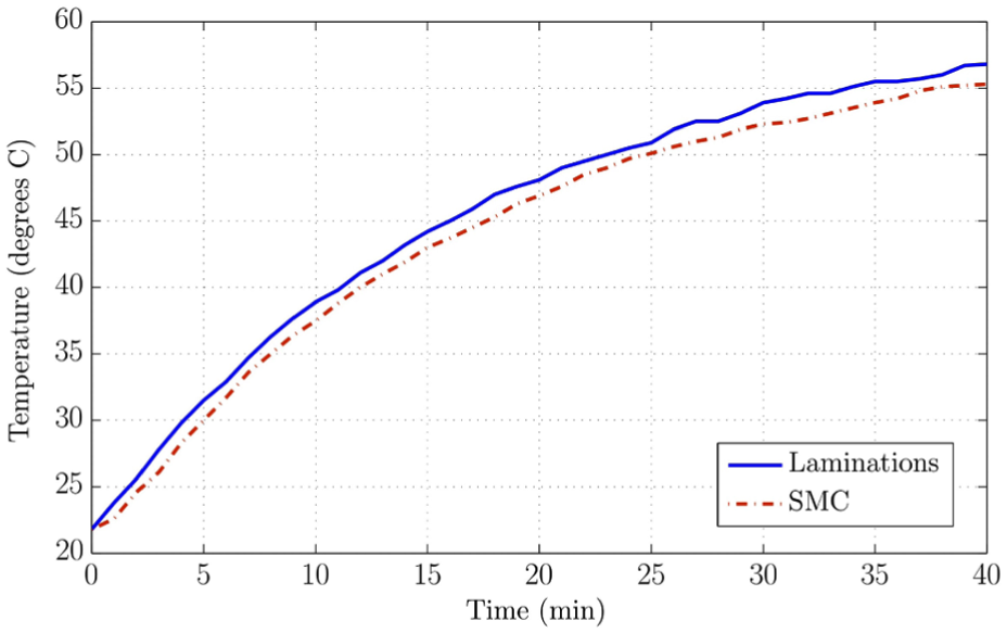
Core heating characteristics.
These results on the performance of the SMC as a magnetic bearing core material confirm that an SMC offers equal performance to the laminated version, with the considerable advantage of increased design possibilities resulting from its isotropically ‘laminated’ quality.
Conclusions
A novel layout of coupling a rotor to a secondary shaft by way of internal-stator active magnetic bearings has been proposed. Finite element modelling of rotor unbalance responses illustrates that it is possible to design a system whereby the critical speeds of the primary rotor are substantially altered by coupling it to a secondary shaft. Therefore by actively engaging and disengaging the magnetic couplings, it is possible to avoid excessive vibration associated with the rotor’s critical speeds. Design considerations relating to internal-stator magnetic bearings are presented, with a focus on core material choice between laminations and powder metal based SMC. SMC cores are shown to exhibit marginally lower force capacity than laminations, but also a slightly lower temperature rise under alternating current operation. Importantly though, SMC opens the possibility for efficient and easy to manufacture internal-stator homopolar bearing designs, which do not require internal shaft laminations due to the minimal eddy current build up in the rotor. In terms of both thermal managements and practicality, this makes SMC the material of choice for the new rotor topology presented.
Footnotes
Appendix
Acknowledgements
The authors are grateful to the James Dyson Foundation for its support of this research.
Declaration of conflicting interests
The author(s) declared no potential conflicts of interest with respect to the research, authorship, and/or publication of this article.
Funding
The author(s) received no financial support for the research, authorship, and/or publication of this article.