
Abstract
This research presents a Techno-Economic-Environmental (3E) evaluation of a cascade phase change material (PCM)-based thermal energy storage (TES) integrated into a solar-driven cooling system designed to meet different cooling loads, including freezing, refrigeration, and air-conditioning. The system employs paraffin and salt hydrate PCMs with modified melting points to enable multi-temperature operation through thermal stratification. The configuration combines ammonia-based charging and R134a/water discharging loops, supported by TRNSYS–MATLAB co-simulation, to analyse the dynamic thermal response, phase transition behaviour, and overall system efficiency. Results show that the cascade PCM arrangement provides stable cooling performance across diverse load ranges, with PCM2 (4°C) and PCM3 (15°C) contributing over 90 % of total stored energy. However, the high capital investment (£2.2 million) leads to an extended payback period of approximately 115 years, despite significant electricity savings and a reduction in CO2 emissions compared to conventional systems. The findings underscore the technical feasibility and environmental merit of cascade PCM-based TES while identifying cost as the main barrier to large-scale adoption. The study contributes a general 3E framework combining thermal, economic, and environmental metrics to evaluate cascade PCM–TES integration for multi-load solar cooling. The results provide design guidance and highlight future research opportunities in cost optimisation, composite PCMs, and modular TES architectures to enhance both affordability and scalability.
Keywords
Introduction
Latent heat storage with phase change materials (PCMs) is among the most efficient methods for storing thermal energy. Consequently, PCMs are used to enhance the thermal storage capacity of a variety of systems.
1
The use of phase change materials (PCM) improves heat storage capacity and offers better isothermal performance during both charging and discharging, compared to sensible heat storage. Additionally, thermal energy storage (TES) systems used for heating and cooling are essential for the efficient functioning of many industrial processes.
2
Desirable characteristics of any storage system include high energy storage density and significant power capacity for both charging and discharging.
3
These storage solutions have been extensively studied over time to address various issues related to the materials used, such as low thermal conductivity and the separation of the PCM.
4
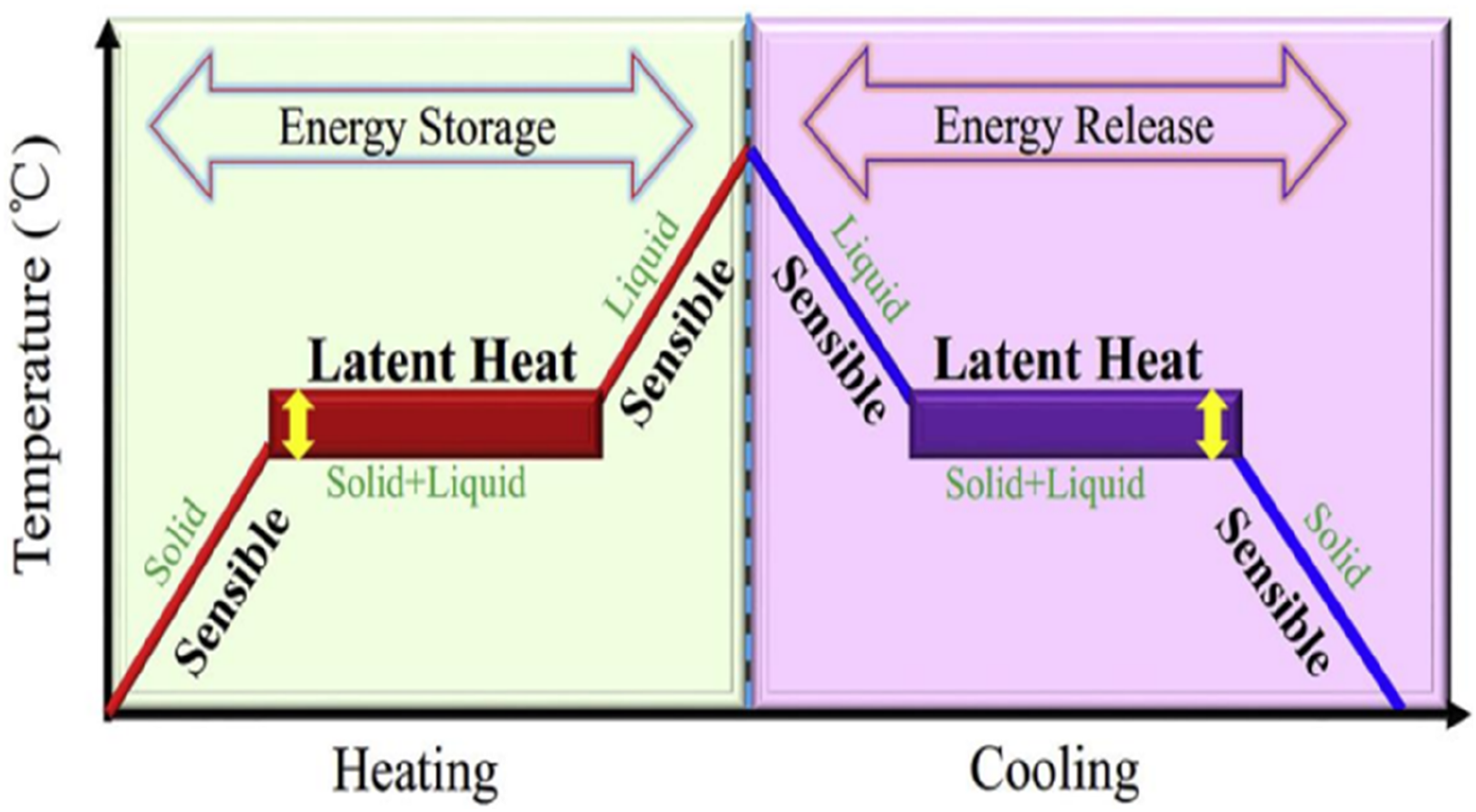
Phase Change Materials (PCMs) function by absorbing and releasing thermal energy during their phase transition processes, especially during melting and solidification. As the ambient temperature rises, a phase change material absorbs thermal energy until it reaches its specific melting point. The phase change material shifts from a solid state to a liquid state, absorbing a significant amount of latent heat without a noticeable increase in temperature. This thermal absorption process allows PCMs to serve as thermal reservoirs, maintaining a stable temperature even as ambient conditions become warmer (Figure 1). This property makes them particularly effective in situations that require precise thermal management.
5
Solid-liquid PCMs function based on their working principle (Mandal, 2024).
5
The solid–liquid transformation mechanism of PCMs, as described by Mandal (2024), supports the latent-heat storage principle employed in this study. Mandal’s work also highlights recent stabilisation and encapsulation methods that enhance PCM reliability during cyclic thermal operation, which are directly relevant to the present cascade storage design. When implementing PCM systems, this phase-change process involves the absorption and release of a significant amount of energy, forming the basis of thermal buffering during the charging and discharging cycles. 5
Phase change materials (PCM) have diverse applications, including domestic hot water storage, space heating and cooling in buildings, peak load management, solar energy utilization, and seasonal energy storage. 6 Recent academic investigations into Phase Change Materials (PCMs) used in Thermal Energy Storage (TES) systems operating under high thermal conditions have highlighted their potential significance in enhancing energy efficiency and overall performance. 7
The incorporation of phase change materials (PCMs) into cooling systems presents a promising approach to enhancing energy efficiency and ensuring thermal comfort in various environments. PCMs are materials that can store and release significant amounts of latent heat during their phase changes, typically transitioning from solid to liquid and vice versa. This unique thermal storage property allows PCMs to absorb excess heat when the surrounding temperature rises and release stored heat when the temperature drops, thus minimising temperature fluctuations and energy consumption.
In building infrastructure, PCMs can be integrated into walls, ceilings, or ventilation systems to reduce cooling demands and stabilize indoor climates. In the fields of electronic cooling and thermal energy storage, PCMs help regulate heat generated by devices or fluctuations in external environmental conditions. Additionally, their use in HVAC systems and passive cooling strategies contributes to lowering peak energy consumption and enhancing sustainability. 8 Recent advancements in encapsulation methods, material selections, and system integration have expanded the potential applications of PCMs in both commercial and residential settings. As energy efficiency becomes an increasingly important design element in modern infrastructure, PCM-based thermal management systems rise as a practical and environmentally friendly solution. 9
Benefits of PCMs in cooling applications
Energy Efficiency: Phase Change Materials (PCMs) can significantly reduce energy consumption by capturing excess cooling energy during times of low demand and releasing it when demand peaks. 10 Thermal Stability: They ensure that temperatures remain nearly constant during phase transitions, which enhances the thermal inertia of the cooling system. 11 Passive Cooling: Integrating PCMs into building exteriors can reduce the absorption of external heat, leading to a cooling load reduction of up to 14.82%. 12
Applications of PCMs in Building Components: PCMs are used in walls and ceilings to improve thermal efficiency and reduce reliance on active cooling systems 13 Refrigeration Systems enhance the efficiency of refrigeration units, making them well-suited for personal cooling solutions and food transport. 11 Integration Techniques Macro-Encapsulation: This method is widely used to integrate PCMs into construction materials, enhancing efficient thermal management. Material Selection: Paraffin and salt hydrates are often preferred for their excellent thermal properties and effectiveness in various building applications. 13 While the incorporation of PCMs offers significant advantages, challenges like material pricing, long-term durability, and the need for further research on optimal configurations remain. Addressing these challenges is crucial for the widespread adoption of PCM technology in cooling applications.
Recent studies have further advanced PCM technology through material modification and hybrid system integration. For instance, multi-objective optimisation of thermo-electric generator–heat-sink assemblies have demonstrated significant gains in thermal transfer efficiency under both natural and forced convection conditions.14–16 Other investigations have enhanced PCM performance by including nanoparticles or using composite matrices to improve thermal conductivity and reduce super-cooling.17,18 Similarly, research on solar-heated PCMs for heavy-crude-oil flow assurance has confirmed the stability of salt-hydrate materials under cyclic thermal loading. 17 These developments illustrate a rapid evolution of PCM research from basic material enhancement toward system-level optimisation.
However, despite these advances, most published works still treat PCM units as isolated storage components, with limited attention to multi-temperature operation or integration within complete solar-assisted cooling systems. The lack of studies addressing both the material and system perspectives particularly for cascade PCM arrangements designed to meet different cooling loads creates a clear research gap that this study aims to address.
The principal novelty of this study lies in the integration of a cascade phase change material (PCM) thermal energy storage system into a single solar cooling configuration that simultaneously meets three distinct cooling demands freezing, refrigeration, and air-conditioning. Contrasting most previous works, which focus on single-stage or uniform-temperature PCM systems, the present study employs a multi-layered PCM arrangement with thermal stratification across different melting points (−4°C to 22°C). This enables efficient load matching and temperature specific energy storage within one integrated system. In addition, the work couples MATLAB-based component modelling with TRNSYS system simulation through a dynamic co-simulation link to capture real-time thermal interactions and performance. Compared to earlier research, this approach offers a 3E (Techno-Economic-Environmental) perspective, quantifying not only the thermal efficiency but also the cost and CO2 reduction potential of cascade PCM storage in multi-demand cooling applications.
Accordingly, the primary objective of this study is to design, simulate, and evaluate a cascade PCM-based thermal energy storage system integrated within a solar cooling network capable of meeting multiple cooling loads under varying operating conditions. The research aims to (i) investigate the thermal behaviour and energy storage capacity of stratified PCMs with distinct melting points, (ii) assess the system’s overall performance through TRNSYS–MATLAB co-simulation, and (iii) perform a techno-economic-environmental (3E) analysis to quantify its feasibility and sustainability. This integrated approach is necessary to bridge the current gap in literature, where most existing studies either examine single PCM configurations.
System description and modelling
Figure 2 illustrates the flow directions for charging and discharging in a cascade PCMs thermal energy storage system. During the charging phase, cold is delivered into the storage tank, while the discharging phase removes the stored heat from the tank. The storage comprises three layers, each potentially possessing unique phase change temperatures to facilitate thermal stratification and enhance energy efficiency. Charge and discharge processes directions of cascade PCMs storage.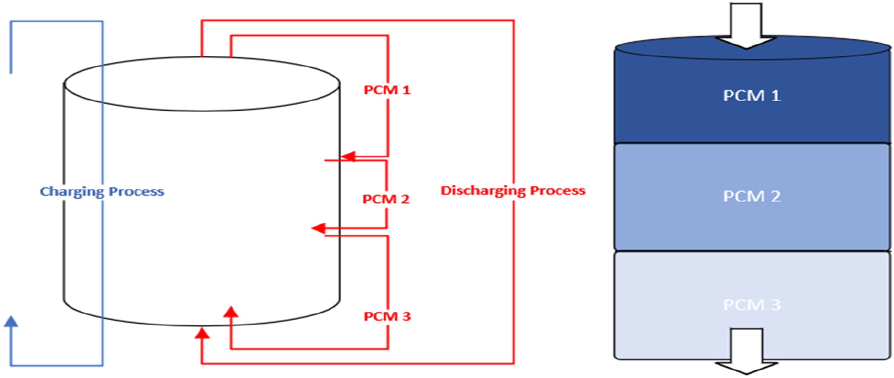
Figure 3 illustrates a cascaded thermal energy storage system that uses phase change materials (PCMs) to fulfil three distinct cooling demands: freezing (−4°C), refrigeration (4°C), and air conditioning (16°C). A central chiller cools the working fluid to 0°C, which then flows sequentially through three PCM storage units. Each unit absorbs heat and warms the fluid as it moves downward, with outlet temperatures increasing from 2°C to 10°C and finally to 24°C before returning to the chiller. At the same time, each PCM unit provides cooling to its respective demand via a separate loop, maintaining precise temperatures through latent heat storage at specific melting points. This design enhances efficiency by aligning each PCM’s thermal properties with the temperature requirements of the connected cooling load. Schematic diagram of Cascade PCMs storage linked to loads.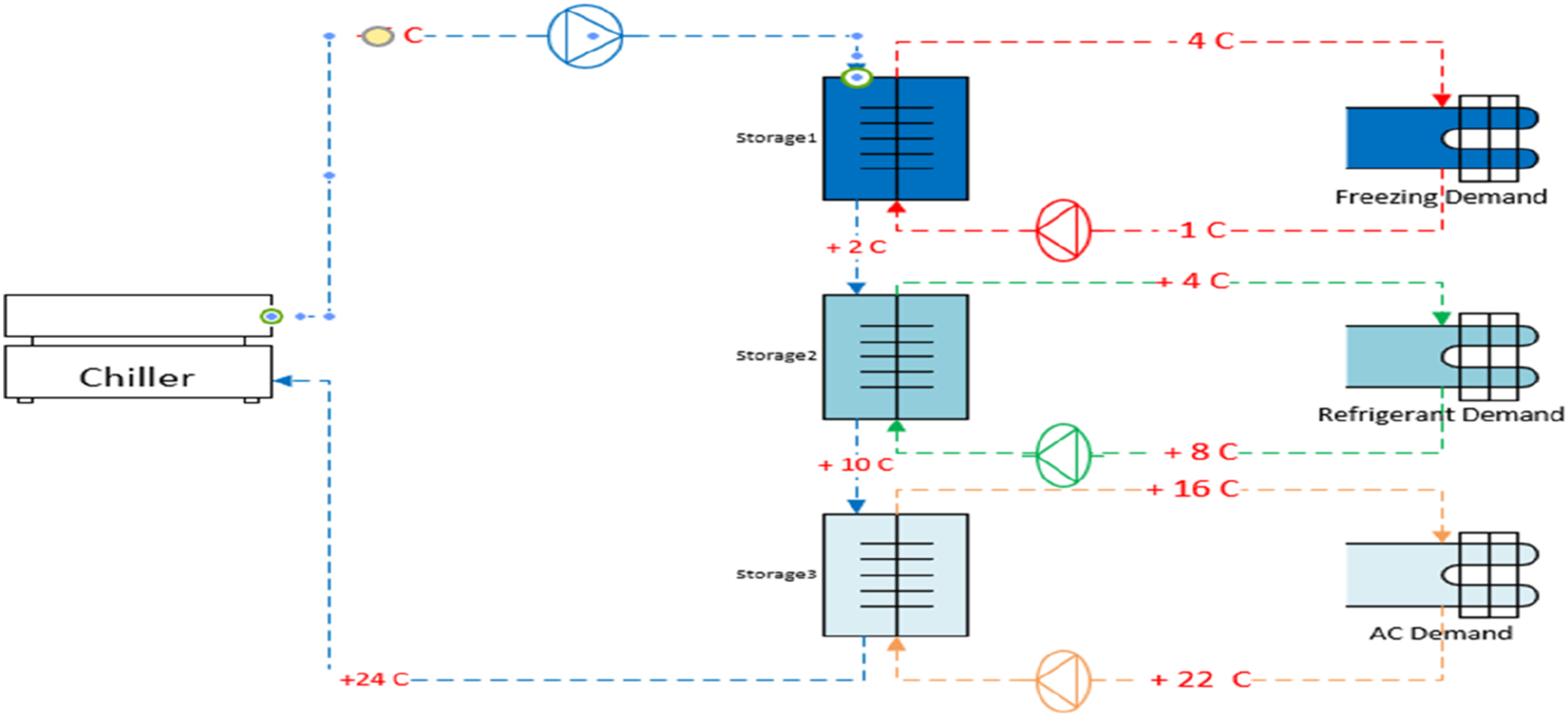
Cooling load demand required
Figure 4 illustrates the peak design heat load associated with three different phase change material (PCM) zones PCM1, PCM2, and PCM3 used in a cascade thermal energy storage system for a non-domestic building. PCM1 exhibits the lowest design load at approximately 70 kW, followed by PCM2 with a peak load of 160 kW, and PCM3 with the highest peak load of 220 kW. These values reflect the distinct thermal requirements for different temperature zones, typically corresponding to freezing, refrigeration, and air conditioning demands, respectively. The increasing trend in load highlights the need for higher thermal storage capacity in higher-temperature cooling applications. Peak cooling load requirement for various demands in a non-domestic building.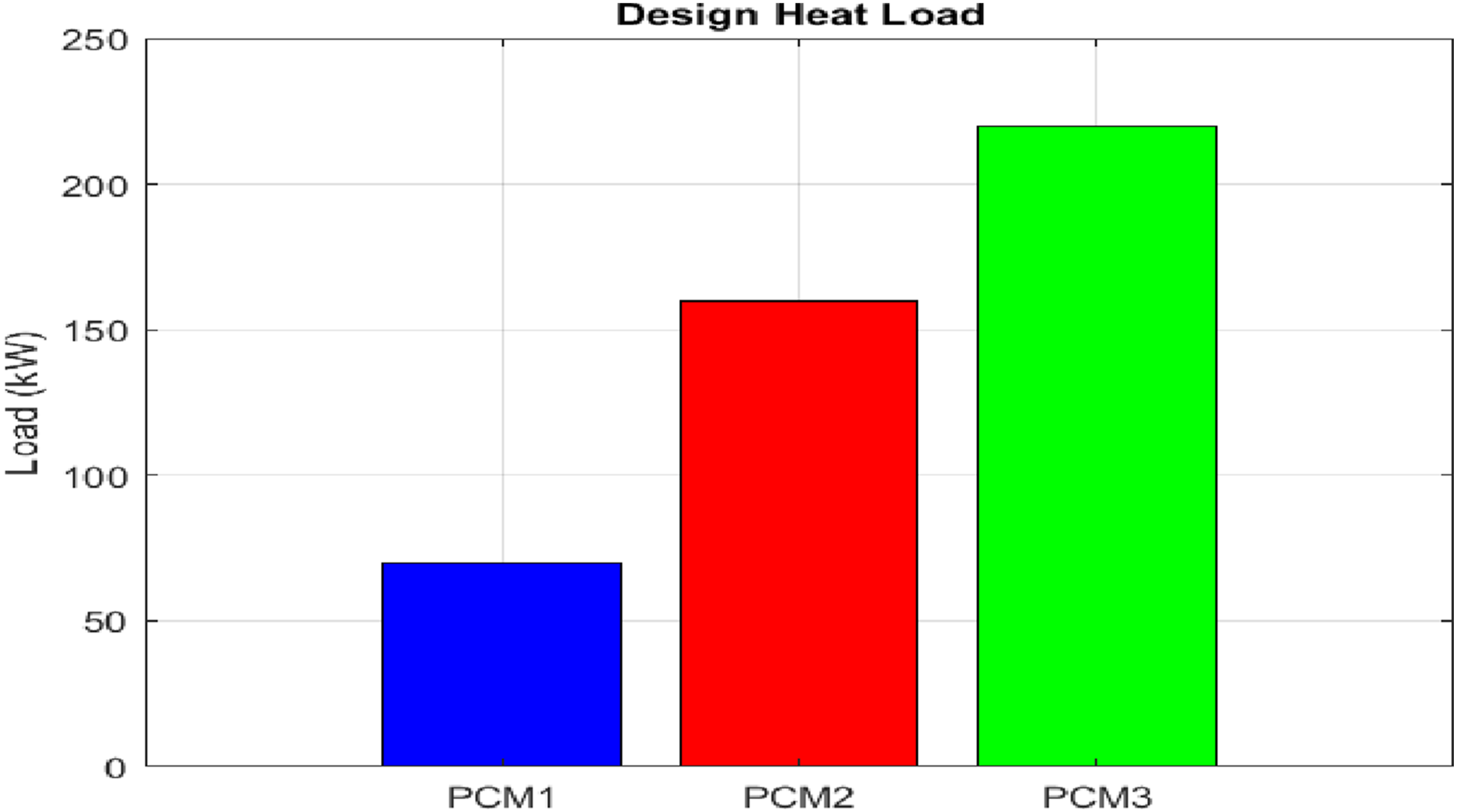
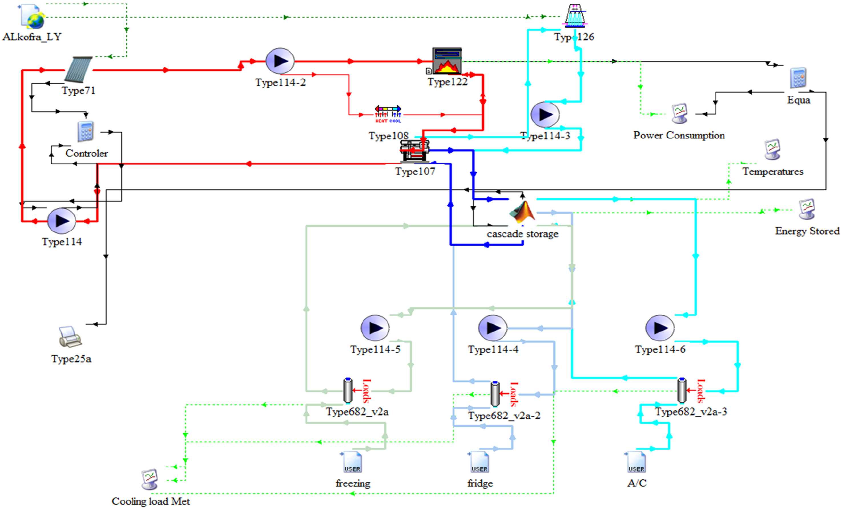
Figure 5 presents the monthly variation in energy usage across three types of cooling demand freezing, refrigeration (fridge), and the overall cooling demand—throughout the year. The energy demand follows a seasonal pattern, with the highest consumption observed during the summer months (June to August), driven by increased ambient temperatures and higher cooling requirements. Refrigeration load consistently dominates the total energy usage, peaking above 14,000 kWh in July, followed by the overall demand, and freezing, which reaches a maximum of around 4000 kWh. This profile is essential for optimizing the size and operation schedule of thermal energy storage systems, ensuring sufficient capacity is available during peak months while avoiding oversizing for lower-demand periods (Figure 6). Average cooling load requirements profile for different cooling demands per year. Solar cooling system integrated with cascade PCMs storage to meet various demands.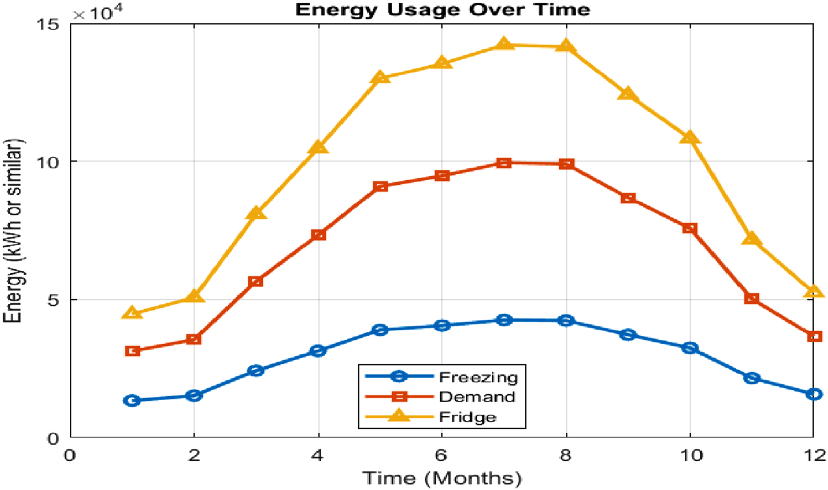
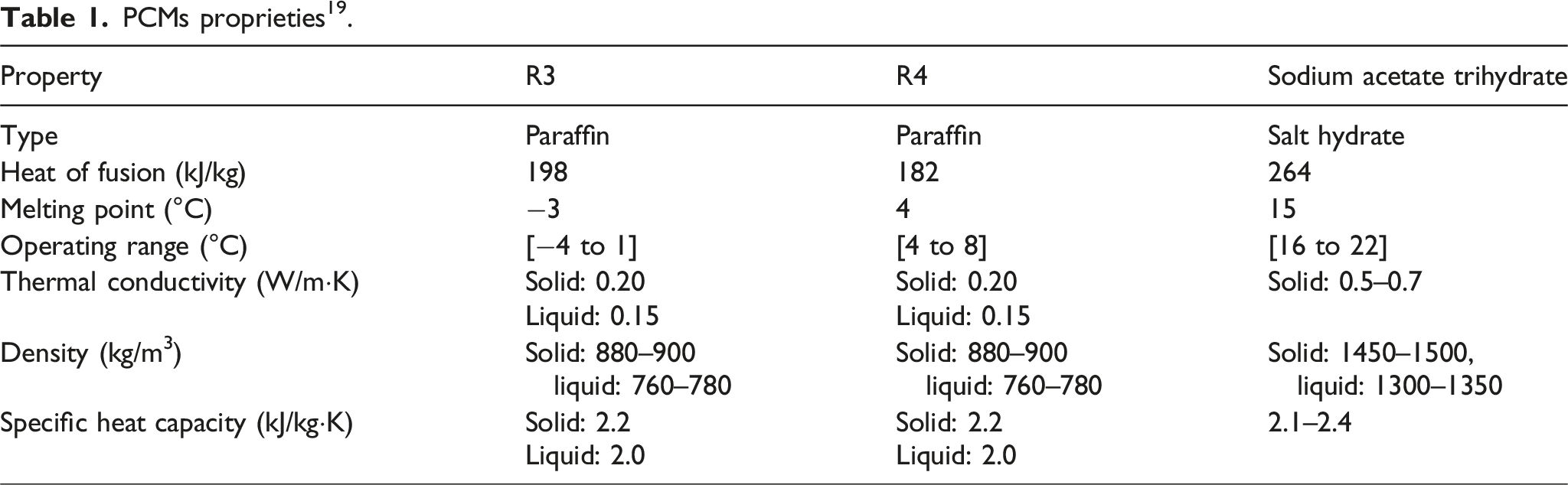
PCMs proprieties 19 .
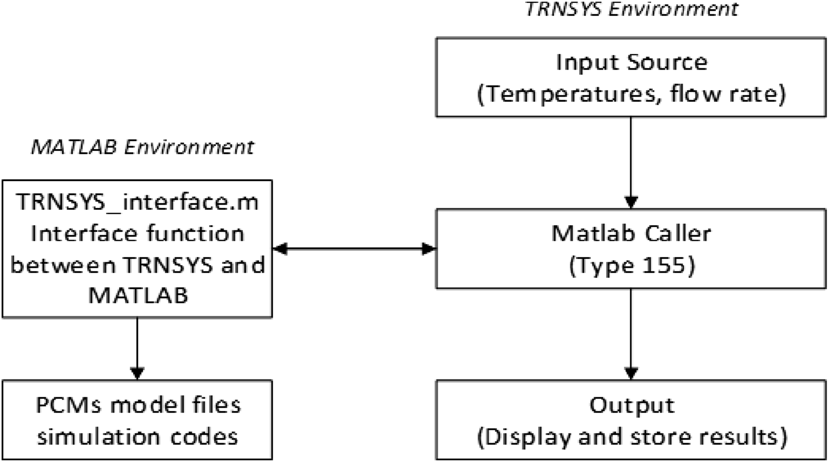
Flow chart illustrating the TRNSYS–MATLAB co-simulation process for the cascade PCM thermal energy storage (TES) analysis. The TRNSYS environment provides input variables (temperatures, flow rate) to MATLAB through the Type 155 interface. MATLAB executes the PCM model files and returns calculated energy balance, heat-exchange, and temperature data to TRNSYS, where system-level performance results are displayed and stored.
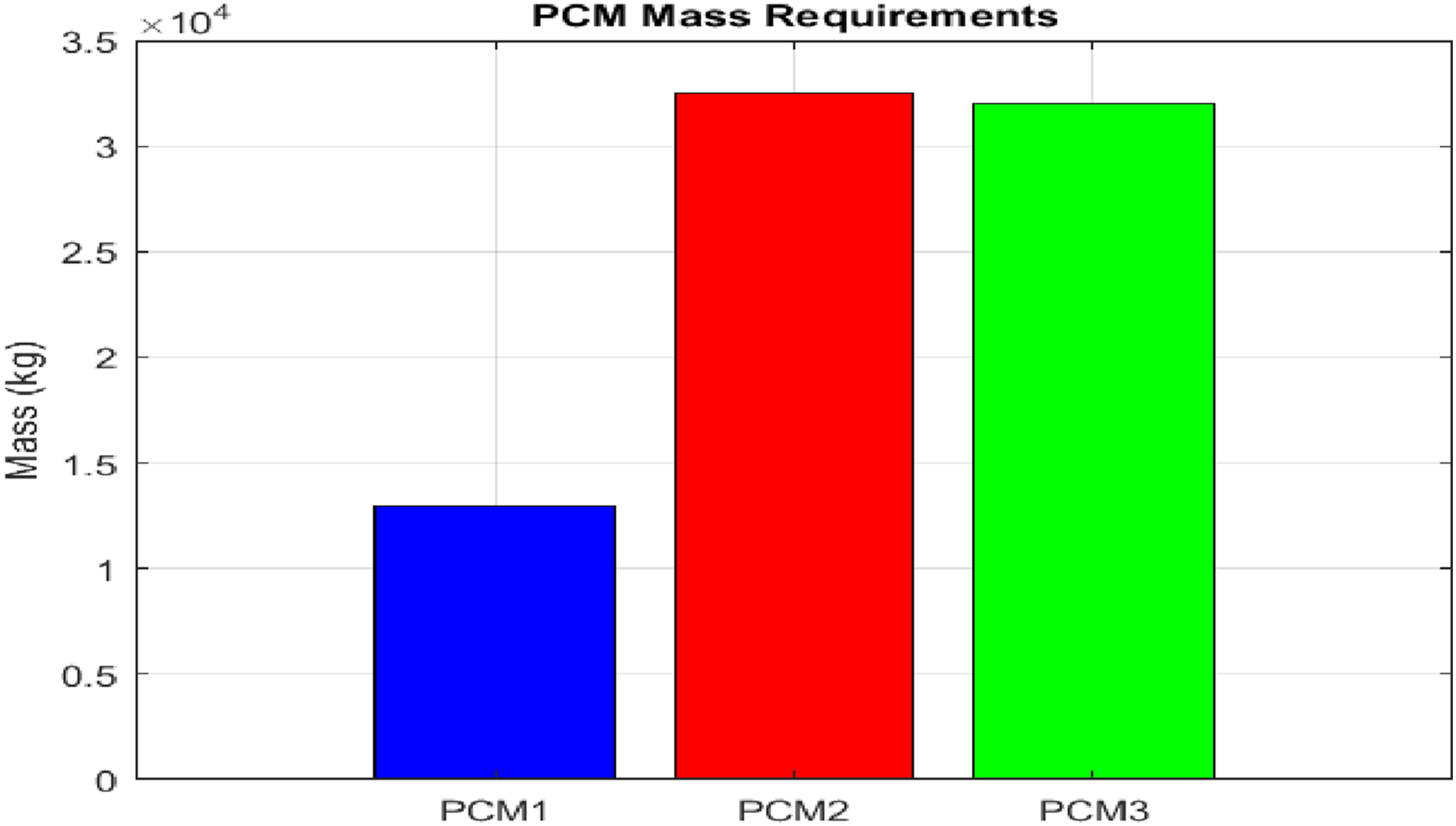
The mass needed for each PCM to cover the demand.
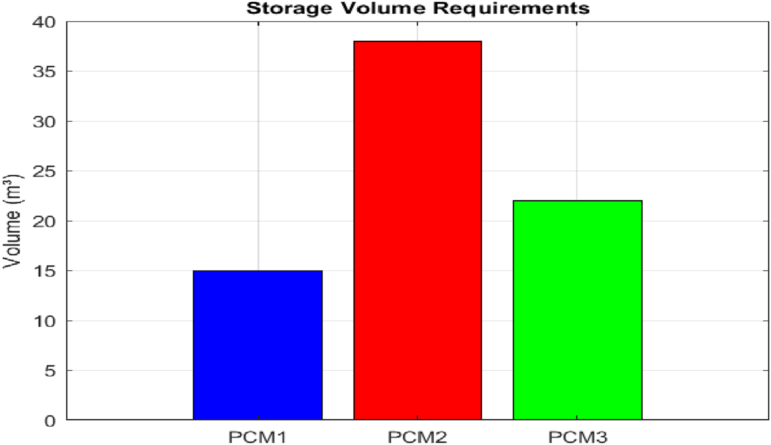
Storage volume requirements for the three PCMs.
Modeling in MATLAB
The design approach for this PCM’s thermal storage system involves a series of steps carried out across multiple MATLAB files. It begins by defining the system requirements, which detail the operational temperatures, mass flow rates, PCM properties, and design loads. It then calculates the energy, mass, and volume requirements for each PCM based on the design criteria. After that, it establishes the dimensions of the heat exchangers, setting parameters such as shell diameter, number of tubes, and heat transfer area. The thermal performance of the designed heat exchangers is subsequently evaluated, during which heat transfer coefficients are determined. To examine the system’s dynamic behaviour over time, it simulates fluctuations in temperature, phase transitions, and energy storage. Finally, it functions as an interface with TRNSYS, facilitating the model’s incorporation into larger system simulations.
The system comprises three distinct PCMs, each functioning at a different temperature level. PCM1 utilises paraffin with a melting point of −3°C, which is designed for freezing applications; PCM2 employs paraffin with a melting point of 4°C for refrigeration purposes; and PCM3 uses a salt hydrate with a melting point of 15°C for air conditioning applications. Each PCM is contained within a shell-and-tube heat exchanger, where NH3 (ammonia) circulates through the tubes during the charging process. At the same time, separate coolant circuits R134a for PCM1 and water for PCM2 and PCM3 manage the discharging process. The design process exemplifies a comprehensive approach to thermal energy storage, integrating material science, heat transfer principles, and system-level integration to achieve efficient and reliable performance.
Modeling in TRNSYS
The solar cooling system proposed in this study has been modeled using TRNSYS 18, a simulation tool widely employed for analysing renewable energy systems. The full simulation process is shown in the figure below. TRNSYS supports running MATLAB scripts through the Type 155 component (MATLAB link), which serves as a communication bridge enabling data exchange between TRNSYS and MATLAB.
Result
PCMs mass required
This chart illustrates the mass requirements for three PCMs used in a thermal storage system. PCM1 (blue) necessitates the smallest amount at around 13,000 kg, highlighting its lower energy storage role. PCM2 (red) and PCM3 (green) have significantly higher mass requirements—approximately 32,500 kg and 32,000 kg, respectively—due to their greater energy storage capacities and higher thermal loads. These mass values are influenced by both the specific latent heat of the materials and the design criteria of each PCM layer to meet varying cooling demands across temperature zones.
PCMs storage required capacity
This bar chart illustrates the storage volume requirements for the three PCMs used in the system. PCM1 (blue) requires the smallest volume at approximately 15 m3, while PCM2 (red) demands the largest volume, around 38 m3, due to its relatively low energy density and higher mass requirement. PCM3 (green) needs about 22 m3, which is less than PCM2 despite having a similar mass, indicating better volumetric efficiency. These differences reflect the combined effects of material density and thermal storage performance in sizing the storage tanks.
PCMs temperature evaluation
Figure 10 below shows the temperature profiles of the three selected phase change materials (PCM1, PCM2, PCM3) and NH3 over a time cycle, highlighting the charging and discharging performance of the thermal energy storage system. PCM1 fluctuates around its melting point of −3°C, indicating frequent charging and discharging due to the NH3 temperature often dropping below its melting point. PCM2 maintains a relatively steady temperature near its melting point of 4°C, suggesting it remains in a partially charged state or experiences slow thermal cycling. PCM3 has the most stable performance, consistently above its 15°C melting point, meaning it’s mostly in the liquid phase and not undergoing phase change often. The NH3 temperature varies dynamically, driving the heat transfer and phase change cycles of the PCMs, with noticeable cooling dips aligning with PCM1 and PCM2 transitions. Overall, this plot reflects a controlled cascade storage system, where each PCM layer interacts with NH3 to absorb or release heat according to its design temperature range. The temperature profiles of the three selected phase change and NH3 over time.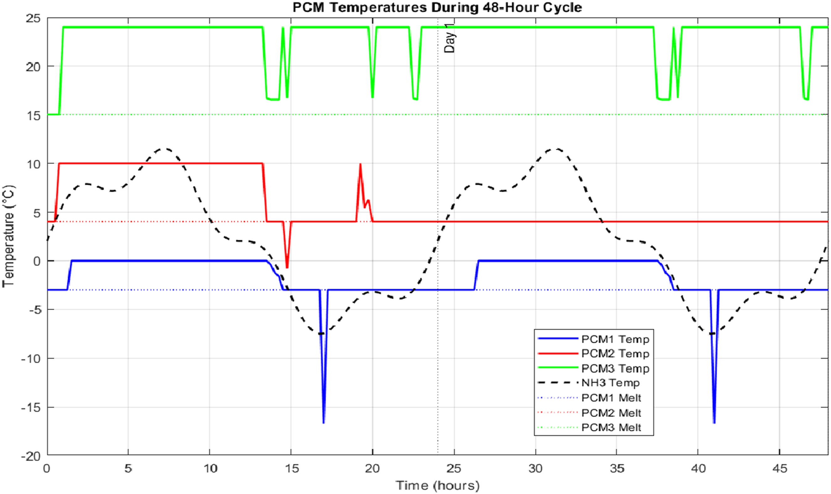
Heat transfer rate during the charging and discharging process
Figure 11 below illustrates the heat transfer behaviour of the three PCM units over a 48-h cycle, distinguishing between charging and discharging. PCM1 exhibits frequent charging at moderate rates (∼700 kW) and occasional light discharging, indicating it primarily stores cold energy during NH3 temperature drops. PCM2 experiences high charging rates (up to 4000 kW) but discharges infrequently, suggesting it functions as a thermal buffer with limited load activation. In contrast, PCM3 undergoes consistent charging and more regular discharging, reflecting its active role in meeting variable air conditioning demands. Overall, the system efficiently adapts to shifting thermal loads by distributing charging and discharging cycles among the PCM layers. The heat transfer behaviour of the three PCM units over time.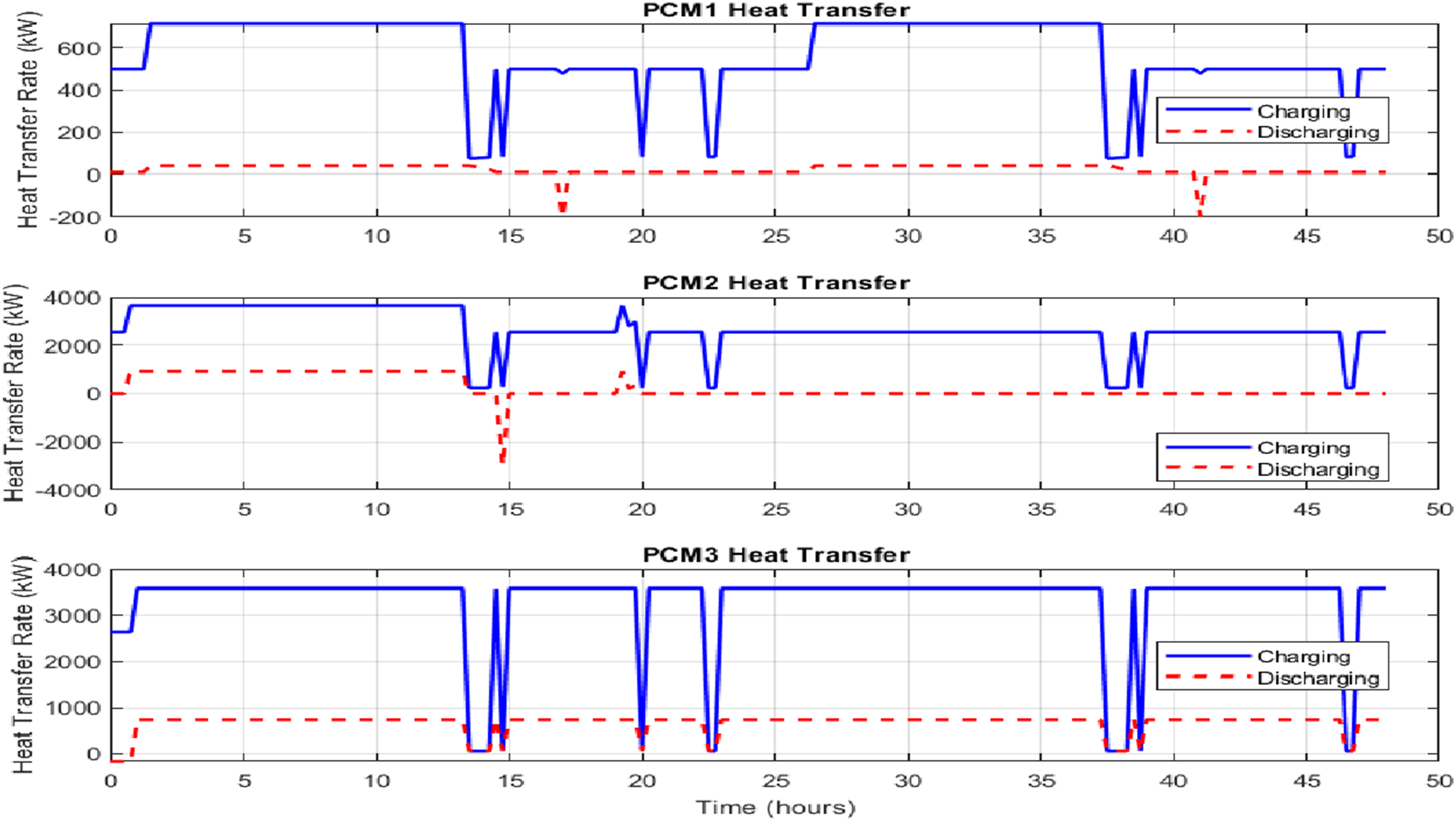
PCMs phase state
Figure 12 illustrates the phase state transitions of PCM1, PCM2, and PCM3 over a 48-h period, categorizing their behaviour into solid, melting, liquid, and solidifying phases. PCM1 exhibits the most dynamic behaviour, spending about 52% of the time in the liquid phase and 37% in melting, indicating frequent thermal cycling. PCM2 also shows significant phase activity, spending 61% of the time in the liquid phase and 28% in melting, suggesting it experiences partial charging with moderate variability. In contrast, PCM3 remains almost entirely in the liquid state (98%), with minimal time spent in melting and no solidifying, implying it stays above its melting point and contributes less to thermal buffering or load shifting. These results confirm a gradient of thermal engagement from PCM1 (most active) to PCM3 (least active), aligned with their respective temperature targets and demand profiles. The phase state transitions of PCM1, PCM2, and PCM3 over time.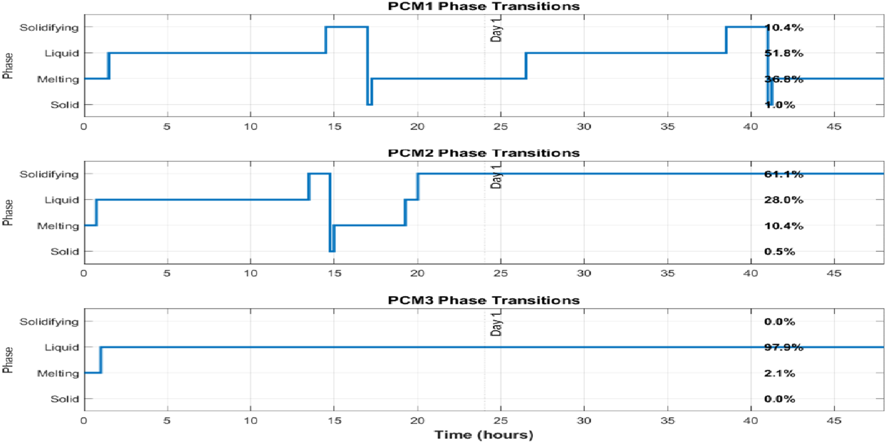
Energy storage evaluation
Figure 13 presents the energy storage performance of the PCM system. The top plot illustrates how energy accumulates in each PCM unit over 3 hours. PCM3 (green) reaches its maximum storage capacity quickly and remains nearly constant, while PCM2 (red) accumulates energy at a slower rate, and PCM1 (blue) shows the least storage, with fluctuations indicating active charging and discharging. The total energy stored (black dashed line) plateaus early, reflecting that PCM3 dominates early-stage storage. The bottom bar chart summarizes the final energy distribution: PCM2 stores the most energy (9437.8 MJ, 49%), followed by PCM3 (8100 MJ, 42%), while PCM1 contributes just 9% (1791.7 MJ). This highlights the system’s reliance on mid- and high-temperature PCMs for bulk energy storage, while PCM1 plays a smaller, more responsive role. The energy storage performance of the three PCMs storage.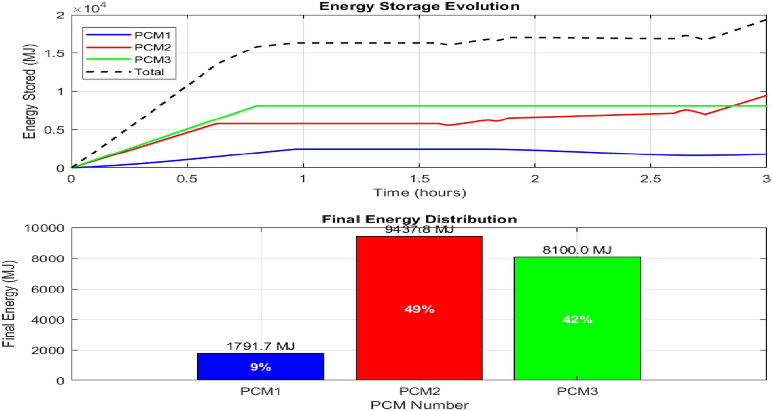
Cooling load met
Figure 14 illustrates the hourly cooling energy successfully delivered by a solar-powered cooling system for the beginning of July. It shows the energy demand met for freezer, fridge, and air conditioning. Indicate that the solar cooling system effectively meets the full demand of all three levels throughout the period, demonstrating its reliability and responsiveness during high-load summer days. This confirms the system’s suitability for sustainable operation under peak summer conditions. Cooling energy successfully delivered by a solar-powered cooling system.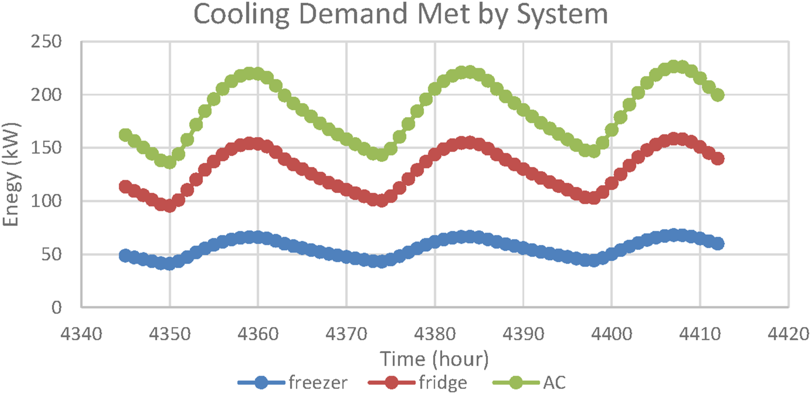
Electricity consumption
Figure 15 compares the electricity consumption profiles of multiple cooling system configurations over a representative period in early July, highlighting their operational efficiency and potential for energy savings. The traditional vapor-compression cooling system exhibits a constant high electricity demand throughout the day, serving as a baseline for comparison. In contrast, the initial design of a solar cooling system with sensible heat storage shows a fluctuating demand between 200 and 850 kW, reflecting the system’s sensitivity to solar availability and load variation. The optimised version of this design significantly reduces electricity consumption, maintaining operation mostly below 300 kW, with pronounced reductions during solar peak hours. The solar cooling system with cold PCM storage demonstrates a stepwise pattern with peaks up to 1170 kW, while the hybrid hot/cold PCM system achieves the lowest and flattest demand curve, reflecting maximum utilisation of solar and thermal storage capabilities. These results underline the superior performance of PCM-integrated systems, particularly the hot/cold configuration, in minimising reliance on electrical input and maximising energy efficiency under high ambient load conditions. Electricity consumption profiles of multiple cooling system configurations in early July.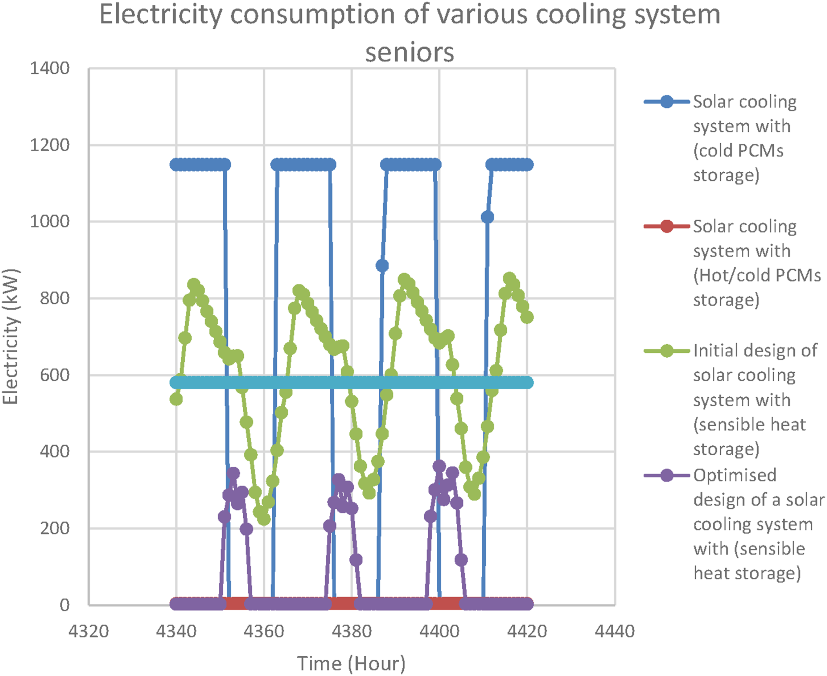
Cost analysis
The cost analysis of phase change materials (PCMs) for cooling systems reveals significant economic and environmental benefits, particularly in regions with high cooling demands. PCMs are effective thermal energy storage solutions, allowing for energy savings and reduced carbon emissions. The following sections outline key aspects of this analysis.
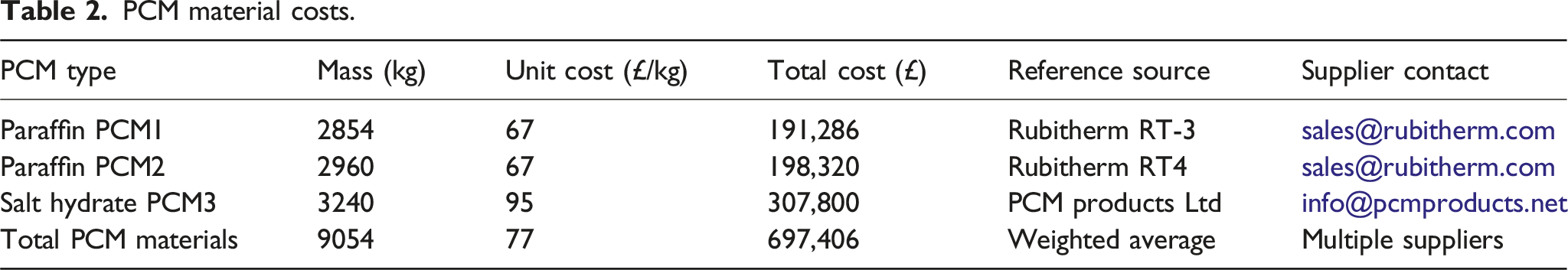
PCM material costs
PCM material costs.
Heat exchanger costs
Heat exchanger costs.
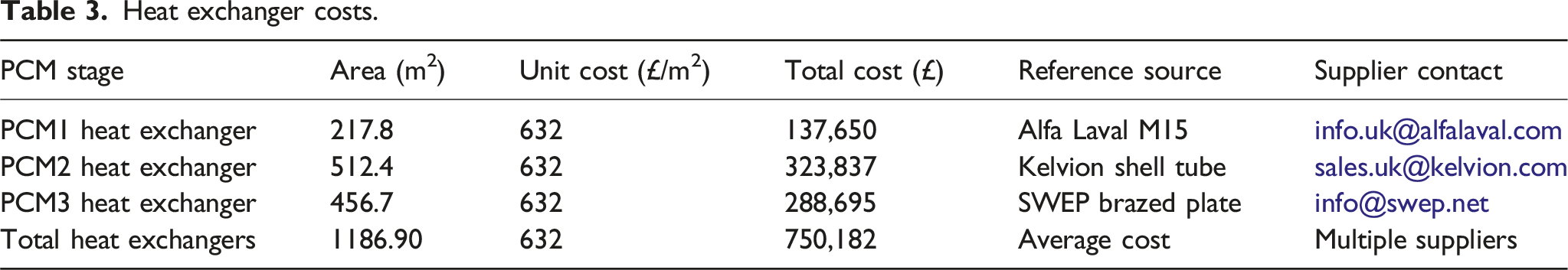
While heat exchangers represent approximately one-third of the total system cost, this share can be significantly reduced through design and manufacturing optimisation. The current analysis assumes commercial-grade shell-and-tube exchangers fabricated from stainless steel; however, adopting compact brazed-plate or spiral heat exchangers with enhanced surface-area density could decrease material use and cost. Moreover, using modular exchanger assemblies would simplify maintenance and allow partial replacement rather than full unit substitution. Incorporating high-conductivity fins or composite thermal interfaces could further improve heat-transfer efficiency, reducing the required surface area for the same duty. These alternatives provide practical routes for cost reduction while maintaining the thermal reliability required for PCM charging and discharging operations.
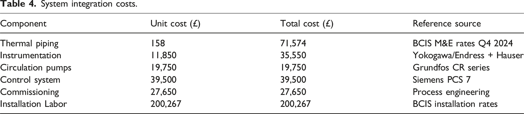
System integration costs
System integration costs.
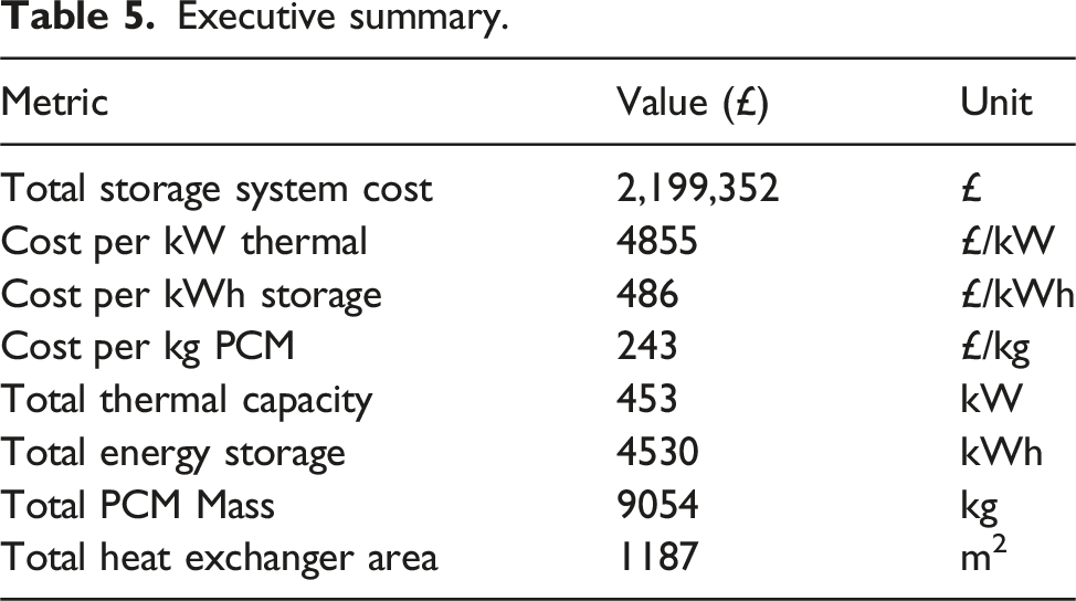
Executive summary
Executive summary.
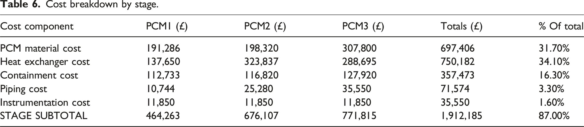
Cost breakdown by stage
A stage-wise financial analysis indicates that PCM3 represents the most expensive stage at £771,815, primarily due to its high costs for materials and heat exchangers. PCM2 follows at £676,107, while PCM1 is the least costly at £464,263. Across all stages, heat exchangers (34.1%) and PCM materials (31.7%) comprise the majority of expenses. Containment structures account for 16.3%, while piping, instrumentation, and control systems contribute smaller but critical portions. The subtotal of these components constitutes 87% of the total system cost, highlighting the necessity of optimising material selection and component sizing.
By expressing all costs in functional and percentage terms rather than supplier-specific figures, the analysis maintains general applicability and aligns with standard academic reporting conventions.
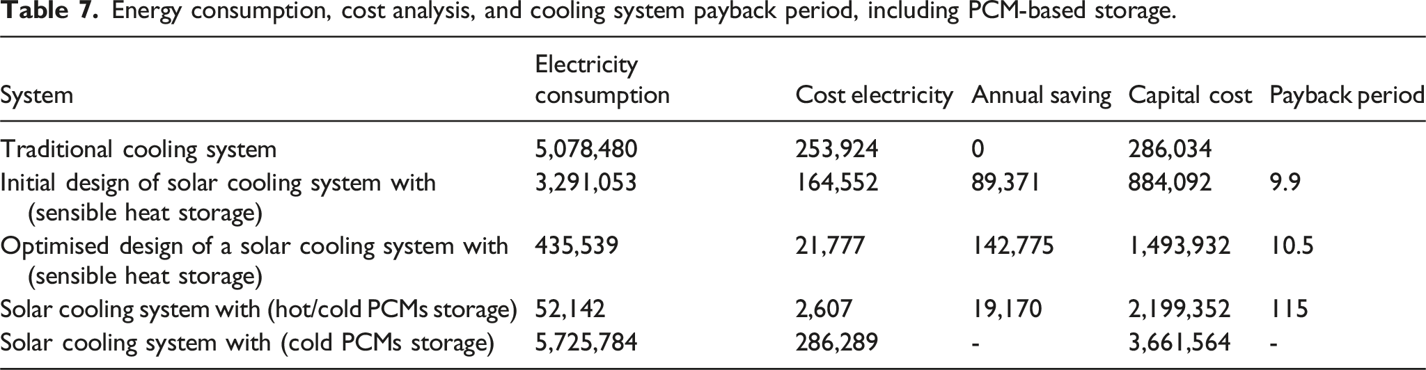
Payback period of various cooling systems for seniors
The comparative payback period analysis of various cooling system configurations reveals significant disparities in energy efficiency and financial viability. The traditional vapor compression system, despite its relatively low initial capital cost (£286,034), incurs the highest annual electricity consumption (5,078,480 kWh) and cost (£253,924), resulting in no annual savings or viable payback. In contrast, the initial solar thermal cooling design demonstrates a marked reduction in electricity consumption to 3,291,053 kWh. It achieves annual savings of £89,371.35, yielding a payback period of approximately 9.9 years on a capital investment of £884,092. A further optimised configuration reduces electricity demand to 435,539 kWh and increases annual savings to £142,775.65, although with a higher capital cost of £1,493,932, resulting in a modestly extended payback period of 10.5 years. Notably, the cascade PCM storage system achieves the most significant energy reduction, consuming only 52,142 kWh annually, with an associated electricity cost of £2607. However, due to its substantial capital cost of £2,199,352, the annual savings of £19,170 yield an unfeasibly long payback period of 115 years. This underscores a critical trade-off: while the PCM-based system excels in energy efficiency and long-term operational cost reduction, its current economic viability is severely hindered by high initial investment. These findings suggest that without substantial cost reductions in PCM materials and system components, the adoption of PCM storage in large-scale cooling applications may remain limited from a purely financial perspective.
Although the calculated payback period of approximately 115 years appears economically unfeasible for immediate commercial deployment, it primarily reflects the high initial investment associated with PCM materials and shell-and-tube heat exchangers. In particular, these two components constitute more than 65 % of the total capital expenditure, dominating life-cycle costs despite excellent operational savings. It should also be noted that the financial model excludes potential incentives such as renewable energy subsidies, and carbon credits, all of which could substantially shorten the payback period. Furthermore, the cascade storage units, local fabrication of containment structures, and the use of low-cost or composite PCMs could collectively reduce total capital cost, bringing the payback period closer to the 8–15-year range typically reported for advanced solar-cooling technologies. Therefore, the extended payback period should be viewed not as a limitation of the thermal concept itself but as an indicator of where cost-optimisation research and policy support are most needed.
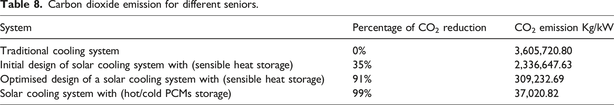
CO2 evaluations of various cooling systems for seniors
Table 8 below illustrates the percentage reduction in CO2 emissions along with the corresponding emission levels (in kg/kW) for four different cooling system configurations. The traditional system serves as the baseline with no reduction and emits the highest amount of CO2. The initial design of a solar thermal cooling system achieves a 35% reduction. Further optimisation significantly enhances performance, reducing emissions by 91%. The system with cold PCM storage demonstrates the most substantial environmental improvement, attaining a 99% reduction and emitting only 37,020.82 kg/kW for the use of pumps and control panels. These results underscore the considerable potential of advanced thermal storage technologies, particularly PCMs, in improving energy efficiency and minimising environmental impact in cooling applications.
The environmental implications of the reported CO2 reduction can be contextualised by considering typical carbon pricing and emission policy frameworks. Using an average 2024 global carbon price of £45–60 per tonne CO2 (UK ETS data), the avoided emissions from the PCM-based solar cooling system approximately 3.57 × 10⁶ kg CO2 annually compared with a conventional system would correspond to a potential monetary saving of £160,000–£215,000 per year in carbon offset value. This scale of reduction positions the cascade PCM design as highly attractive under emerging carbon neutrality targets for industrial refrigeration and cold chain applications. The result demonstrates that, beyond direct energy savings, integrating PCM storage in solar cooling systems provides measurable economic benefits in carbon pricing contexts and aligns with the 2050 Net Zero strategies adopted in the UK and EU.
A qualitative sensitivity assessment was conducted to evaluate how variations in major economic and environmental parameters could influence the results. The payback period and levelised cost of cooling (LCOC) are particularly sensitive to changes in electricity tariffs, PCM unit prices, and system scale. A ±20 % variation in electricity cost would modify the annual savings by approximately ±25 %, while a similar variation in PCM material cost could shift the overall payback period. Scale effects also play a crucial role: doubling the system capacity is projected to reduce the unit capital cost by nearly 30 % due to improved equipment utilisation. Furthermore, the inclusion of carbon credit valuation estimated at £40–60 per tonne CO2 avoided would reduce the effective payback by 10–15 years. These trends indicate that, under supportive electricity pricing and carbon policy conditions, the techno-economic performance of cascade PCM systems could become competitive with other solar-cooling options.
Although the presented results are deterministic, several sources of modelling uncertainty were evaluated qualitatively to assess their potential influence on the outcomes. The main uncertainties arise from the thermal conductivity and latent heat of the PCMs, which can vary by about ±10–15% due to differences in manufacturing purity and operating cycles. Heat transfer coefficients were derived from empirical correlations, carrying an estimated ±8 % uncertainty in the predicted charging and discharging rates. Additionally, solar irradiance and ambient temperature fluctuations were modelled using typical meteorological year (TMY) data, which may deviate from actual field conditions by ± 5 %. A sensitivity check indicated that a combined ±10 % variation in these parameters would cause less than ±7 % change in total stored energy and ±5 % in predicted electricity savings. Therefore, while uncertainty exists, its magnitude does not significantly adjust the principal findings or comparative trends reported in this study.
Cost breakdown by stage.
Energy consumption, cost analysis, and cooling system payback period, including PCM-based storage.
Carbon dioxide emission for different seniors.
Discussion
Contrasting earlier PCM TES modelling studies that primarily focused on individual temperature zones or single-stage storage, the present research advances a multi-temperature, cascade PCM configuration capable of simultaneously serving three distinct cooling demands. This integration strategy not only provides dynamic thermal balancing across −4°C to 22°C but also introduces a new system-level methodology linking component-scale PCM behaviour with full solar-cooling network performance through MATLAB–TRNSYS co-simulation. The findings from this conceptual and numerical reveal specific design insights such as the dominant contribution of PCM2 and PCM3 to overall storage and the limited cycling efficiency of PCM1 which have not been previously reported in comparable PCM TES investigations. Therefore, although the work is based on modelling, it yields novel design and operational perspectives that extend current understanding of cascade PCM performance for multi-load solar cooling applications.
The simulation and design outcomes of the cascade PCM thermal storage system demonstrates the effectiveness of thermally stratified PCMs in managing variable cooling loads. The selection of three distinct PCMs, including paraffin types for lower temperature applications and a salt hydrate for higher temperature storage, allowed for targeted thermal management throughout the temperature spectrum.
Material performance analysis revealed that PCM1 was highly responsive, frequently charging and discharging due to its alignment with NH3’s low-temperature fluctuations. This indicates its suitability for transient or short-cycle freezing loads. Conversely, PCM2 and PCM3 acted more as thermal buffers, storing larger amounts of energy, with PCM2 demonstrating notable melting and solidifying behaviour, while PCM3 maintained a mostly liquid phase throughout the cycle. This suggests that PCM3 may be oversized or not fully engaged in active thermal buffering, which could inform future design optimisations.
The simulation results also indicate that PCM3 (15°C salt hydrate) remains in the liquid phase for approximately 98 % of the operating cycle, suggesting a degree of overdesign or limited engagement in active energy buffering. This behaviour can be attributed to the relatively narrow temperature difference between the discharge fluid (water loop) and the PCM’s melting point, resulting in incomplete solidification during cyclic operation. To address this inefficiency, future designs could consider either reducing the PCM3 volume or selecting a material with a slightly higher melting point (e.g., 17–18°C) to enhance the temperature gradient and improve phase-change utilisation. Alternatively, integrating an auxiliary sensible storage layer or optimising control logic to promote deeper discharging could balance the energy contribution among PCM layers. These adjustments would increase the thermal effectiveness of the high-temperature zone and enhance the overall storage utilisation of the cascade system.
Heat transfer and phase state analysis revealed that each PCM had distinct thermal behaviours: PCM2 experienced the highest charging power, while PCM3 exhibited more consistent discharge patterns aligned with air conditioning loads. The integration of shell-and-tube heat exchangers facilitated effective heat exchange, although improvements in the thermal conductivity of paraffin materials could enhance the system’s responsiveness.
To address the low thermal conductivity of paraffin PCMs, several enhancement techniques can be adopted in future system designs. Embedding high-conductivity fins or metal matrices within the PCM capsules can significantly accelerate heat transfer during both melting and solidification. Alternatively, developing composite PCMs through the addition of nanoparticles such as Al2O3, CuO, or expanded graphite has been experimentally shown to increase effective thermal conductivity while maintaining phase stability. Encapsulation of these composite PCMs within aluminium or copper shells could further improve heat flux and charging rates. Integrating such conductivity enhancement strategies would not only improve thermal response but also reduce the required heat exchanger area, indirectly lowering system capital cost.
System integration with TRNSYS and MATLAB demonstrated the robustness of the co-simulation platform, particularly in evaluating temporal energy storage dynamics and validating charging/discharging cycles. The Type 155 link enabled real-time interaction between modeled control strategies and physical thermal behaviours, which is essential for optimising operational control of PCM-based storage systems.
It is acknowledged that the present study is based solely on numerical co-simulation without direct experimental validation. However, the modelling approach is firmly grounded in experimentally verified correlations for heat transfer, PCM thermophysical properties, and TRNSYS component performance data. The objective of this phase was to establish a validated methodological framework that can guide prototype development and experimental testing in subsequent work. The co-simulation results provide realistic thermal and economic trends consistent with published empirical data, ensuring that the findings are representative and practically applicable despite the current simulation-based scope.
Although experimental validation was not conducted in this study, the modelling approach was benchmarked against trends and data reported in prior experimental investigations. For example, Miccoli et al. (2024) and Ismail et al. (2023) experimentally characterised PCM charging/discharging behaviour in small-scale cooling systems and observed latent-heat utilisation patterns consistent with those reproduced in the present simulations. Similarly, Masood et al. (2023) and Chandra et al. (2023) showed that paraffin and salt-hydrate PCMs maintain stable temperature plateaus and effective energy storage during repeated cycles, supporting the thermophysical assumptions applied in this study. However, to the best of the authors’ knowledge, no experimental work has yet been reported on cascade PCM storage systems designed for low-temperature multi-load applications such as freezing, refrigeration, and air-conditioning combined within a single configuration. Therefore, this study provides the first simulation-based evaluation of such a system, offering a framework that can inform and guide future experimental prototypes. The close agreement of the predicted melting–solidification dynamics and thermal gradients with previously reported single-stage PCM experiments reinforces the physical validity of the proposed cascade model.
The engineering relevance of the modelled results has been carefully considered by grounding all heat-transfer and phase-change parameters in experimentally validated correlations. Convective and conductive heat transfer coefficients were derived from empirical relationships reported by Oró et al. (2012) and Miccoli et al. (2024), ensuring that the simulated charging and discharging rates fall within realistic operational ranges. The stratification in the cascade storage tank was modelled using density-based layering assumptions, representing the natural buoyancy-driven separation commonly observed in experimental PCM systems. Furthermore, the cycling stability of the selected paraffin and salt-hydrate PCMs is supported by published studies showing minimal performance degradation. Although small-scale factors such as incomplete insulation, thermal bridging, and contact resistance were not explicitly included in the model, their effect on the overall thermal behaviour is expected to be minor. Future experimental work will account for these factors to validate the engineering behaviour observed in this simulation-based study.
From an economic standpoint, the results reveal a significant challenge. Although the system reduces electricity consumption by over 94% compared to traditional vapor compression systems, the initial capital cost of £2.2 million leads to a payback period of approximately 115 years. This lengthy payback horizon severely limits the financial attractiveness of the current design, especially in markets where electricity costs are relatively low. Most of the capital burden is attributed to PCM materials, heat exchangers, and integration components. These findings emphasize that while PCM storage is technically mature, economic feasibility depends on cost reductions in PCM materials and system simplification.
As summarised in Table 7, multiple system configurations were analysed to assess payback under different design scenarios from traditional vapour-compression cooling to solar-assisted systems with sensible and cascade PCM storage. While the cascade PCM configuration achieved the highest energy savings and CO2 reduction, it also showed the longest payback period because of its high capital strength. To mitigate this, several reduction strategies can be considered. First, implementing government motivations or renewable-energy grants could significantly offset capital costs, particularly in developing regions promoting solar-thermal technologies. Secondly, modularising the PCM storage units would enable phased installation based on cooling-load demands, enhancing scalability and lowering initial costs. Third, the adoption of alternative or locally sourced PCMs such as bio-based paraffins or industrial-grade salt hydrates can lower material cost Moreover, hybridisation with lower-cost storage options (e.g., chilled-water or sensible-heat tanks) could provide complementary load coverage. Finally, linking the system’s environmental benefits to carbon-credit trading or time-of-use electricity tariffs could further improve financial feasibility. Together, these measures would meaningfully shorten the payback period highlighted in Table 7 and enhance the overall economic attractiveness of cascade PCM-based cooling systems. The sensitivity outcomes further underline that the system’s financial viability is strongly dependent on electricity tariffs and carbon-credit values, both of which vary regionally and temporally.
While the current design demonstrates outstanding energy and CO2 performance, its economic feasibility remains constrained by material and integration costs. Future work should prioritise cost-reduction strategies and policy-driven financial mechanisms to enable realistic payback scenarios.
Limitations and future work
While this study provides a techno-economic-environmental (3E) evaluation of a cascade PCM-based solar cooling system, several limitations should be acknowledged. First, the investigation is based solely on numerical co-simulation; therefore, experimental validation is required to confirm the practical heat-transfer performance, thermal stratification, and long-term stability of the PCMs under real operating conditions. Second, the relatively low thermal conductivity of paraffin PCMs constrains heat-transfer rates, suggesting that future studies should explore composite PCMs enhanced with nanoparticles, metal foams, or expanded graphite to improve charging and discharging efficiency. Third, encapsulation and containment optimisation should be examined to prevent phase segregation and enhance cyclic reliability. Fourth, greater system modularity and the integration of hybrid sensible–latent storage configurations could reduce capital cost and improve scalability for industrial and commercial applications. Fifth, further analysis should incorporate dynamic techno-economic scenarios, including carbon-credit valuation, electricity-tariff evolution, and local manufacturing cost reductions, to evaluate the system’s financial resilience under different market and policy conditions. Finally, coupling the present framework with life-cycle assessment (LCA) tools would enable a more holistic understanding of the environmental footprint, reinforcing the sustainability potential of cascade PCM-TES technology for future low-carbon cooling applications.
Conclusion
The developed cascade PCM thermal energy storage system presents a promising solution for managing multi-level cooling demands through stratified thermal storage. The integration of paraffin and salt hydrate PCMs with specially designed melting points facilitates efficient load matching, thermal buffering, and energy shifting. Simulation results confirm that the mid- and high-temperature PCMs store the majority of energy, while the low-temperature PCM is crucial for rapid response to freezing demands.
The co-simulation of MATLAB and TRNSYS provided a comprehensive evaluation framework that confirmed the dynamic thermal behaviour, energy storage performance, and system scalability. Despite the system’s promising performance, further research is recommended to enhance PCM thermal conductivity, reduce system complexity, and assess real-world operation over extended periods. Overall, this study contributes to the growing body of research supporting PCM integration into solar-assisted cooling and highlights key design principles for efficient, multi-zone thermal management systems.
However, the economic analysis revealed a critical limitation: the payback period for the PCM-based storage system exceeds 115 years due to substantial upfront costs, despite significant energy savings. While the system achieves notable reductions in electricity consumption, the financial return remains unviable under current market conditions. This underscores the need for future research to focus on cost-reduction strategies, such as novel encapsulation methods, cheaper composite PCMs, and modular integration. Overall, the study contributes to the field of solar-assisted cooling by providing a comprehensive thermo-economic evaluation. While the system is thermally effective and environmentally aligned, it must overcome key financial barriers to enable broader adoption, especially in regions with constrained capital budgets. This study thus goes beyond conceptualisation by delivering new system-level insights into multi-temperature PCM integration and energy stratification, offering a framework that future experimental validation can build upon.
Footnotes
Declaration of conflicting interests
The authors declared no potential conflicts of interest with respect to the research, authorship, and/or publication of this article.
Funding
The authors received no financial support for the research, authorship, and/or publication of this article.