
Abstract
The paper provides thermodynamic analysis of an energy storage concept in which thermal stores are coupled with the feedwater heating train of nuclear-powered steam plant. This allows the electrical output of the plant to be flexed whilst maintaining constant reactor power, thereby providing the equivalent of an electricity storage system and facilitating the adoption of a load-following role for nuclear plant. The concept falls under the umbrella of ‘generation-integrated energy storage’, which exploits existing hardware required for generation to reduce storage costs, and benefits also from fewer energy transformations when compared to ‘electricity-in-electricity-out’ forms of storage. This means that a high (effective) round-trip efficiency can be achieved at low cost. An important feature of the proposed system is that the turbine bleed flows (at their various pressures and temperatures) automatically provide good thermal matching with the feedwater temperature profile, so that heat can ultimately be transferred to and from sensible-heat thermal-storage media with high exergetic efficiency. Various options are discussed for the thermal stores, including pressurised water tanks, thermal oils and packed beds. The analysis also includes consideration of the off-design behaviour of cycle components.
Keywords
Introduction
The future of nuclear power within the UK, and indeed worldwide, is both uncertain and controversial, with many of its opponents pointing out that the cost of electricity generated from nuclear plant significantly exceeds that from renewable sources such as wind and solar energy. A recent report from the UK government’s Department of Business, Energy and Industrial Strategy (BEIS)1,2 gives levelised costs of electricity in the ranges 39–52 £/MWh for onshore wind, 51–63 £/MWh for offshore wind, 39–51 £/MWh for large-scale solar PV and 85–123 £/MWh for nuclear plant (projected commissioning in 2025, in real 2018 prices). These suggest a clear cost advantage for renewable technologies, but making comparisons on a cost-per-MWh basis alone is misleading because other aspects of generation – such as continuity of supply and dispatchability – have a value that is difficult to quantify (see, for example, the discussion on ‘value-adjusted’ levelised costs in Ref 3). Ultimately it is the overall system cost that matters when it comes to comparing different generation mixes.
Wind and solar resources are well known for being intermittent, variable and non-dispatchable, and their increased penetration on the grid is therefore expected to lead to greater system-balancing challenges. As an example, data available from Ref 4 show that there were ten occasions during 2020 when output from the UK’s inventory of (metered) wind turbines remained below a quarter of its average value (i.e., below
Generation-integrated energy storage
Garvey et al. 7 have set out the advantages of ‘generation-integrated energy storage’ (GIES) relative to ‘pure’ or ‘electricity-in-electricity-out’ (EIEO) storage systems. As the name suggests, EIEO involves taking electrical energy from the grid or distribution network during charge and returning it (minus losses) during discharge. It is typified by electrochemical batteries and pumped-hydro storage. By contrast, GIES usually entails storing some intermediate form of energy prior to its conversion to electricity. This has the advantage that (i) fewer energy transformations are required, thereby permitting high round-trip efficiency, and (ii) existing power-conversion hardware can be exploited such that storage can be implemented relatively cheaply. By integrating storage and using the generator’s existing electricity conversion pathway, previously non-dispatchable electricity generators become dispatchable.
For nuclear plant, the obvious intermediate energy form is thermal energy from the nuclear reaction. There are various ways in which this can be stored, as described below, but the chief thermodynamic benefit stems from avoiding some of the generation losses during charge since storage occurs prior to generation. This means that the exergy (available energy) transferred to storage can exceed the deficit in electrical work output, giving an apparent charging efficiency greater than 100% – a situation clearly impossible for EIEO systems.
Historical context
The integration of thermal storage into steam plant can be traced back as far as the 1890s, as described in the accounts by Gilli & Fritz 8 and Gilli et al. 9 Early designs involved oversizing the boiler drum such that it served as an integrated accumulator, but the advent of the sliding-pressure (Ruth’s) accumulator in 1913 allowed stand-alone storage to be located elsewhere within the plant. The Charlottenburg coal-fired power station in Berlin was the first to incorporate this type of storage, employing sixteen such accumulators (each 4.5 m diameter and 21 m high) to supply a separate peaking turbine.
The first proposal for feedwater-integrated storage appears in a series of patents filed in the 1920s and 1930s by the German engineer Marguerre.10,11 These show how feedheat steam extraction rates can be adjusted so as to match the load. Marguerre estimated that this approach would reduce storage costs, but he did not discuss its thermodynamic benefits.
In 1958 Margen and Carruthers filed a Swedish patent for a system that employed a large accumulator connected in parallel with the steam generator for nuclear plant. 12 Conscious of the high cost of steel pressure vessels they accordingly proposed the use of underground, thermally-insulated rock caverns. This work was rekindled some 15 years later when Margen combined his rock cavern concept with Marguerre’s feedwater storage system. 13 Around the same time Gilli and Fritz undertook research into an ‘integrated steam accumulator for load peaking’. 8 This focused on steel accumulators supplied from the superheated steam generator and coupled to a separate peaking turbine, but the possibility of over-designing the main turbine set is also discussed. It is worth mentioning, however, that steam accumulators suffer a similar drawback to compressed-air caverns in that the pressure falls as fluid (in this case steam) is withdrawn. This causes practical difficulties for the turbine (which can be resolved by throttling to the lowest operating pressure), but also means that the full capacity of the accumulator cannot be exploited.
In the late 1970s the US government commissioned a number of state-of-the-art studies9,14–18 into integration of thermal storage with both coal and nuclear plant. Hausz et al.,16–18 for example, screened forty different concepts and modelled the twelve most promising ones. Their results suggested that the lowest cost options for nuclear plant were for feedheating/feedwater systems with sensible heat storage, either as pressurised water in prestressed cast iron vessels, or ambient-pressure packed beds combined with oil. At the time, however, the conclusion was that thermal storage was not viable, being only marginally competitive with cycling of coal plant or peaking gas turbines. 18
Recent work
Over the past decade the motivation for storage has shifted to tackling the intermittency of renewable generation. Many papers have been published on nuclear-integrated storage, with notable contributions from the Massachusetts Institute of Technology,19,20 Idaho National Laboratory,21–23 the University of Minnesota24–26 and various institutions in South Korea.27,28 In nearly all cases the intention is to provide flexible electrical output whilst maintaining constant reactor power, thereby fully exploiting the most costly part of the plant and avoiding problems of thermal cycling. Frick et al. 29 also explore supplying process steam and/or cooling, rather than returning the stored energy as electricity. The concepts emerging from these publications differ in terms of (a) the location from which heat is extracted, (b) whether the storage is discharged via the existing plant or has its own, separate generation system, and (c) the type of storage medium (e.g., latent heat or sensible heat).
Frick et al. 22 conclude that the best place for heat (steam) extraction is upstream of the turbine control valve as conditions here are most stable. They propose two-tank sensible heat storage, although the reasons for this choice are unclear. The difficulty is that the majority of energy available from the steam is in the form of latent heat, so that transfer of this energy to sensible heat storage incurs a large exergetic loss. This means that, during discharge, steam is returned to the LP (rather than the HP) turbine. 23
Carlson et al. 24 initially propose a system in which steam is taken from upstream of the HP turbine and returned (after some form of generic storage) via the LP turbine, arguing that a significant (9.8%) increase in plant capacity factor can be achieved without change to the components. This is contingent upon the turbines being able to achieve 110% of baseload power, which they justify on the basis of manufacturers’ data. In later work, Carlson & Davidson 26 examine different steam diversion locations and different storage options, which they compare on the basis of an ‘energy production ratio’ (the ratio of electrical energy produced in a 24-h period with and without storage) and ‘discharge power ratio’ (the ratio of net discharge power with and without storage). These metrics will be highly dependent on the profile of demand so will not necessarily translate to other electricity systems. The authors conclude that the greatest benefit is attained when diverting steam from before the LP turbine (i.e., after moisture separation and reheating) in combination with multistage storage, comprising both latent-heat and sensible-heat materials.
Work by Amuda & Field 27 is focused on the practicalities of integrating storage with the Korean APR1400 PWR plant. They propose storage in an ‘Oil Storage Tank Farm’, comprising multiple packed beds with sufficient heat transfer oil to fill only those that are active (see the Thermal storage options section). The charging process diverts steam from the steam generator, returning it to the deaerator after condensation. Several options are considered for discharge, including using the stored thermal energy to heat the HP feedwater, or using it to raise LP steam. The authors observe that it is possible to flex the turbines for the APR1400 plant from −22% to +11% and suggest this would be similar for other PWR designs.
In the UK, there have been recent studies on thermal storage in conjunction with both PWR plant (Al Kindi et al.) 30 and AGR plant (Romanos et al.). 31 In both cases the proposed concepts store energy in latent-heat media (e.g., sodium nitrate/hydroxide mixtures) and discharge via secondary generating systems – i.e., steam and organic Rankine cycles respectively. The use of secondary cycles is proposed on the basis that they allow greater increases in output (estimated at 23% and 32% respectively) without substantive modification to the existing components. This argument probably holds true when retrofitting existing plant (for which there will be diminishing opportunity), but for future plant it may be more cost-effective to extend the capacity of the main cycle components at the design stage.
Future generations of reactors provide excellent opportunities for integrating storage. For example, Denholm et al. 32 and Edwards et al. 33 describe concepts in which heat from either a helium-cooled reactor or a molten-salt reactor is transferred to the power cycle via an intermediate molten salt loop, which can readily incorporate storage tanks similar to those deployed for concentrated solar power. The large temperature lift of the primary coolant (for the helium reactor in particular) leads to high energy densities and consequently very cost-effective storage.
Scope of the present study
It is notable that feedheat/feedwater storage has been largely overlooked in much of the recent work and the focus has instead been upon extracting heat from live steam, usually combined with storage in phase-change materials (PCMs). As Saeed et al. 34 note, however, transferring heat in and out of PCMs is less straightforward than for sensible heat media, essentially because the heat-exchange network has to permeate all of the storage vessel. Storage systems coupled with the feedheat train integrate easily with sensible heat storage and allow heat to be transferred in an exergetically efficient fashion. A detailed thermodynamic analysis of such systems has not, however, appeared in the literature so far. The aim of this paper is to provide such an analysis, with a focus on explaining the thermodynamic concepts. The analysis is presented for PWR plant, but the storage could equally be coupled to other types of plant – including conventional and biomass-fuelled steam cycles.
The structure of the paper is as follows. The subsequent section describes a simplified control-volume analysis with the aim of demonstrating the relationship between ‘excess feedwater fraction’ and the deficit/surplus in work output. This is followed by sections which describe a more detailed plant model and its performance (including component off-design operation). A comparison of different options for the thermal stores is then given and, finally, there is a section which discusses various practical considerations of the proposed system.
Simplified analysis
In order to illustrate the principles of operation we consider first the simplified steam cycle shown in Figure 1(a). This avoids complications associated with moisture separation and reheat, but nonetheless captures the main features of the feedwater storage concept. (Computational analysis of a more realistic cycle, representative of PWR plant, will be presented in the System performance section) The simplified cycle is essentially the standard Rankine cycle with n stages of regenerative, indirect-contact feedheat. The aim is to keep conditions around the cycle and the mass flow through the steam generator as near as possible to their design values in order to minimise interference with the operation of the reactor. The analysis below is accordingly presented in terms of quantities per unit mass flow through the steam generator. (a) Simplified steam plant layout indicating connection to storage, and steam bleed and feedwater flow rates during charge. FH = feedheater; FP = feed pump. (b) Details of last-stage feedheater indicating enthalpy notation and flow rates.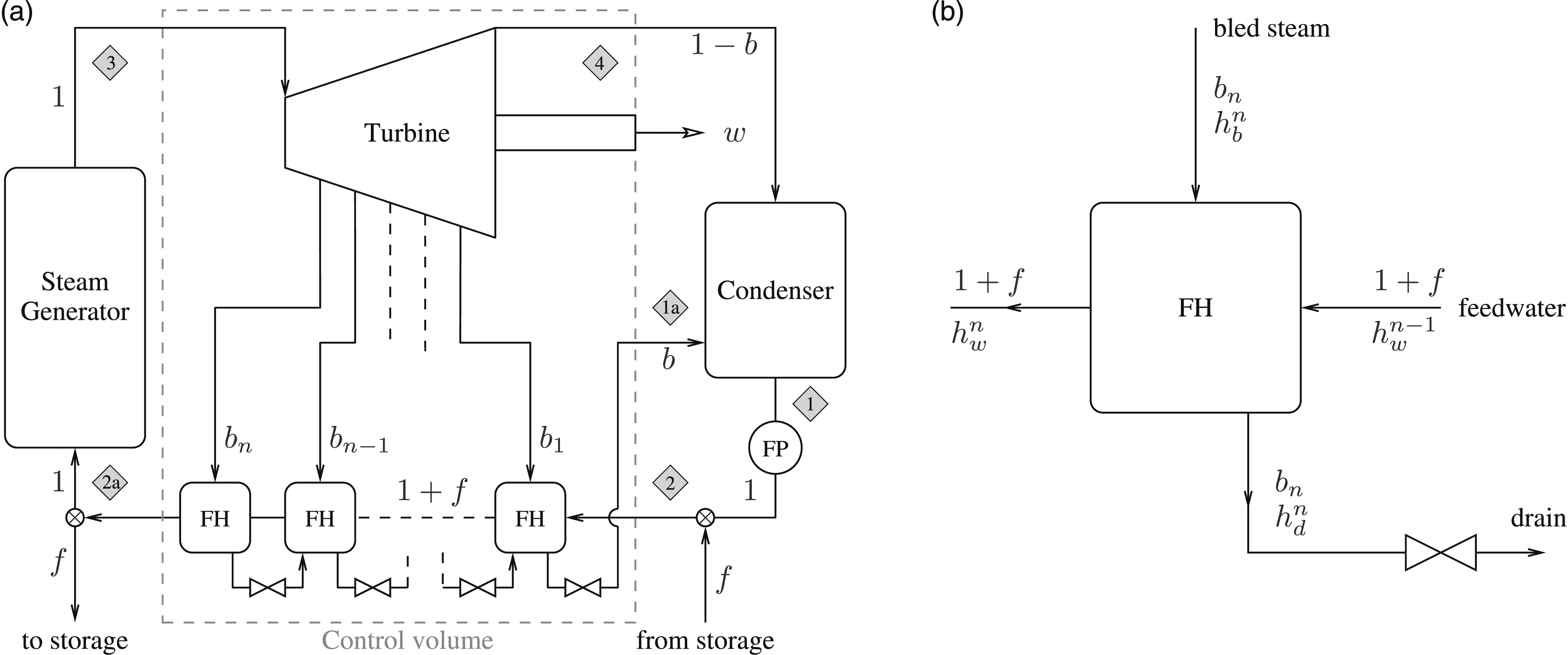
During the charge phase (as shown in Figure 1) the flow of water passing through the feedheaters is increased by a fraction f, such that the mass flow between states 2 and 2a is now 1 + f per kg of flow in the steam generator. This requires the steam bleed flows to be increased, thereby reducing the turbine work output. The additional fraction, f, of preheated feedwater is diverted to the thermal storage system and returned, after cooling, to rejoin the feedheat train at state point 2. The net effect is therefore that the work output from the plant decreases and thermal energy is transferred to storage. Possible options for how the thermal storage is implemented are described in the section, Thermal storage options; for now it is treated as an idealised ‘black box’ with no heat or exergetic losses. This means that the water returned from storage can rejoin the cycle after the feed pump and is at the same thermodynamic state as the feed pump delivery (i.e., state 2). The storage system is discharged by reducing the feedwater flow through the feedheating train and making up the deficit by water heated from the storage system, such that the flow rate through the steam generator is unchanged. The ‘excess feedwater fraction’ f is thus the key parameter determining operation of the storage, with positive values corresponding to charge and negative values to discharge.
Relation between work output and f
With the above assumptions, it is a straightforward matter to show that bleed flow rates, b
i
, scale as 1 + f. For example, application of the steady flow energy equation (SFEE) to the last (n-th) feedheater shown in Figure 1(b) gives


Applying the SFEE to the control volume in Figure 1(a), the work output from the turbine during charge (per kg of steam generator flow) is


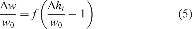
Subtracting equation (3) from equation (4) gives the decrement in turbine work output during charge, Δw = w0 − w, which (since the feed pump work is unchanged) is also equal to the decrement in net work output. After rearrangement, this may be expressed in the form
During discharge, the feedwater flow through the feedheat train is reduced below its design value, thereby requiring lower steam bleed rates and increasing the turbine work output. The deficit in preheated feedwater is made up by reversing the flow through the thermal storage system. The analysis leading to equation (5) remains valid, but this time with negative values of f such that Δw is now a work surplus.
Differences with real plant
In practice, the following factors will affect the performance of a real-life implementation of this form of storage: i. Real PWR plant requires a moisture separator and a reheater after the high-pressure turbine (HPT) to avoid excessive wetness in the low-pressure turbine (LPT). These additional components mean that the bleed flows no longer all scale uniformly with the water flow rate through the feedheat train. ii. Changes to bleed flows will result in the turbine and feedheaters operating off-design. This will usually lead to higher losses in these components. iii. Exergetic losses in the thermal stores mean that the make-up feedwater retrieved from storage during discharge will be cooler than the design feedwater temperature so that additional measures are required to keep conditions near their design values. Storage losses also impact upon the round-trip efficiency.
These matters and other practicalities are addressed in the sections below by means of standard cycle calculations applied to a typical PWR layout.
Detailed plant model
The cycle modelled here is representative of large-scale PWR plant and is based closely on the layout and operating conditions of Sizewell B station, as described in Ref 35. As shown in Figure 2, there are two turbines (the HPT and LPT), separated by a ‘steam-reconditioning’ system comprising a moisture separator and reheater. The feedwater heating train comprises seven closed (indirect contact) heat exchangers, with the feedwater at two different pressure levels. Condensed drain water from each feedheater is ‘cascaded’ down to the next, lower-pressure heater via a throttling valve. The storage system is shown in Figure 2 as a heat exchanger coupled to tanks of a thermal storage liquid but, as discussed in the Thermal storage options section, other methods could also be employed. Whichever means is chosen, it is possible to model the storage in a fairly generic manner by specifying an overall heat-exchange effectiveness. With the thermal storage system as shown, the throttle downstream of the heat exchanger is replaced by a pump during discharge. Plant layout showing thermal storage during charge. HPT = high pressure turbine; LPT = low pressure turbine(s); MS = moisture separator; RH = reheater; FH = feedheater; FP = feed pump; DA = deaerator; T = throttle; SP = (discharge) storage pump. The layout is based on the Sizewell B plant as described in Ref 35, but with minor simplification of the reheat system. Only the main components relevant to cycle calculations are shown.
Cycle calculations and assumptions
Steam conditions around the cycle and the schedule of bleed flows under normal operating conditions are tabulated in the appendix. The cycle analysis is standard and based on the following assumptions: i. All feedheaters are treated as shell-and-tube heat exchangers and are modelled using the NTU − ϵ approach, with specified UA values (i.e., overall heat transfer coefficient times interface area). This enables their off-design operation to be evaluated. ii. Turbines and feed pumps are assumed adiabatic and modelled with an isentropic efficiency. Bleed flow enthalpies are determined by applying the same isentropic efficiency between the turbine inlet and bleed pressures. Separate consideration is given to turbine off-design operation by means of throughflow calculations (see the Turbine off-design performance subsection). iii. The thermal storage is modelled as a balanced heat-exchange process. The value of heat exchanger effectiveness is chosen to reflect the exergetic losses in a realistic storage system.
The calculations are implemented in Python using the International Association for the Properties of Water and Steam (IAPWS) equation of state, 36 available via Refprop. 37 An iterative approach is required to fix conditions around the cycle for each value of f, full details of which are provided in the supplemental material.
System performance
Calculations were undertaken with the excess feedwater fraction, f, varied between −0.5 for the maximum discharge rate and +0.5 for the maximum charge rate. (Note that by comparison Margen 13 proposes turning off completely sections of the feedheat, but in practice the limits of variation for a given system would need to be determined.) Results are presented for a storage system in which the equivalent heat-exchange effectiveness is ϵ = 0.95 in each direction. This would be achievable if, for example, heat were transferred to tanks of thermal oil, as indicated in Figure 2. Exergetic losses in this heat-exchange process mean that the feedwater returned from storage is slightly cooler than its design value and (for the purposes of these calculations only) the deficit is made up by increasing the heat input in the steam generator. The changes are small but, in order to make fair comparisons, all work transfer (and similar) terms are rescaled by the corresponding exergetic input in the steam generator. (In practice, the feedwater temperature deficit might be rectified by, for example, a small bleed of live steam.)
The thermodynamic quantities of particular interest are the fractional change in net work output with f, changes in individual bleed flows and exergetic losses associated with off-design operation and with the transfer of energy to and from the stores.
First Law analysis
Figure 3(a) shows the main heat and work transfers to and from the steam cycle plotted against f. Note that all values are expressed as a fraction of steam generator heat input which remains close to its design value. The top line is the net heat input from the steam generator plus thermal storage and balances heat rejected via the condenser plus net work output. (Note that the feed pump and storage pump work have not been plotted separately as they never exceed 0.64% of the steam generator heat input, but they are included in wnet.) The heat rejected from the condenser increases during discharge (and decreases during charge) due to the increased steam flow leaving the LPT, in accord with the reduced bleed flows. This has implications for the operation of the condenser, as discussed in the Condenser operation section. Principal heat and work transfers as a function of f (a) normalised by steam generator heat input; (b) normalised by design value. Note that qin is the net heat input from both the steam generator and storage.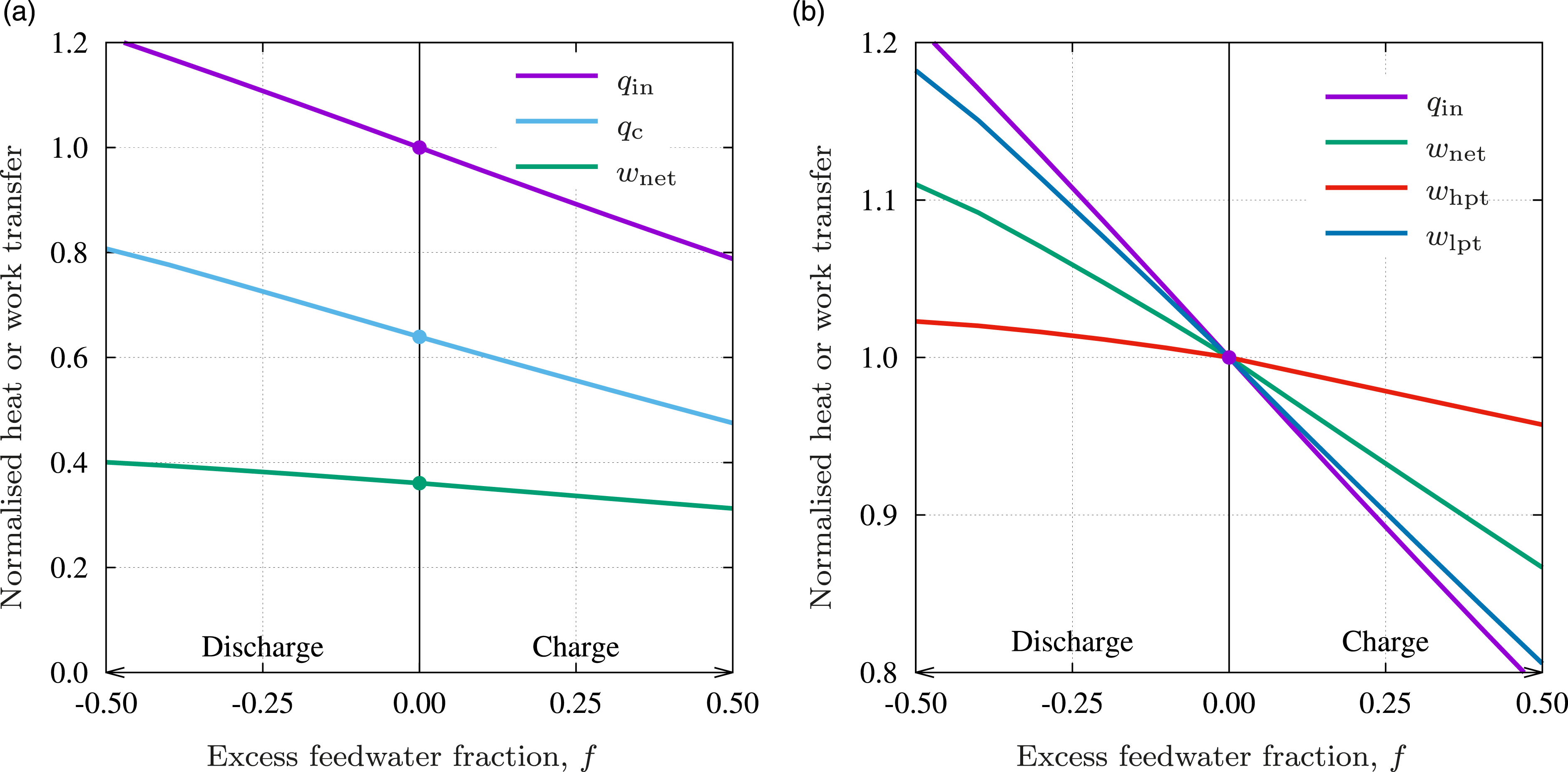
The net work output and individual contributions from the HPT and LPT are shown in Figure 3(b), with each quantity normalised by its design value. It is immediately apparent that the LPT output flexes much more than the HPT. This is because changes to bleed flows at high pressure clearly affect the main steam flow throughout the rest of the expansion and thus have a proportionately higher impact on work output – for example, during discharge, the LPT inlet flow is already significantly increased by virtue of reduced bleeds in the HPT. However, the differential changes in bleed flows tied to the operation of the moisture separation and reheat system also affect the division of work between the turbines, as described in the following subsection. The net work output increases by 10.2% at the maximum discharge rate (i.e., 0.204% for each 1% reduction in feedwater flow) whereas it decreases by 12.3% at the maximum charge rate (0.246% per 1% feedwater flow). These figures compare with 0.28% work increase/decrease per 1% feedwater flow change from the Simplified analysis section, the discrepancies arising from a combination of additional exergetic losses and non-uniform changes to bleed rates.
Analysis of feedheat and bleed flows
As noted, using the feedheat train to transfer heat to storage automatically ensures good thermal matching between the (principally) ‘latent’ heat of the steam and ‘sensible’ heat of the storage medium. This is illustrated in the T-Q diagram (Figure 4) which shows how the ‘staircase’ of bled steam lies close to the feedwater temperature profile, thereby enabling heat to be transferred with relatively little irreversibility. (Note that transferring this heat onward to the storage medium can also be achieved efficiently by matching the heat capacities of the main heat exchanger streams.) This is in contrast to many of the storage systems described in the Recent work subsection, which extract heat directly from the supply steam and must therefore either be coupled with PCMs or suffer large exergetic losses if used with sensible heat storage. T-Q plot for the feedheating train showing the close proximity of bled steam and feedwater profiles.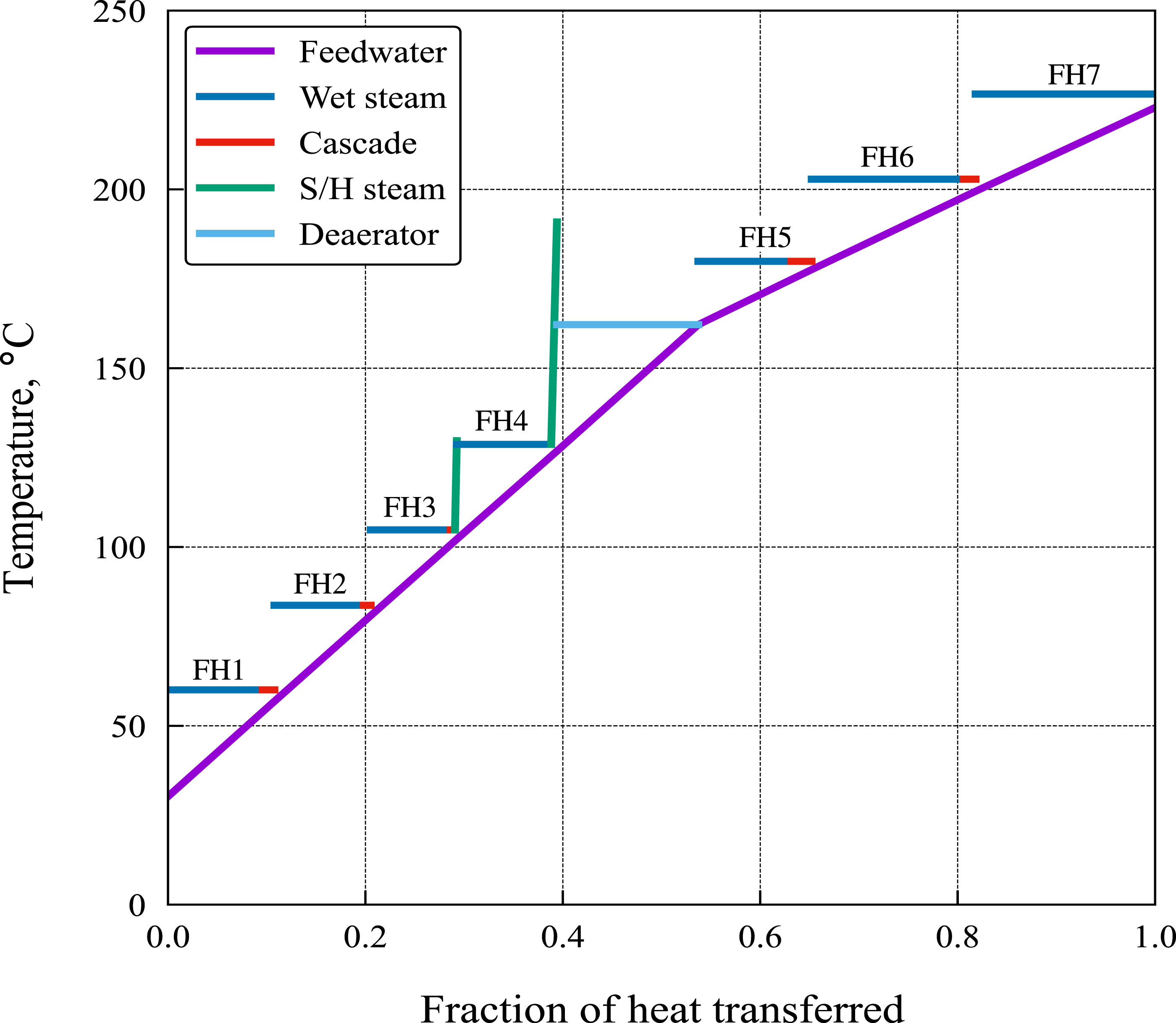
Figure 5 shows how the operation of the various feedheaters change as f is varied. (Only alternate heaters are shown to avoid overcrowding.) Recall that under the assumptions of the simplified analysis presented above the feedwater temperature rise through each feedheater would remain constant and the corresponding bleed flow would scale as 1 + f. This is almost exactly true for FH7 and is approximately true for most other feedheaters, but notable exceptions are FH1 and FH5. Operation of alternate feedheaters: (a) feedwater temperature rises; (b) bleed flow rates; (c) turbine and reheater flow rates; (d) NTU and feedwater flow rates. All quantities in (b–d) are normalised by their design (f = 0) values.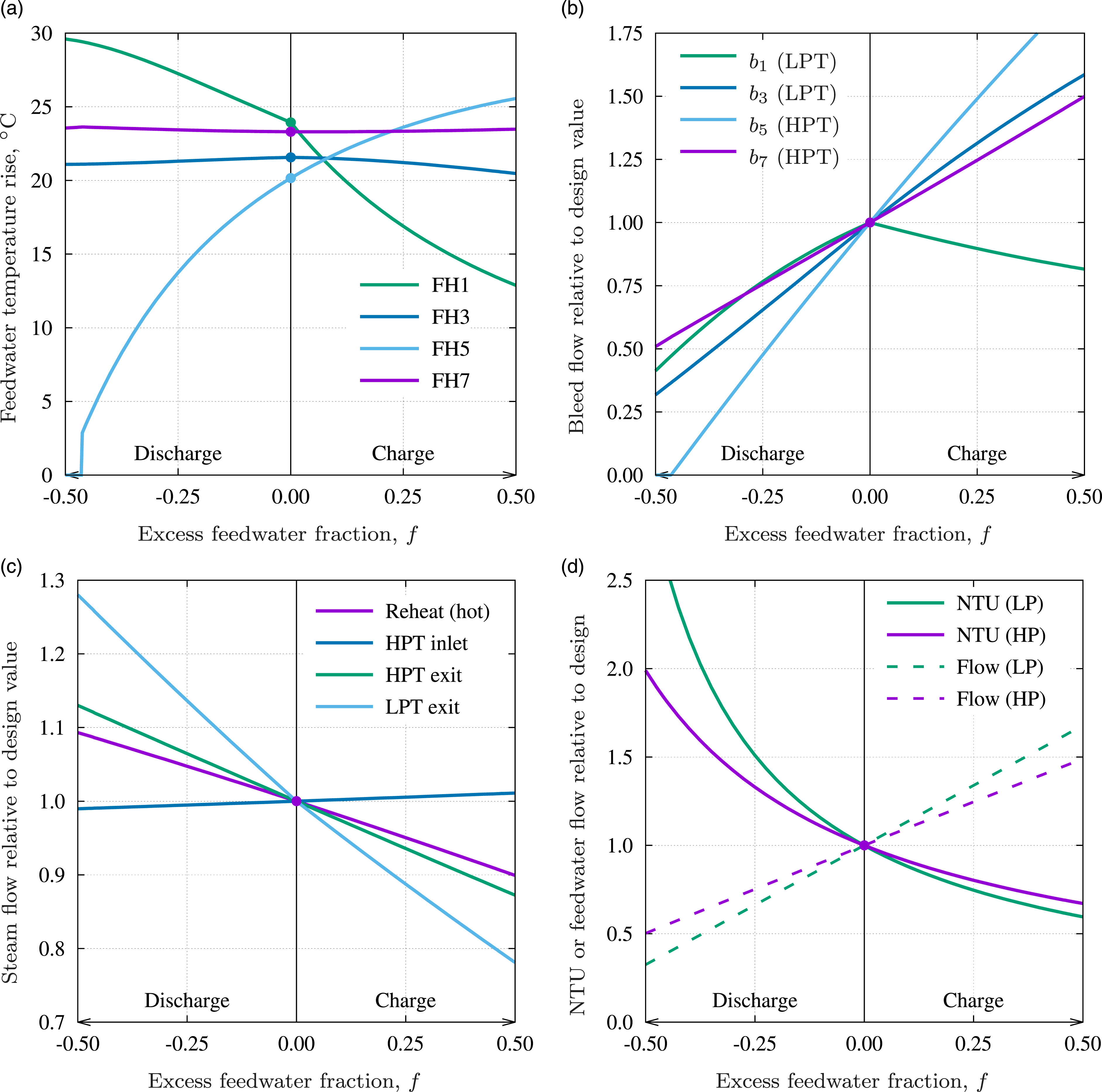
During charge FH1 is affected by the temperature of water returning from the storage system which, due to imperfect heat transfer with the storage fluid, is hotter than the condenser water. For example, with the assumed storage-system heat transfer effectiveness of 0.95 (representative of liquid-tank storage) the return temperature at f = 0.50 is around 55°C, compared with 46°C from the condenser extraction pump, FP1. After mixing, the inlet to FH1 is thus warmer than at design such that the required temperature rise decreases with f (Figure 5(a)) and b1 actually decreases with f during charge (see Figure 5(b)).
The fifth feedheater lies after the deaerator which, aside from removing air from the feedwater, serves to re-integrate the water drained from the moisture separator and reheater. As f is reduced during discharge the HPT exit flow increases since less steam is bled from the turbine. The fraction of live steam diverted to the reheater must therefore also increase (Figure 5(c)) in order to maintain the superheat at the LPT inlet. The flows of hot water to the deaerator from the moisture separator and reheater thus both increase, thereby increasing the feedwater temperature at inlet to FH5. Eventually (when f ≃ − 0.45) this temperature exceeds that of the corresponding bled steam such that b5 falls to zero.
Aside from the above, purely thermodynamic considerations, the operation of the feedheaters is also affected by departures from their design mass flow rates. This is accounted for here by scaling the NTU values for each feedheater inversely with the feedwater flow rate, assuming that UA values remain unchanged. (In practice, heat transfer coefficients will increase with flow rate such that departures from the design point will be less than suggested by this analysis.) With the exception of FH3 and FH4, the bled steam flows are all in the two-phase (wet) region, and their temperatures thus remain constant at the appropriate saturation value. For these cases the ϵ − NTU relationship takes the form


Second law analysis and efficiency
The thermodynamic performance of stand-alone (EIEO) storage systems is usually quantified by the round-trip efficiency, ηRT, defined as the electrical energy retrieved during discharge divided by that transferred to storage during charge. For GIES systems a slightly different definition is required, namely
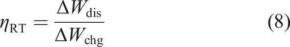
Contours of round-trip efficiency calculated from equation (9) are shown in Figure 6(a). These suggest that it is more efficient to charge rapidly and discharge slowly than vice versa, which, unfortunately, is probably the opposite of what is desirable. However, the round-trip efficiency is high (compared to stand-alone thermo-mechanical storage systems) due to the fact that many of the exergetic losses involved would have occurred anyway during the normal course of generation. This feature of GIES is highlighted by splitting ηRT into charge, storage and discharge components as follows: Thermodynamic efficiency: (a) round-trip efficiency contours as a function of excess/deficit feedwater fractions; (b) components of efficiency for cases where f
d
= −f
c
(i.e., equal charge and discharge rates).
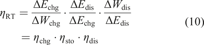
Figure 6(b) shows the variation of the above efficiency components with |f| for cases where the charge and discharge rates are equal (i.e., fdis = −fchg). It is particularly notable that ηchg > 1 throughout – i.e., the exergy transferred to storage exceeds the deficit in work output. This is clearly not possible for EIEO storage and is best understood by considering how the distribution of ‘lost work’ changes between, charge, normal operation and discharge, as shown in Figure 7. (Note that losses due to irreversibility are computed from the relevant T0Δsirr terms, whereas in the condenser the lost work is the reduction in availability (b = h − T0s) of the condensing steam.) Cycle losses are dominated by turbomachinery lost work which falls during charge due to the reduced flow through the turbines. Likewise, the condenser, reheat and moisture separation losses also fall for the same reason. By contrast, the feedheat loss increases substantially, partly due to the increased flows through the feedheaters and partly because these devices operate off-design and with lower effectiveness, as described above. The net effect is that exergetic losses fall during charge such that the exergy transferred to storage exceeds the reduction in work output, as observed in the first and third bars on the left of Figure 7. During discharge the opposite trends occur such that ηdis < 1. It is interesting to note, however, that ηdis remains significantly above the rational efficiency of the nominal cycle (η
R
≃ 0.78) – in other words, the exergy transferred to the cycle from storage is converted to surplus work with a second-law (exergetic) efficiency greater than that of the cycle itself. This is desirable as it helps maintain a high energy-storage density. Cycle losses during charge (f = 0.5), normal operation (f = 0) and discharge (f = −0.5).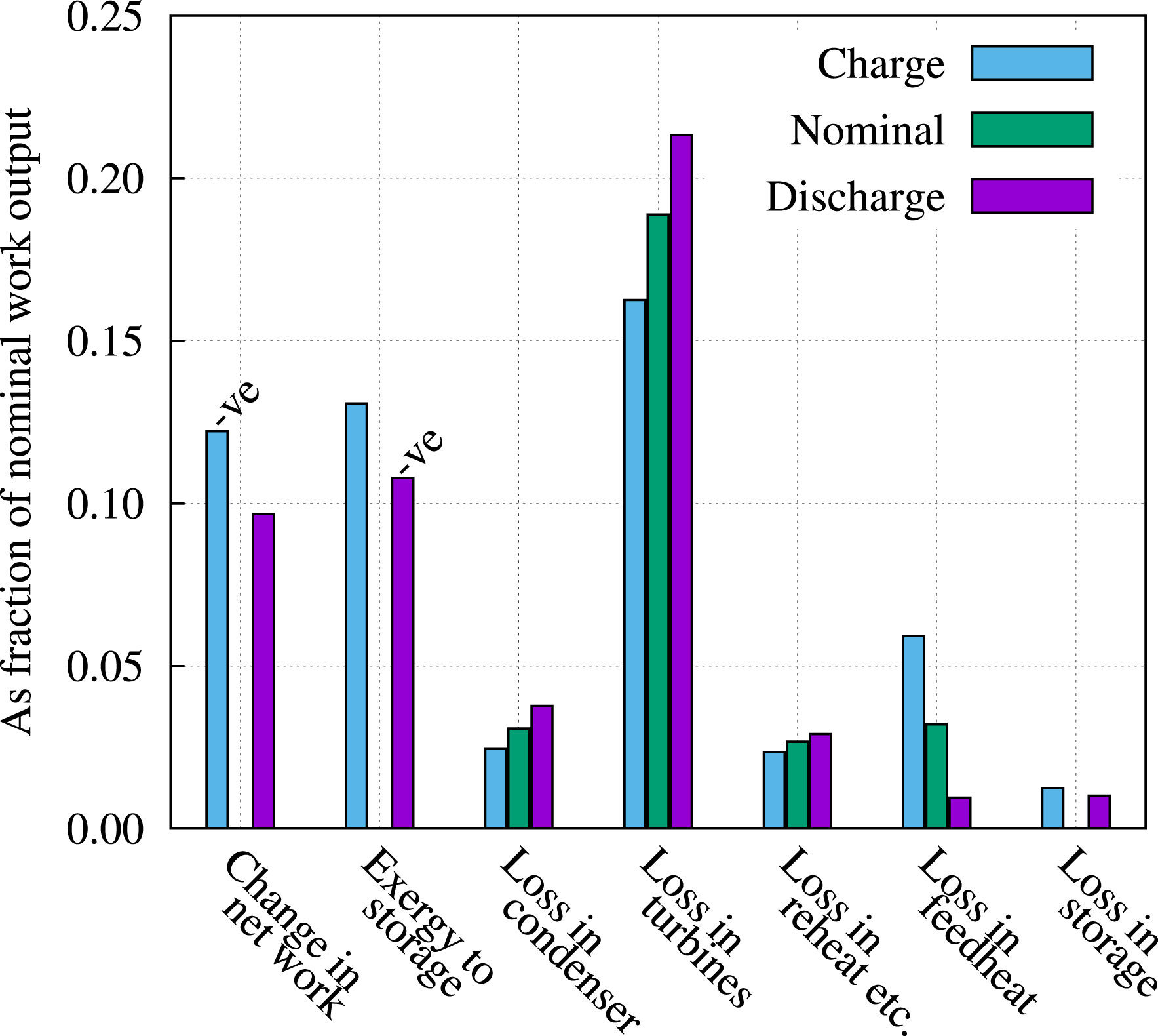
Thermal storage options
The energy stored per unit volume of surplus feedwater (as given by ρ w Δwdis/|fdis|) is roughly 30 kWhe/m3. This is a relatively high energy density for thermo-mechanical systems, exceeding that of typical compressed-air and pumped-hydro energy storage by factors of three and thirty respectively. However, the actual storage density achieved (and indeed the cost per kWhe capacity) will depend on the final storage medium. Three alternatives are considered here:
Indirect liquid-tank storage
This is the method depicted in Figure 2 and entails transferring heat from the surplus feedwater to a suitable storage fluid that can be stored in ambient-pressure tanks. Candidate fluids include mineral oils, natural oils (e.g., sunflower oil) and other synthetic heat transfer fluids such as ‘Therminol VP-1’. A discussion of the cost, exergy density and suitability of such fluids for thermal storage is given by Farres-Antunez. 38 Typically, energy densities are significantly less than that of water – e.g., accounting for discharge losses, the storage density of VP-1 at 220°C is about 14 kWhe/m3, so to store 10% of the output from a 1 GW plant for a day would require roughly 175,000 m3 (e.g., 28 tanks of 20 m diameter by 20 m high). The cost of VP-1 lies in the range 0.4 to 2.6 £/kg 39 giving a contribution to capital cost from the storage fluid alone in the range 25 to 155 £/kWhe capacity. The upper end of this range is probably not viable. Vegetable oils are much cheaper (typically less than 10 £/kWhe) but their durability under cyclic heat load is unproven and they pose a potential fire risk.
Direct pressurised water storage
The simplest solution is to store the feedwater directly, as shown in Figure 8(a). This avoids the need for an additional heat exchanger but the storage vessels need to be pressurised. Overall costs can be reduced by employing a single-tank system containing a natural ‘thermocline’ or a piston-like insulated separator between the hot and cold water (as shown) that prevents mixing. (Note, a US patent
40
for a similar device was filed in 1985.) In fact, the storage temperature of around 220°C lies close to the value that minimises the total cost per unit exergy, estimates for which are in the range 25–35 £/kWhe.
41
(The value estimated by Margen et al.
13
lies within this range once corrected for inflation.) Judging this too expensive, Margen et al. proposed the use of excavated underground cavities, for which they claimed an almost four-fold reduction in cost relative to steel pressure vessels.
13
Alternative forms of thermal storage: (a) direct pressurised storage; (b) multiple packed-bed storage. SP = storage pump (discharge), T = throttle, CV = control valve, MHX = main heat exchanger, CP = circulating pump. Arrow directions are for charge.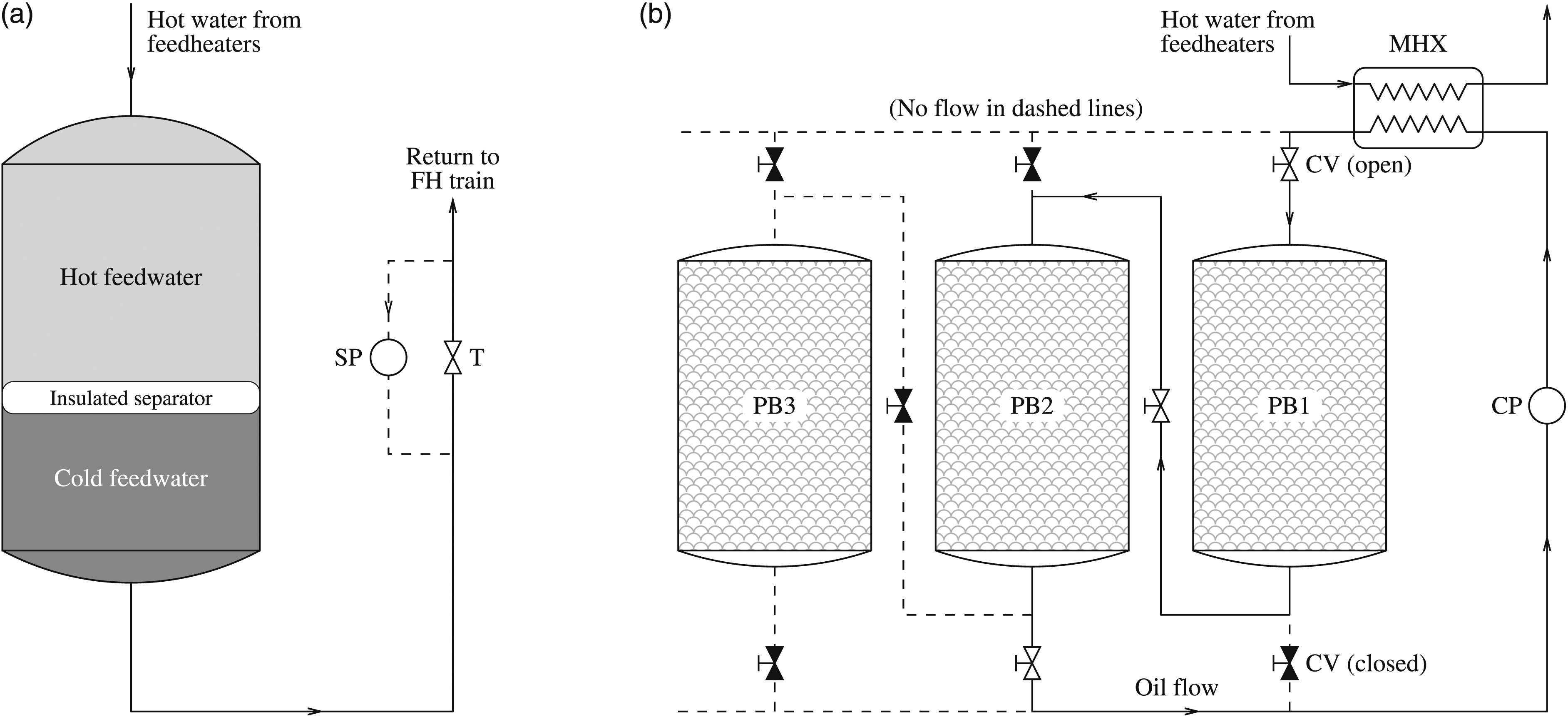
Multiple packed-bed storage
Figure 8(b) shows an alternative means of avoiding pressurised stores wherein heat is first transferred to an intermediate heat transfer fluid (e.g., mineral oil), and then onwards to a series of packed beds. The volumetric heat capacity of suitable storage media such as magnetite is comparable to that of water, 42 but accounting for voidage reduces the effective storage density by about 40%. The use of multiple beds means that only enough oil to fill the voids in two or three beds is required (out of perhaps 40 or 50), thereby reducing cost considerably. It also enables a higher exergetic efficiency since pressure losses are confined to ‘active’ beds that contain the thermal front. (See Ref 43 where it is shown that packed-bed charge-to-discharge exergetic efficiencies above 95% can be attained even with a gaseous heat transfer fluid.) In practice the thermal front may straddle two packed beds at any one time – thus, for example, the arrangement of valves in the figure is such that the oil passes through PB1 and PB2 in series before returning to the main heat exchanger. Preliminary estimates of cost for multiple packed-bed systems suggest values in the range 25–35 £/kWhe. 41
Practical considerations
Turbine off-design performance
Changes to bleed flows will clearly have an effect on the aerodynamic performance of the turbines and it is therefore important to establish that any ‘off-design’ deterioration in efficiency, particularly during discharge, does not outweigh the increased work output accruing from reduced steam extraction. This can only be properly ascertained by carrying out tests on real plant, but such tests would be difficult to undertake in practice as any adjustment to bleed flows would necessarily affect the feedheat train, thereby also changing thermodynamic aspects of the plant. As a preliminary assessment of how overall turbine performance is affected, throughflow calculations have been undertaken on a representative LP turbine geometry using Denton’s streamline curvature method. 44 This method is particularly aimed at predicting steam-turbine flows and is able to cope with the fully-choked and partially-choked stages that often occur in LP turbines.
The geometry used for the throughflow calculations is that of a real LP turbine from a fossil-fired plant (the now-dismantled Kingsnorth power station) as data for the Sizewell B turbines were not available. (As noted by Hesketh,
35
the Sizewell plant was designed to make use of conventional LP turbines, so this geometry is nonetheless relevant to PWRs.) Full details of the streamline equilibrium (SLEQ) calculations are given in the supplemental material, including detailed changes to blade incidence angles with varying bleed flows and corresponding changes to local loss coefficients. At the design mass flow and bleed schedule the last turbine stage is partially choked, and a greater fraction of the stream tubes become choked when bleed flows are reduced, as expected. Figure 9(a) shows the changes to the third and fourth rotor blade incidence angles as the bleed flows are adjusted. A reduction in the bleed flows (e.g., the curve b/b0 = 0.3, for which all bleed flows are reduced by 70%) corresponds to an increase in axial velocity through the latter stages of the machine, which in turn leads to increased flow angles in the rotor relative frame, particularly near the casing. (Rotor 3 shows greater variations than rotor 4, chiefly because the relative flow is closer to the axial direction in rotor 3.) The changes are not, however, sufficient to cause a significant increase in aerodynamic loss, so the predicted isentropic efficiency remains close to its design value, as shown in Figure 9(b). This figure also compares the work output predicted by the cycle calculations (labelled GIES model) with that from the SLEQ calculations. Note that the LPT inlet mass flow has been maintained at its design value in the SLEQ calculations, whereas in the GIES model this mass flow varies by virtue of changes to the HPT bleed schedule (see Figure 5(c)). The GIES results have accordingly been normalised by the inlet mass flow, and in this normalised form agree well with the SLEQ calculations. (Discrepancies at high bleed rates – i.e., during charge – are due to the non-uniform changes to different bleed flows as described in the Analysis of feedheat and bleed flows subsection) The figure also includes results for a second machine (the five-stage LP test turbine described by Kreitmeier et al.
45
) indicating that the findings are not sensitive to geometry. (a) Changes to LP turbine rotor 3 and 4 incidence angles predicted by Denton’s throughflow method (SLEQ).
44
(b) LP turbine efficiency and work output predicted by SLEQ, and comparison with cycle calculations (GIES). The GIES work o/p has been normalised by the LPT mass flow rate at inlet. The abscissa is numerically similar to 1 + f. Solid symbols are for the Kingsnorth turbine, open symbols are for the turbine described in Ref 45. The design point isentropic efficiency is 0.84.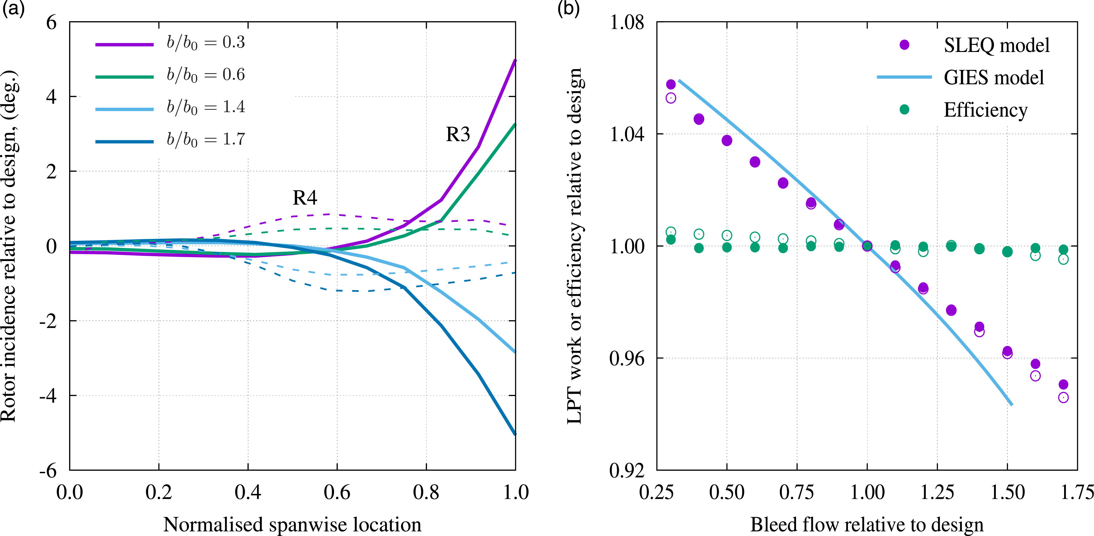
Streamline curvature calculations cannot capture all the complex phenomena associated with changes to bleed flows, but the above results nonetheless suggest that some flexing of the turbine output might be accomplished without significant deterioration in performance. However, large increases in LP inlet mass flow (due to reduced bleed in the HPT) are likely to fully choke the last stage for many turbines. In such cases, a larger capacity LP turbine needs to be selected at the design stage.
Condenser operation
It has been assumed in the cycle calculations presented herein that the condenser vacuum remains constant irrespective of whether the plant is operating in charge, discharge or normal mode. However, at the maximum discharge rate considered (f = −0.5) the condenser steam flow rate increases by roughly 28%. It is possible to increase the cooling water (CW) flow rate to match this, but maintaining the same condenser pressure requires an even greater increase in this flow rate due to the reduction in effectiveness that occurs with higher water mass flows.
The required cooling water flow can be estimated by the following straightforward analysis. Firstly, application of the SFEE to the condenser (for arbitrary f) gives


Figure 10 shows CW flow rates based on equation (13) as a function of steam flow rate for different values of design effectiveness, ϵ0. A perusal of the literature suggests ϵ0 would be in the region of 0.8, such that increases in CW flow in excess of 50% would be required at the maximum discharge condition if the condenser pressure is to be maintained. In practice it may be expedient to design for a larger condenser (and hence higher ϵ0) whilst also allowing the condenser pressure to rise slightly, thereby sacrificing some of the surplus work Δwdis. Cooling water flows required to maintain condenser vacuum for different values of design effectiveness, ϵ0.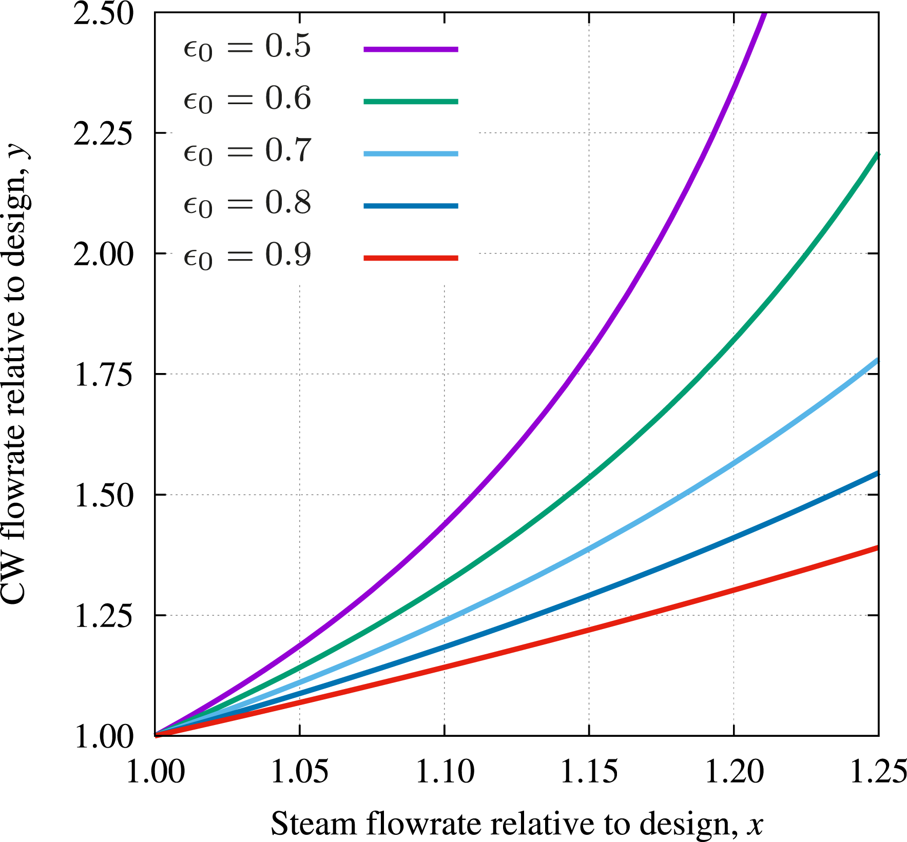
Feedwater deaeration
As shown in Figure 2, the fraction of feedwater heated by the storage system during discharge bypasses the deaerator. This may lead to unacceptable levels of dissolved oxygen and thus require some separate means of deaeration. One possibility is to split the main (storage) heat exchanger into two sections, returning the (additional) feedwater to the main deaerator between the two. In principle this has only minimal impact on thermodynamic behaviour, but would add to complexity and cost.
Certification
Nuclear power plants are heavily regulated and require complex and lengthy licensing processes before construction. The proposed power cycle modification will inevitably impact this process, requiring comprehensive justifications for safety implications. On the positive side, the addition of storage will increase the thermal inertia of the secondary circuit, smoothing out power transients and reducing thermal stress and fatigue on the steam generators. It will also reduce thermal cycling of all the core components, which can potentially relax some of the design constraints and prolong the lifetime of steam generators and the primary system. However, the proposed system would also introduce new potential for faults which may require additional protective measures. The assessment of the complexities and costs of these, both in terms of hardware and regulatory burden, are beyond the scope of this study, but will be considered in future work.
Conclusions
A detailed thermodynamic analysis has been presented for an electricity storage system in which thermal stores are integrated into the feedwater heating system of nuclear plant. This enables exergetically efficient transfer of the (principally latent) heat from the steam to storage and allows existing power-conversion hardware to be exploited. The analysis takes account of the off-design operation of feedheaters within the cycle calculations, whereas off-design operation of the condenser and turbine are considered separately, the latter by means of an established throughflow calculation method. The following conclusions emerge: i. A simplified control-volume analysis shows a straightforward relationship between the fractional decrease (or increase) in power output and the fractional change in feedwater flow, diverted to (or returned from) storage. This relationship depends only on the nominal turbine work output and the enthalpy drop across the turbines, typical values for which give roughly a 0.3% change in work output for each 1% change in feedwater generated. ii. Taking account of exergetic losses associated with heat transfer to and from storage, and the non-uniform operation of the feedheaters due to moisture separation and reheat, results in the above figure falling to about 0.20% (discharge) and 0.25% (charge) for each 1% change in feedwater. Furthermore, depending on the required balance between power and energy capacity of the storage system, it may be beneficial to exploit only the HP feedheat train, which would further affect this figure. iii. The cycle calculations suggest that an effective round-trip efficiency of around 80% can be achieved. This is relatively high for a thermo-mechanical storage system and reflects the fact that heat storage occurs prior to conversion to electricity so that exergetic losses that would occur anyway are simply deferred. This point is emphasised by the real possibility that the exergy transferred to storage can exceed the deficit in electrical work output, leading to an apparent charge efficiency greater than 100%. iv. Off-design analysis of the feedheaters (based on a conservative NTU − ϵ model) suggests that departures from normal design conditions have only a small impact on their operation and hence on the performance of the storage system as a whole. v. Achieving a significant (e.g., 10%) increase in power output results in a substantial (around 30%) increase in steam flow through the condenser, which would probably, therefore, need resizing. This is necessary to avoid an upward drift in condenser pressure that would offset the increase in power output. (Further analysis of how this might affect system performance is the subject of ongoing work.) vi. Throughflow calculations applied to a representative LP turbine suggest that modest changes to bleed flows can be accommodated without significant impact on the turbine efficiency. However, the substantive increase in LP turbine inlet flow (stemming from reduced HP bleed rates) is likely to require increased swallowing capacity of the LP turbine, depending on the required extent of power flexing and on the designed ‘over-capacity’ of the existing turbine. vii. Preliminary estimates indicate that it should be possible to achieve costs in the tens-of-pounds-Sterling range per kWhe storage capacity.
Further work will include optimisation of storage integrated with future designs of SMR plant and more detailed analysis of costs, both per KW and per kWh capacity.
Supplemental Material
Supplemental Material - A feedheat-integrated energy storage system for nuclear-powered steam plant
Supplemental Material for A feedheat-integrated energy storage system for nuclear-powered steam plant by James W Lazenby, Eugene Shwageraus and Alexander J White in Proceedings of the Institution of Mechanical Engineers, Part A
Footnotes
Declaration of conflicting interests
The author(s) declared no potential conflicts of interest with respect to the research, authorship, and/or publication of this article.
Funding
The author(s) disclosed receipt of the following financial support for the research, authorship, and/or publication of this article: The first author is grateful to the Harding Distinguished Postgraduate Scholars Programme Leverage Scheme for a partial research studentship. All authors gratefully acknowledge support from the EPSRC under the GIES project EP/P021867/1.
Supplemental Material
Supplemental material for this article is available online.
Appendix
References
Supplementary Material
Please find the following supplemental material available below.
For Open Access articles published under a Creative Commons License, all supplemental material carries the same license as the article it is associated with.
For non-Open Access articles published, all supplemental material carries a non-exclusive license, and permission requests for re-use of supplemental material or any part of supplemental material shall be sent directly to the copyright owner as specified in the copyright notice associated with the article.