
Abstract
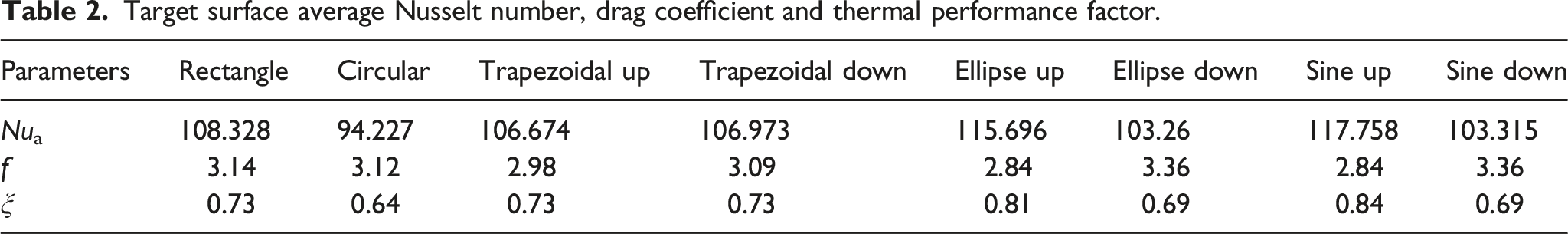
In this paper, according to the actual size of gas turbine blade interior space, eight vortex cooling models with different cross-sectional shapes of coolant chambers are established. Rectangular, Circle, Trapezoidal up, Trapezoidal down, Ellipse up, Ellipse down, Sine up and Sine down are the eight coolant chamber shapes. Functions of variable coolant chamber structures on vortex cooling flow and heat exchange characteristics are numerically analyzed by verifying the Standard k-ω turbulence model and conducting grid independence analysis. Research results show that the heat exchange ability of Sine up coolant chamber is the best compared with the other coolant chambers. The cool air enters the vortex chamber at a faster speed and impacts on the target surface to form a high-pressure area and a low-temperature swirl. The more the cool air moves downstream, the greater the turbulent kinetic energy becomes, which is more conducive to the heat transfer. Therefore, Sine up coolant chambers have the highest thermal performance factor. Due to the low drag coefficient and high target surface average Nusselt number of Ellipse up, its thermal exchange performance is second only to that of Sine up. Circle coolant chamber will not bring favorable factors to engineering application because of the slowest flow speed and the worst heat exchange capacity. For Trapezoidal up and Trapezoidal down, the flow velocity, pressure distribution, turbulent kinetic energy intensity and heat transfer uniformity are almost the same as Rectangle coolant chamber. The models of Ellipse down and Sine down coolant chambers exhibit less turbulent kinetic energy strength to heat transfer and higher temperature in the vortex chamber, and it is not suggested for cooling system optimal design.
Introduction
Gas turbine is important high-speed rotary power mechanical equipment which uses air and gas as combustion medium to convert fuel chemical energy into mechanical energy. Brayton cycle shows that increasing the inlet gas temperature can effectively improve the thermal efficiency for gas turbines. For the moment, the inlet gas temperature of the turbine can reach nearly 1700°C. Obviously, this temperature has been far beyond the thermal limit of the blade material, especially at the blade leading edge. Therefore, it is necessary to take a series of protection measures for the blades from thermal erosion. The main method is improving the performance of blade cooling system to availably resist the corrosion for inlet gas on blade leading edge. Vortex cooling is a typical internal cooling mode to protect the blades from high temperature. Compared with impingement cooling, vortex cooling has the better cooling capacity and uniform heat exchange distribution, which have become a frontier topic in the research of gas turbine blade leading edge cooling.
Lots of scholars have studied the structure of vortex cooling, including the geometric parameter of vortex chamber, new cooling structures and adding a coolant chamber to the basic semi-circular vortex chamber. The early research mainly focused on the change for the geometric parameters of the vortex chamber. Dhir and Chang 1 found that the pipe diameter and nozzle size of the cyclone chamber had a weak effect on the improvement of thermal exchange property in swirl cooling through experimental results. Biegger et al. 2 used PIV flow field and transient liquid crystal temperature display technology to explore the thermal transfer distribution characteristics of the outlet structure for the straight channel, tangential channel and 180° elbow. Du et al.3,4 numerically investigated the effect of the nozzle angle, nozzle aspect ratio, nozzle number and nozzle geometrical shape on flow and thermal exchange performance of swirl cooling by solving the 3-D steady RANS equations. They observed that the swirling motion of cool air was weakened and the heat exchange intensity was reduced when the jet angle is far away from 90°. When the aspect ratio of the nozzle increases from 0.2 to 9, the cool air turbulent kinetic energy firstly decreased and then increased. As the number of nozzles increased, the cool air injection velocity decreased. Wang et al. 5 described the comprehensive thermal coefficient and heat exchange ability under variable cross-section of vortex chamber with the different vortex chamber draft angle β. The results showed that the change of the β had a great influence on thermal exchange, and the increase of the β directly led to the decrease of the cool air static pressure.
In addition to the simple circular tube vortex cooling chamber structure, a number of new vortex cooling structures have been developed. Kusterer et al. 6 took the lead in planning the double-swirl cooling structure. The swirl chamber was composed of two circular tubes and nozzles in the tangential direction, so that the cool air would generate swirling pairs with opposite rotating directions in the two chambers. Based on the simulation method of Du et al.,3,4 Fan et al. 7 established a vortex cooling model with film holes and numerically studied the peculiarities of geometric parameters such as film hole angle and diameter on blade leading edge. Lin et al. 8 proposed a double vortex chamber by combining two standard vortex chambers and showed the influencing factors of vortex cooling behavior, such as the merging ratio of the chamber and other geometric parameters. Fan et al. 9 developed a new type of vortex double-wall cooling structure. In addition, it was verified that variable cooling methods combined with double-wall cooling, variable disturbing objects added to the outer surface, different rows of bridge holes and the existence of cooling holes had significant changes on the vortex cooling power. Wassermann et al. 10 conducted an experiment to investigate the impacts of different vortex chamber outlet shapes on the thermal transfer intensity. Based on the double-swirl cooling structure, Zhou et al. 11 explored the thermal exchange and flow operations under different film hole angles and diameters. The heat transfer capacity of three groups for film cooling hole rows were compared. Yang et al. 12 carried out numerical studies on the cooling parameters of the new-type film holes (bean-shaped holes) in turbine end walls. By comparing the variable hole outlet shapes with the traditional round hole, it is noteworthy that the bean-shaped hole has the better cooling conditions. Jing et al. 13 adopted a new cyclone cooling method with multi exit slots, for which different outlet configurations are considered. At the same time, dimples/protrusions were introduced into the cyclone chamber in various arrangements for comparative analysis. Seyed et al. 14 analyzed five different inlet configurations based on the vortex chamber and double vortex chamber. They pointed out that if the direction of inlet slots was reasonable, strong vortices would be generated to increase Nusselt number.
Besides, most of the vortex cooling devices allow for space inside the blade and the calculation model has a coolant chamber. Fan et al. 15 introduced the coolant chamber structure to compare the flow and thermal exchange performances of impingement cooling, vortex cooling, intermediate double vortex cooling and tangential double vortex cooling under same boundary conditions, inlet chamber size and vortex chamber volume. It could be found that vortex cooling has the best heat exchange intensity, but tangential double vortex cooling had the worst heat transfer features. Fan et al. 16 established a semi-circle vortex cooling model with five nozzles and a coolant chamber. By combining experiment and simulation, the thermal transfer coefficient and streamline distribution were gained. Wu et al. 17 designed a vortex and impingement composite cooling model with a coolant chamber by arranging different vortex and impingement nozzles, and systematically researched the comprehensive property of four vortex and impingement composite cooling structures. Li et al.18,19 demonstrated the heat fluid-structure coupling method to testify the flow and thermal exchange homogeneities of solid region, and presented a coolant chamber to study the stress and displacement distributions of solid region, and made an impact on different swirl chamber curvature and height on vortex cooling. Wang et al. 20 presented the swirl and film composite cooling model combined with the actual mainstream and a coolant chamber, and arranged the coolant nozzles on the pressure side and the suction side respectively for comparison.
From the above discussion, it can be observed that the introduce of coolant chamber has important research significance for the flow and thermal transfer characteristics of vortex cooling. At present, most of the coolant chamber structure is rectangular. However, the vortex nozzle coolant distribution and flow behavior for the rectangular coolant chamber may not exhibit the optimal performance. When the shape of the coolant chamber is changed in a reasonable available space inside the blade, the cool air distribution and flow behavior of different vortex nozzles will also change, thus affecting the overall cooling functions of the blade leading edge vortex cooling structures. On this way, it is necessary to change the cross-sectional shapes of the coolant chamber to effectively overcome the shortcomings in the traditional rectangular coolant chamber. Therefore, it is of great industrial and scientific value to select the appropriate shape for the cross-sectional area in the vortex cooling coolant chamber.
In this paper, eight coolant chamber models with different cross-sectional shapes based on vortex cooling are developed. At the same time, the vortex cooling flow and heat exchange features are analyzed to research the interaction between the coolant chamber and the vortex chamber, which makes the vortex cooling procedure more closed to actual working conditions. Furthermore, this study seeks to get an appropriate cross-sectional shape of the coolant chamber and provides a reference for better structural design in vortex cooling model.
Numerical method
Geometrical details
Figure 1 shows the structure diagram of the three-dimensional model in vortex cooling structure. The whole vortex cooling calculation model is located at the leading edge of the gas turbine blade. The vortex cooling configurations consists of coolant chamber with variable cross-sectional shapes, vortex nozzles with tangential arrangement and vortex chamber. Cool air enters from the coolant chamber through six rectangular nozzles into the vortex chamber, forms a high-speed rotating motion and finally exits from the outlet. This paper is a theoretical and regular scientific exploration, and the purpose of the research is to discover the effect of variable coolant chamber structures on the vortex cooling function. In order to highlight the divergence in the shape of different coolant chambers without affecting the judgment of engineering, eight cross-sectional shapes of coolant chambers are selected to make the conclusion more comparative. To make it easier to discuss the simulation results, Rectangular, Circular, Trapezoidal up, Trapezoidal down, Ellipse up, Ellipse down, Sine up and Sine down are adopted to investigate the influences of their shapes on vortex cooling flow and thermal exchange characteristics. The two-dimensional view of vortex cooling is shown in Figures 2 and 3. Among them, considering the actual size of the blade space, the volume and axial length of the coolant chamber should be the same, so the model is built with the same cross-sectional area but different shapes. Therefore, based on the rectangular cross-sectional area size of 9 mm × 15 mm, the cross-sectional area of the other shapes is about 135 mm2. The Z coordinate represents the direction of the cool air flow into the coolant chamber, and then the plane parallel to the inlet section is established as the XY section. Three-dimensional view of vortex cooling. (a) Schematic view of vortex chamber geometry for blade leading edge. (b) Schematic diagram of vortex cooling model. Geometrical dimensions of eight structures in YZ section. Unit: mm. Two-dimensional views of eight configurations. Unit: mm. (a) Rectangular. (b) Circle. (c) Trapezoidal up. (d) Trapezoidal down. (e) Ellipse up. (f) Ellipse down. (g) Sine up. (h) Sine down.
Parameter definition
The inlet Reynolds number for coolant chamber is defined as follows:

Static pressure coefficient is used to represent pressure distribution:

Nusselt number is used to appraise the thermal transfer property:

The velocity component Vxy in the x and y directions are defined:
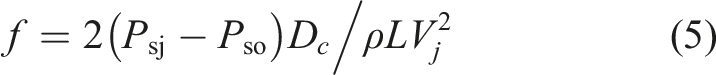
The drag coefficient is used to evaluate the flow resistance in the vortex chamber:
Thermal performance factor
21
is defined as follows:
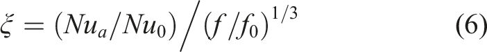
Nu0 and f0 are defined as follows:
21


Solution procedure and boundary conditions
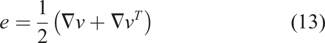
In this paper, the flow and thermal exchange properties for vortex cooling are explored by using the three-dimensional Reynolds Averaged Navier-Stoke equation and two-equation turbulence model. A second-order format with high accuracy is applied. Ignoring the actions of radiation thermal transfer and buoyancy, the transport equation can be simplified and expressed as follows:
The continuity equation:

The momentum equation:


The energy equation:

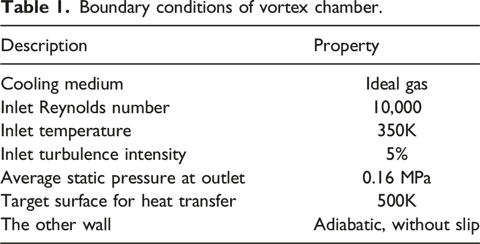
Boundary conditions of vortex chamber.
Turbulence model
The choice of turbulence model is closely related to the accuracy of simulation. Thus, this paper chooses to verify the turbulence model with the experimental and simulation results of Fan et al.
16
The Standard k-ε model, RNG k-ε model, Standard k-ω model and SST k-ω model are selected for simulation calculation respectively, and compared with the experimental results and the spanwise average Nusselt number with the Standard k-ω turbulence model of Fan et al.,
16
the results are shown in Figure 4. Both the Standard k-ω turbulence model and the SST k-ω turbulence model can accurately predict the vortex cooling process and the Standard k-ω model spanwise average Nusselt number has the highest agreement with the experiment. In this paper, the model mesh is segmented more precisely, so the model verification results are better than Fan et al.
16
Therefore, Standard k-ω model is selected to simulate vortex cooling process in this paper. Comparison for four turbulence models with experimental data. (a) Diagram of experimental verification device for turbulence model. (b) Validation of four turbulence models and comparison with experimental and Standard k-ω model of fan.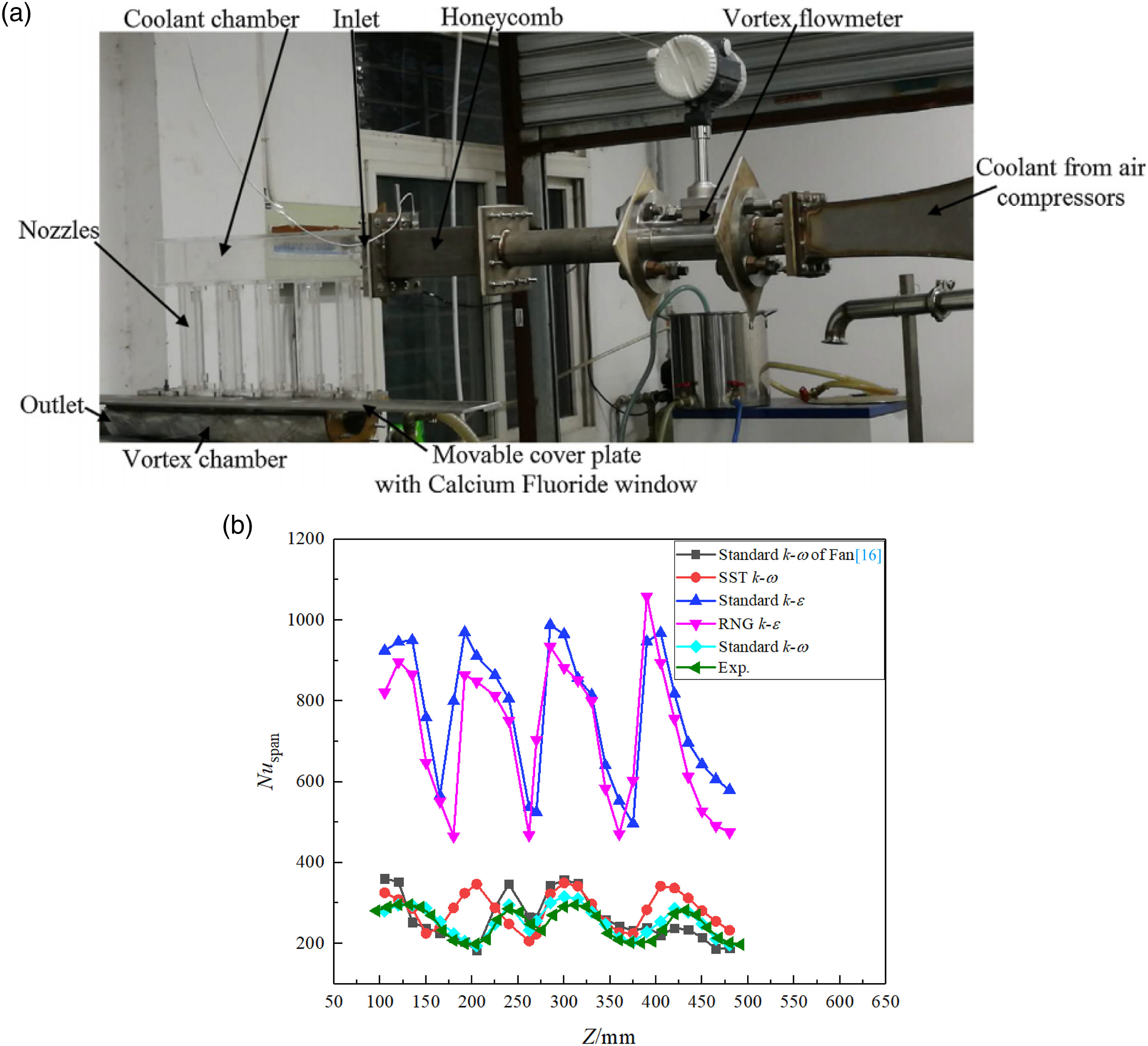
Mesh procedure
As shown in Figure 5, the computational domain is divided into hexahedral structured grids. H-type meshing is suitable for square geometric shapes, while O-type meshing is used for geometric structures with curved surfaces. Because of the curved surface, it is necessary to use O-type meshing for the vortex chamber. In addition, H-type meshing is used for the coolant chamber structure without curved surface, and O-type meshing is also used for Circle coolant chamber. The boundary layer near the wall surface is the hinge to vortex cooling thermal exchange, so the mesh is refined in the area near the wall. In order to meet the demands of turbulence model, the mesh height of the first layer y+ is less than 1. Mesh for computation domain.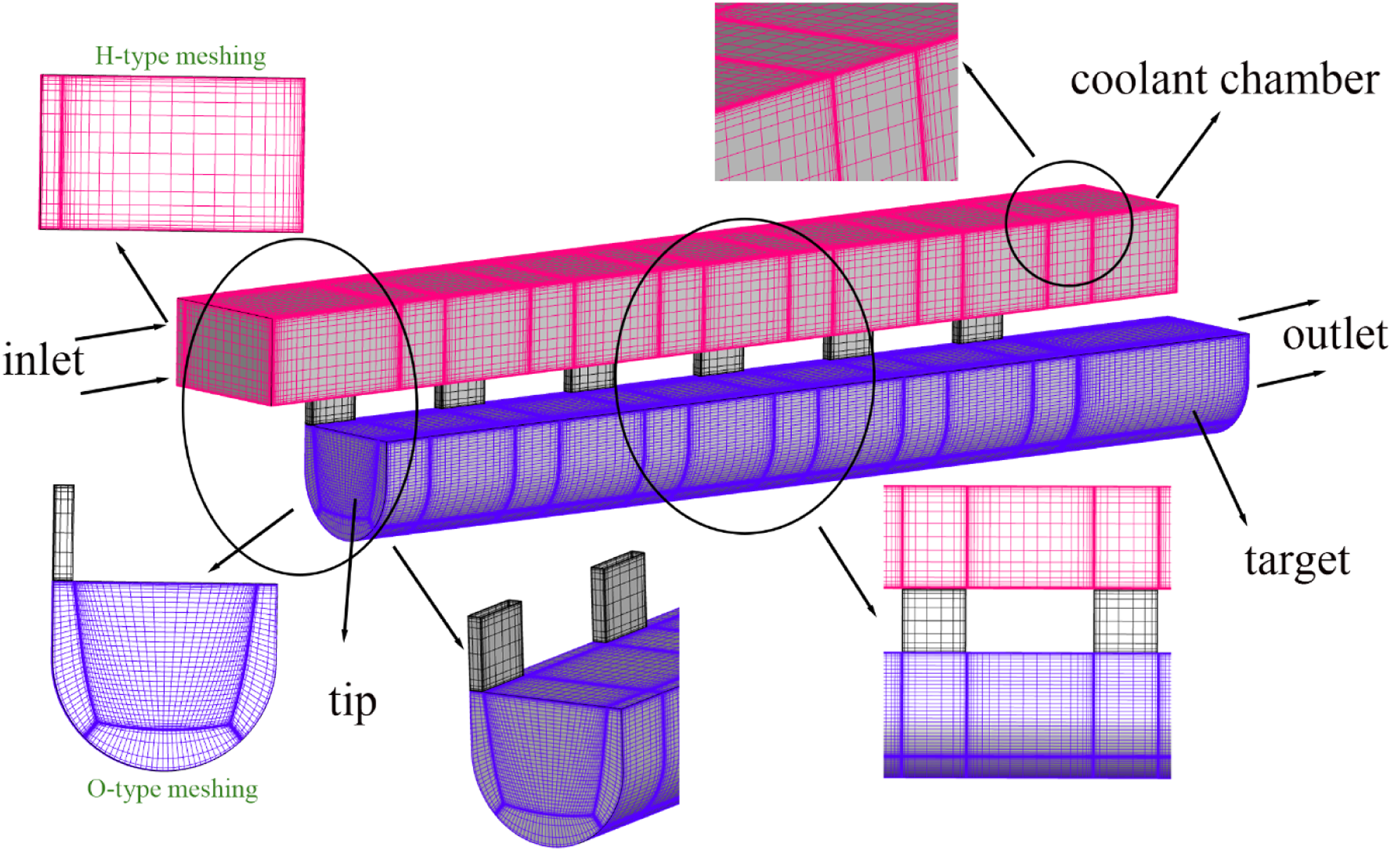
Grid independence analysis
Rectangle coolant chamber is taken as an example to conduct the grid independence analysis. Five grid numbers of 1.78 million, 2.61 million, 3.60 million, 4.60 million and 5.54 million are successively selected for comparison. Figure 6 shows the axial distribution of spanwise average Nusselt number in vortex chamber target surface under five mesh quantities. Obviously, the distribution trend of spanwise average Nusselt number is the same under different number of grids. As can be found from the Figure 6, when the number of grids increases to 3.6 million, the variation of spanwise average Nusselt number is no longer obvious. At this moment, the simulation results are not affected by the grids number. Therefore, combined with the accuracy and speed of simulation calculation, the final number of grids is selected as 3.60 million. Spanwise averaged Nusselt number trend for five grid numbers.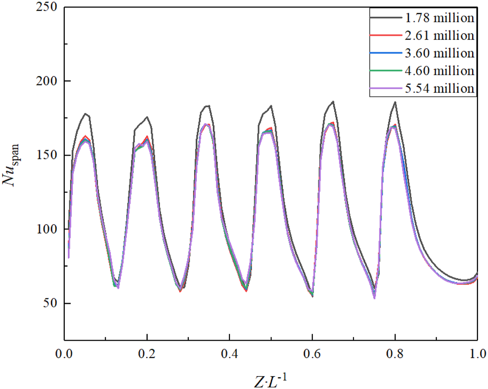
Results and discussion
In this paper, the XY section refers to the plane parallel to the entrance section, and the YZ section refers to the plane perpendicular to the entrance section. These expressions apply to all the discussion in this paper.
Flow characteristics for different cross-sectional shapes of coolant chambers
Figure 7 shows the velocity and three-dimensional streamline diagram of nine nozzles simultaneously incident on the vortex chamber under eight different structural models. The cool air enters the coolant chamber at the same inlet speed, and then the high-speed air flow is generated at the nozzle and enters the vortex chamber tangentially to form a rotating dynamic air flow. As the cool air in the vortex chamber continues to rotate downstream, the flow rate of cool air gradually increases in the chamber, which leads to the gradual weakening of circumferential motion and the gradual strengthening of axial motion. The cool air flowing in from the first nozzle is affected by the cool air flowing in from other nozzles, and the velocity significantly decreases in the vortex chamber downstream. 3D streamlines and velocity contour of eight configurations. (a) Rectangular. (b) Circle. (c) Trapezoidal up. (d) Trapezoidal down. (e) Ellipse up. (f) Ellipse down. (g) Sine up. (h) Sine down.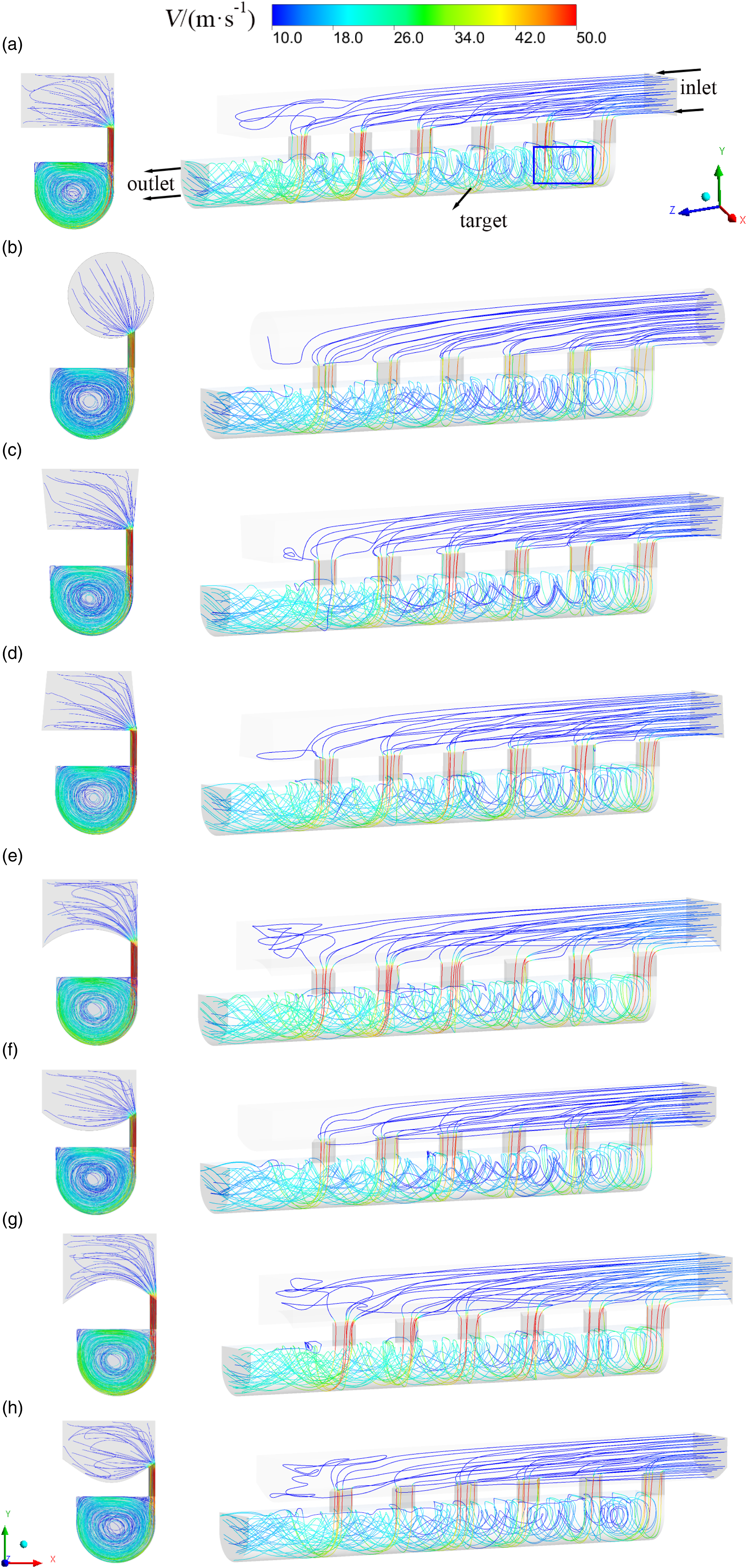
For Circular coolant chamber, the cool air flow velocity at the nozzle and vortex chamber is obviously lower than Rectangle coolant chamber. Thus, low-speed eddies will form in the central region of the vortex chamber. This is because the cool air flow resistance into the Circular coolant chamber is small, but the pressure into the nozzle is reduced and the impact force is decomposed, so the cool air speed is significantly reduced. The overall velocity difference between the two trapezoidal structures and Rectangle coolant chamber is tiny and almost negligible. For Ellipse up and Sine up coolant chambers, due to the lower wall of the coolant chamber faces concave, the velocity of cool air entering the vortex chamber is clearly increased, and the cool air resistance increases. Meanwhile, the flow along the wall and the center of the vortex chamber is faster than Rectangle coolant chamber. For Ellipse down and Sine down coolant chambers, the overall velocity distribution is lower than Rectangle coolant chamber. The reason for this phenomenon is that the protrusion of the coolant chamber minishes the impact for the cool air cross flow. The velocity of cool air migration to the downstream is also weakened, so the eddy scale near the jet gas is reduced.
Furthermore, Figure 8 displays the XY cross-sectional velocity contour and streamline distribution of the nozzles 2, 4 and 6. The cool air flow velocity for the coolant chamber is low in all models. For Rectangular coolant chamber, the cool air flows along the target surface and the velocity gradually decreases. When the cool air flows to each cross section, the location of the swirl center also changes. For Circular coolant chamber, the speed of entering the chamber and the overall motion is both slower, which is consistent with the trend in Figure 7. For Trapezoidal up and Trapezoidal down coolant chambers, the velocity change is almost small compared to Rectangle coolant chamber, so there is little reference value for industrial applications. For Ellipse up and Sine up coolant chambers, it can also be noted that the speed of cool air impact and mixing is accelerated. The faster cool air speed means that the flow is more intense, which is more conducive to heat exchange with the outside to achieve the purpose of cooling. However, the speed of Ellipse down and Sine down coolant chambers visibly slows down and the use of models is not recommended. Velocity distribution for eight configurations at XY planes. (a) Rectangular. (b) Circle. (c) Trapezoidal up. (d) Trapezoidal down. (e) Ellipse up. (f) Ellipse down. (g) Sine up. (h) Sine down.
Figure 9 demonstrates the static pressure distribution for eight configurations at vortex chamber longitudinal section. With the increase of cool air flow, the static pressure in the vortex chamber gradually decreases. It can be clearly observed that there are high pressure areas on the upper and lower walls near the inlet of the vortex chamber and the pressure at the center of the chamber is low. Due to the strong impact and blending of cool air and the main flow, there will be strong instability at the wall surface, so a small-scale eddy will be detected near the target surface. The size of this eddy will not change with the variable coolant chamber cross-sectional shapes. Pressure distribution for eight configurations at vortex chamber longitudinal section. (a) Rectangular. (b) Circle. (c) Trapezoidal up. (d) Trapezoidal down. (e) Ellipse up. (f) Ellipse down. (g) Sine up. (h) Sine down.
Compared with Rectangular coolant chamber, the pressure in the central area of the other seven vortex chambers are higher, and circular vortices with different density are formed at the inlet of the vortex chamber. In particular, Ellipse up coolant chamber does not form a concentric circular vortex at the vortex chamber inlet, but a small-scale eddy appears at the front of the target surface. Along the direction of cool air flow, the size of this eddy first increases and then disappears. At the same time, it can be distinctly discovered that a high-pressure area at the target surface and above the cavity of Ellipse up and Sine up coolant chambers is larger than the other models. This is owing to after the bottom of the two coolant chambers becomes an inwardly concave curve, the increase of the force area directly enhances the incoming velocity of the cool air, and the high-speed airflow impinges on the target surface to form a high-pressure area.
The spanwise averaged static pressure coefficient distribution contour for eight configurations along the axial direction is shown in Figure 10. The static pressure coefficient expresses the cooling static pressure distribution in vortex chamber. The static pressure of cool air gradually decreases along the axial direction, which is on account of the viscous force in the wall. Because the strong scouring power of cool air, the static pressure coefficient will visibly appear the pressure peak at the nozzle position. The pressure coefficient gradually decreases to near zero at the exit of the vortex chamber. When the coolant chamber is Rectangular, the static pressure coefficient is the largest, and the second is Sine up coolant chamber. Overall, the pressure distribution trend is consistent with Figure 9. Spanwise averaged static pressure coefficient Cps variation at eight configurations.
Turbulent kinetic energy can respect the level of velocity fluctuation, and the fluctuation of fluid velocity is closely related to the heat exchange capacity. The turbulent kinetic energy is higher, the more conducive to improve the intensity level of heat transfer is. The turbulent kinetic energy and streamline contour of XY section for eight vortex cooling structures are shown in Figure 11, which shows the turbulent kinetic energy distribution along the longitudinal section at nozzles 2, 4 and 6 respectively. As can be seen from the Figure 11, the cool air will distribute the flow to each nozzle and enter the vortex chamber when the cool air enters the coolant chamber. The turbulent kinetic energy which entering the vortex chamber is large at the downstream of coolant chamber, so the regions with different thickness of high turbulent kinetic energy will form and distribute along the wall of the vortex chamber. Otherwise, the turbulent kinetic energy increases as it moves downstream, mainly because the mixing effect of cool air is gradually enhanced, the cool air kinetic energy in the downstream of vortex chamber gradually increases and the impact jet constantly increases. Turbulent kinetic energy distribution contour for eight configurations at XY planes. (a) Rectangular. (b) Circle. (c) Trapezoidal up. (d) Trapezoidal down. (e) Ellipse up. (f) Ellipse down. (g) Sine up. (h) Sine down.
The turbulent kinetic energy of Circular coolant chamber is lower than Rectangle coolant chamber, and the heat transfer uniformity of Circular coolant chamber is the worst. The size of the turbulent kinetic energy distribution region of Trapezoidal up and Trapezoidal down coolant chambers is similar to Rectangle coolant chamber, but the streamline distribution is denser. Among the eight structures, the turbulent kinetic energy of Ellipse up and Sine up coolant chambers are the strongest and the streamline is intensive at the sixth nozzle. The turbulent kinetic energy of the cool air impacting on target surface is high, which leads to the strong mixing with cool air and the disturbance of boundary layer. It has a prominent impact on thermal exchange intensity at the target surface, which can provide a reference for the simulation and calculation of vortex cooling in subsequent practical engineering applications. But the turbulent kinetic energy intensity of Ellipse down and Sine down coolant chambers is between Rectangle coolant chamber and Circular coolant chamber, and the ability to convert heat is relatively inferior.
Heat transfer characteristics for different cross-sectional shapes of coolant chambers
Figure 12 shows the Nusselt number distribution on target surface based on variable cross-sectional shapes of coolant chambers. For Rectangular coolant chamber, the thermal boundary layer will be weakened by the erosion of cool air at each nozzle inlet, thus forming a high heat transfer zone, as shown in the red area in Figure 12. The cool air of the jet is less blended by the axial cross flow, because the cool air flows against the wall of the vortex chamber, and the thermal transfer strength for the target surface will increase along the axial downstream direction. Nusselt number distribution contour for eight configurations. (a) Rectangular. (b) Circle. (c) Trapezoidal up. (d) Trapezoidal down. (e) Ellipse up. (f) Ellipse down. (g) Sine up. (h) Sine down.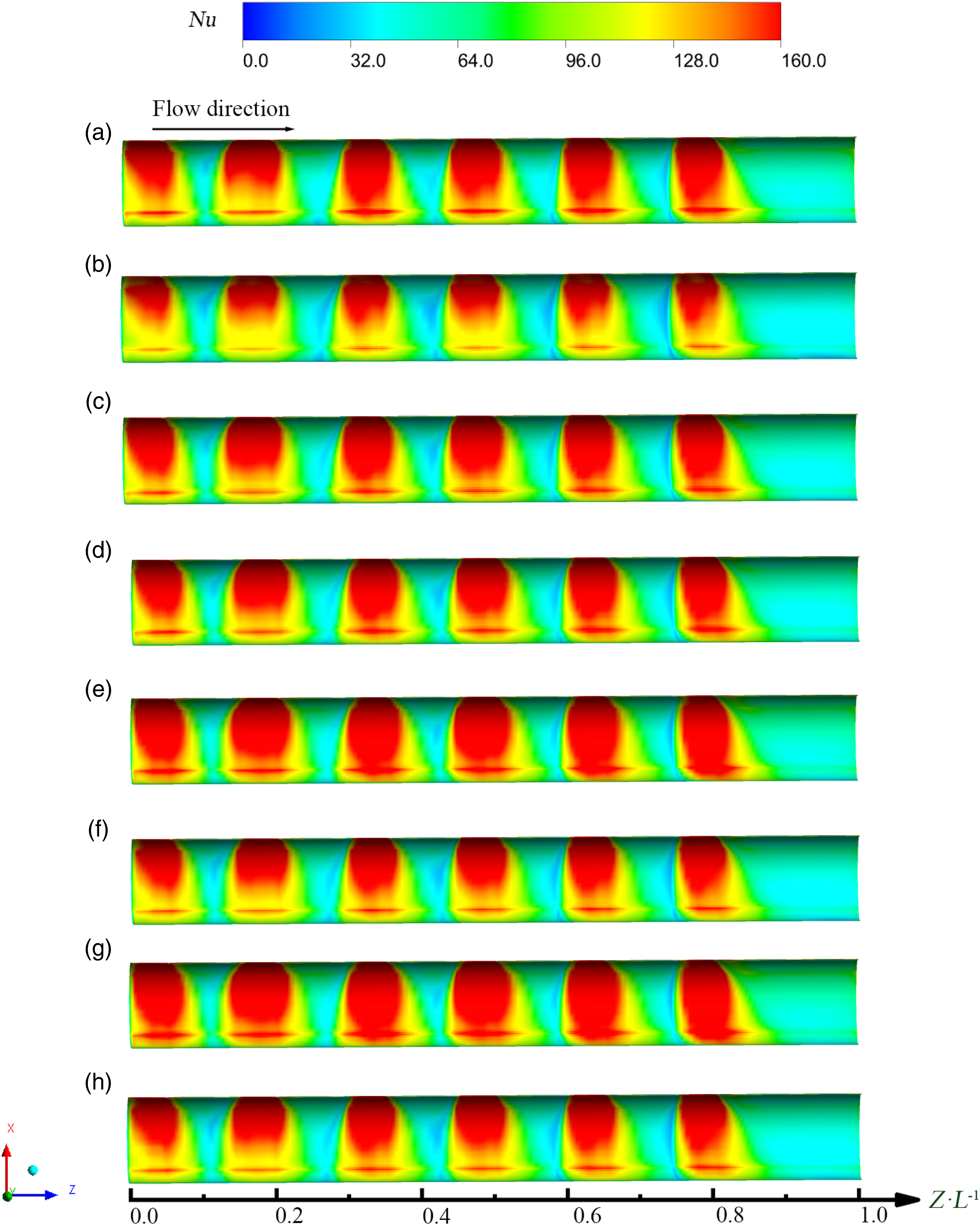
In Circular coolant chamber, the high transmission band is significantly reduced by nearly half, and the heat transfer capacity of the unwashed area between the two nozzles is greatly reduced. For Trapezoidal up and Trapezoidal down coolant chambers, the high-transfer zone is approximately almost the same as Rectangle coolant chamber, so the shape of Trapezoidal up and Trapezoidal down coolant chamber has less impact on heat exchange than that of Rectangle coolant chamber. This is mainly because the two sides of the trapezoid are skewed, which does not change the direction of cool air shooting vertically from the inlet, and has little effect on the speed of shooting into the nozzle. For Ellipse up and Sine up coolant chambers, the high heat exchange area almost fills the whole target surface with high thermal transfer performance, and the thermal exchange capacity of the overall area in the middle of the two nozzles is also greatly improved compared with Rectangle coolant chamber. The low Nusselt number region is hardly observed at the inlet of the vortex chamber target surface. On the contrary, the heat transfer identity of Ellipse down and Sine down coolant chambers is not as strong as Rectangle coolant chamber. It is owing to the stress area of the lower notch increases and the cool air resistance increases, which counteracts the air flow washed into the vortex chamber and weakens the thermal transmission. At the same time, the low Nusselt number area for the target surface which has not been washed by cool air between the two nozzles increases obviously.
The axial distribution of spanwise averaged Nusselt number is shown in Figure 13. As the shape for coolant chamber changes, the spanwise averaged Nusselt number also can make a difference. The Nusselt number peak appears at the location corresponding to the nozzle. According to the Figure 13, the heat transfer features of Ellipse up and Sine up coolant chambers are better than Rectangle coolant chamber, and the spanwise averaged Nusselt number in other structures are lower than Rectangle coolant chamber, which is consistent with the trend observed in Figure 12. Spanwise averaged Nusselt number contour for eight configurations.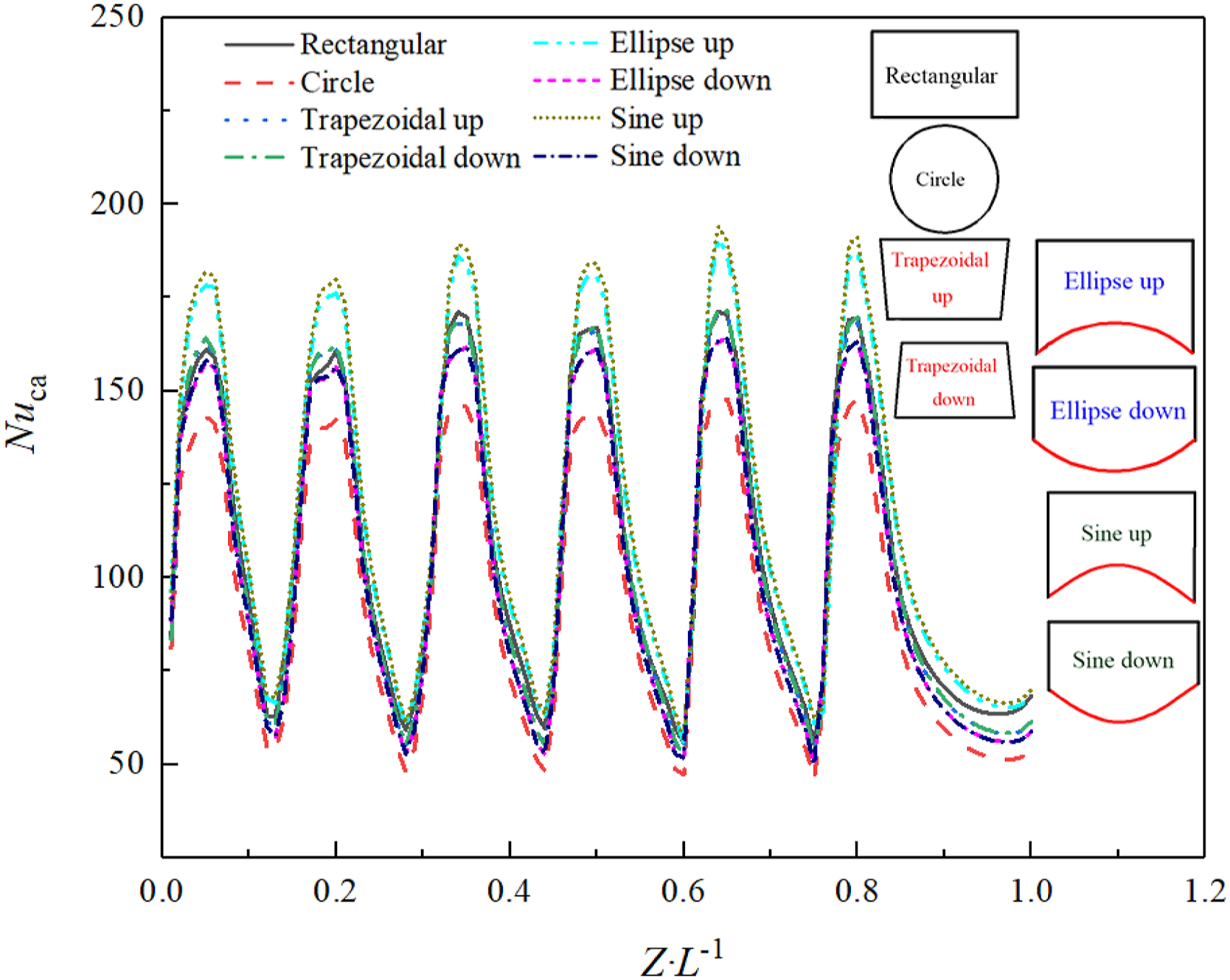
The temperature distribution at each nozzle for different coolant chamber models is revealed in Figure 14. When the cool air enters the vortex chamber from the nozzle, the temperature field in vortex chamber will be scoured by heat convection and heat diffusion. Generally speaking, due to the cross-flow shock of air flow, new cool air will be fully mixed at each nozzle to increase the kinetic energy, so the temperature at the center of the vortex chamber will be higher and higher as it moves downstream. However, with the blending degree of cool air gradually increases, a large half-moon shaped low temperature zone will be generated along the target surface, which will weaken the thermal boundary layer and enhance the thermal exchange strength. This also proves that vortex cooling is the most valuable internal cooling way. By comparing the distribution of temperature contour at the sixth nozzle, the temperature of Ellipse up and Sine up coolant chambers are the lowest, and a low temperature ring is formed in the center of the vortex chamber. But Circle coolant chamber has the highest temperature. Therefore, the heat exchange capacity of the upward notch is better than Rectangle coolant chamber, whether it is Ellipse up coolant chamber or Sine up coolant chamber. Temperature distribution contour for eight configurations. (a) Rectangular. (b) Circle. (c) Trapezoidal up. (d) Trapezoidal down. (e) Ellipse up. (f) Ellipse down. (g) Sine up. (h) Sine down.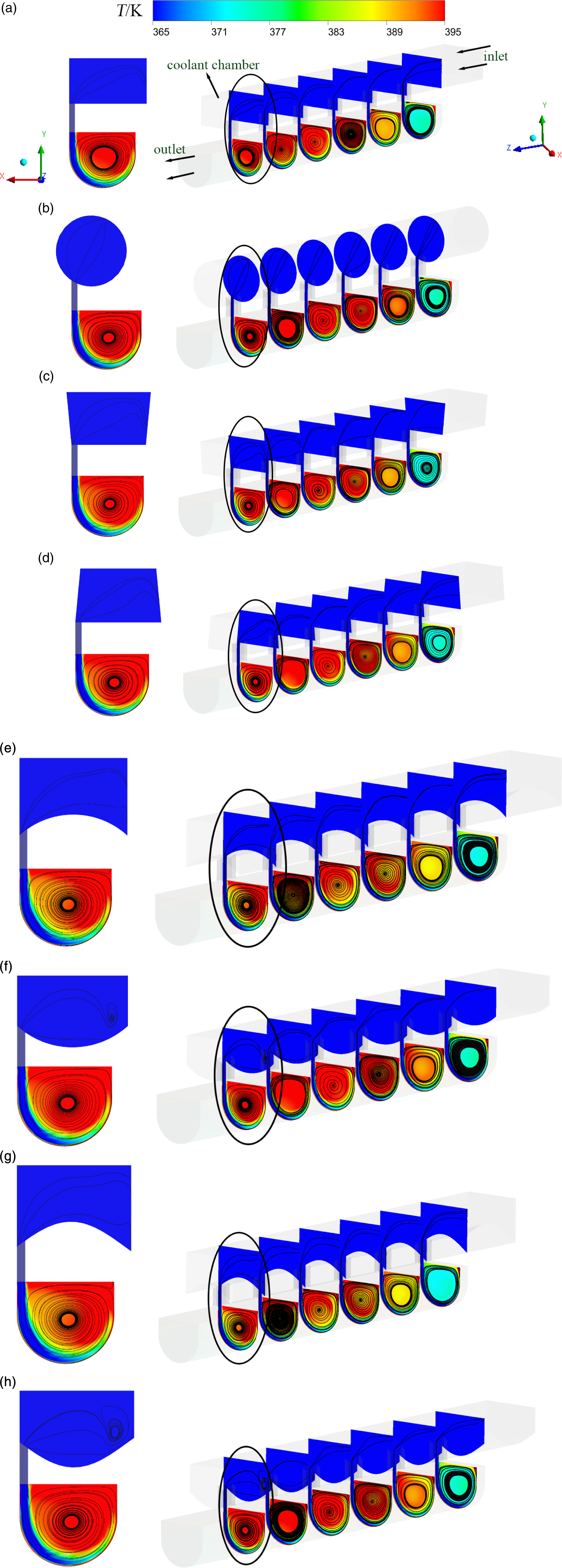
Target surface average Nusselt number, drag coefficient and thermal performance factor.
Conclusions
In this paper, eight three-dimensional models with variable cross-sectional shapes of coolant chambers based on vortex cooling are established. On the premise of affirming the mesh independence and turbulence model, the influences of eight cross-sectional shapes for coolant chamber on vortex cooling flow and thermal exchange behavior are investigated numerically. The main conclusions are as follows:
For Rectangle coolant chamber, the cool air enters the coolant chamber from the inlet and enters the vortex chamber at high speed through each nozzle, which will form high-pressure region in vortex chamber. Keeping the inlet Reynolds number in coolant chamber unchanged, the more the cool air flows downstream along the coolant chamber, the larger the turbulent kinetic energy entering the nozzle is. In addition, because of the high-speed erosion from cool air, a high transmission belt will form under the nozzle in the target surface.
For Circular coolant chamber, the cool air enters the nozzle at the lowest speed. However, the overall pressure distribution is higher than Rectangle coolant chamber. Similarly, Circular coolant chamber will also form a half-moon region of high turbulence kinetic energy at the tangential section, but the area is small. The high thermal exchange region is also the smallest among the eight models, and a typical reduction in heat transfer capacity can be found.
For Trapezoidal up and Trapezoidal down coolant chambers, the flow velocity, the overall streamline distribution and the area size of the high turbulent kinetic energy region are basically the same as Rectangle coolant chamber. If the actual engineering space needs, the Rectangle coolant chamber can be replaced without research bias.
For Ellipse up and Sine up coolant chambers, the velocity of the inner part in the vortex chamber is distinctly augment, and the low-speed vortex will not form in the chamber center. From the perspective of pressure distribution, concentric circles are not formed in Ellipse up coolant chamber, but small-scale eddies are formed at the target surface below the first nozzle, and the size of the eddies increases first and then disappears as the cool air moves downstream. The high turbulence kinetic energy areas of Sine up and Ellipse up coolant chamber are the largest, and the streamlines are dense at the nozzle 6. Overall, Sine up coolant chamber has the best comprehensive heat transfer capacity, and Ellipse up coolant chamber is the second highest, so Sine up coolant chamber is more suitable for blade leading edge cooling.
For Ellipse down and Sine down coolant chambers, the flow velocity is lower, resulting in a lower level of cool air flow. Although the overall turbulent kinetic energy is small and the thermal exchange homogeneity is bad, but the pressure in the vortex chamber is very well.
To sum up, different from the previous Rectangle coolant chamber, as long as the lower plane of the coolant chamber is concave, the flow and thermal transfer effects are better than the traditional rectangular coolant chamber. Therefore, the cross-sectional shape of the upward concave coolant chamber should be chosen reasonably for future experimental and numerical research.
Footnotes
Declaration of conflicting interests
The author(s) declared no potential conflicts of interest with respect to the research, authorship, and/or publication of this article.
Funding
The author(s) disclosed receipt of the following financial support for the research, authorship, and/or publication of this article: The authors gratefully acknowledge financial support from National Natural Science Foundation of China (No. 12102089).