
Abstract
In this numerical study, the impact of equidistant trapezoidal ribs on the characteristics of premixed H2-air micro-combustion was investigated, with a specific focus on the rib height. The study comprehensively examined flame structure, flame front position, flame speed, and combustion efficiency. A comparative analysis was performed between a backward-facing step micro combustor (MCSD) and micro combustors with varying rib heights: MCRD1 (0.5 mm), MCRD2 (0.6 mm), and MCRD3 (0.7 mm). The incorporation of trapezoidal ribs resulted in the creation of elongated and evenly distributed recirculation zones, significantly enhancing mixing and promoting flame stability, particularly at higher rib heights. The recirculation zones played a critical role in influencing the chemical reaction rate and the species distribution, leading to higher flame speed and greater combustion intensity. The findings highlight the outcomes of incorporating ribs in terms of combustion efficiency. The combustion efficiency values for MCRD1, MCRD2, and MCRD3 were recorded as 96.95%, 96.75%, and 96.61%, respectively, while the MCSD had a combustion efficiency of 97.14%. Hence, the recommended range of rib height is considered advantageous in ensuring an optimal balance between improved flame stabilization and maintaining a satisfactory level of combustion efficiency. The findings provide valuable insights for optimizing micro-thermophotovoltaic systems.
Introduction
Micro-combustion is an increasingly prominent area of research in the field of energy production, particularly within Micro-Thermophotovoltaic (MTPV) system technology. 1 MTPV systems utilize small-scale combustors and thermophotovoltaic cells to convert the chemical energy released from the combustion of hydrogen or hydrocarbon fuels into electrical energy. 2 These systems hold great promise for small-scale power generation in portable electronics, as well as UAVs, satellites, and remote sensors. 3 However, the micro-combustion characteristics differ significantly from conventional combustion in terms of flow behavior, heat transfer mechanisms, flame structure, chemical kinetics, and combustion efficiency. This miniaturization leads to the challenges of incomplete combustion risk and limited flame stability flow as surface-to-volume ratios is extremely high which results in shorter flow residence time comparing to the reaction time of some elementary chemical reactions.
Over the past two decades, 4 various approaches have been employed to address these challenges, with a particular focus on optimizing the geometrical configurations of micro-combustors in MTPV systems. This optimization process focuses on enhancing flame stabilization, heat transfer, and overall system performance. Indeed, the addition of a backward facing step in the experimental study carried out by Yang et al., 5 resulted in an increase in micro-combustor residence time, leading to improved mixing and expanded operating parameters. In addition, Sahota et al. 6 proposed a micro-combustor consisting of two backward facing steps, while Khandelwal et al. 7 conducted experimental research on a three-step cylindrical micro-combustor. Akhtar et al. 8 further expanded the studies to include micro-combustors with different cross-sectional shapes. The numerical analysis revealed that micro-combustors with trapezoidal and triangular cross-sections exhibited the most favorable performance overall. Jiaqiang et al. 9 noted that the efficiency of the emitter is most impacted by the equivalence ratio and least impacted by the flow rate of the mixture. Additionally, Jiaqiang et al. 10 discovered that incorporating a 45° angled backward-facing step enhanced the flame stability. Comparing experimental and numerical findings, Peng et al. 11 observed that the recirculation zones behind the steps significantly impact the flame location. On the other hand, Tang et al. 12 proposed a micro-planar combustor with parallel separating plates, and demonstrated that the thermal performance improved compared to a straight combustor, especially with an increase in the number of plates. Wenming et al. 13 found that the introduction of a block insert increases the temperature level and uniformity of distribution. Tang et al. 14 illustrated the advantages of utilizing a cross-plate in enhancing the blow-off limit and temperature level. Meanwhile, Wan et al. 15 found that the introduction of a central rod expanded the blow-off limits. The central rod also stabilized the flame location and improved its stability as it is stressed by Wan et al.16, 17 Kim et al. 18 found that increasing the vane angle in swirl micro-combustors, whether equipped with straight or twisted vanes, significantly enhances combustion stability, enlarges recirculation zones, improves wall temperature and heat transfer. Furthermore, the vane angle has a notable impact on combustion efficiency and pressure loss. Wan et al. 19 demonstrated that incorporating a bluff body significantly extended the blow-off limit, increasing it by three to five times compared to that of a straight micro-combustor. Moreover, Fan et al.20, 21 recognized that the flame blow-off limit depends significantly on the bluff-body dimension and shape. Zhang et al. 22 and Niu et al. 23 found that using hollow hemispherical and trapezoidal bluff-bodies considerably extended the blow-off limits. Lately, Yan et al. 24 and Pan et al. 25 discovered that utilizing a triangular pyramid and a ball shape can also expand the blow-off limits. Likewise, Zhang et al. 26 used numerical simulations to study the effects of multiple rectangular bluff bodies in a micro combustor. They found that these bodies increased the blow-out limit, influenced flame morphology, and sustained combustion efficiency better at high flow velocities. Raghavan et al. 27 investigated how slit-width in a micro-combustor with a centrally slotted bluff body affects combustion efficiency and exhaust gas temperature. Results varied with inlet velocity, showing initial improvement, followed by decline and subsequent increase in efficiency. Moderate slit-widths reached maximum temperature but were limited by flame splitting. Zuo et al. 28 discovered that the incorporation of ribs displayed the highest temperature levels and uniformity. Meanwhile, Pan et al. 29 observed that using pin-fin arrays improved the convective heat loss at the inner wall, and also improved flame sustainability. Chen et al. 30 enhanced a micro combustor using a rectangular rib, enlarging the recirculation zone and raising the wall temperature. However, increasing the horizontal step length led to decreased outer wall temperature due to higher thermal resistance. While, Ni et al. 31 conducted a numerical study of rectangular, ∩-shaped and ∪-shaped ribs, and founds that the ∪-shaped ribs showed the highest temperature level and uniformity. They also observed that employed two ribs delivered better thermal performance. Qamareen et al. 32 studied a 2D micro combustor with a backward-facing step and triangular wall fin, observing improved performance at lower inlet velocities (4-20 m/s) due to the fin blockage ratio. Fin location and shape affected temperature distribution and combustion performance. Conversely, Wan et al. 33 experimental and numerical study illustrated that the introduction of cavities resulted in higher thermal performance but increased the blow-off limits. Furthermore, the cavity gap distance, 34 the thermal conductivity of the wall material, 35 and the operating pressure 36 exhibited a considerable impact on the chemical and thermal performance. Su et al. 37 discovered that employed double wall-cavities attained higher thermal radiation efficiency. Peng et al. 38 demonstrated that the cavities significantly improve the chemical performance. In a numerical investigation by Li et al., 39 the impact of cavity aft ramp angle (θ) on combustion efficiency was explored. The study examined θ values of 90° and 135°, with combustion efficiencies of 95.8% and 93.5% observed at an inlet velocity of 24 m/s, respectively. However, at 28 m/s, the combustion efficiencies decreased to 56.9% and 84.6%, respectively. Gao et al. 40 developed a cavity combustor with guide vanes, resulting in higher temperatures and improved preheating and ignition effects compared to traditional designs.
The literature review reveals that previous studies have primarily focused on utilizing single techniques, such as steps, cavity configurations, or rib configurations, to enhance the thermal performance of micro-combustors. However, despite significant research efforts, the optimization of geometrical configurations remains an ongoing area of investigation, particularly concerning flame stability and thermal efficiency. Furthermore, limited research has been conducted on the implementation of multiple techniques and multiple ribs to improve micro-combustor performance. To address this research gap, the present study proposes a novel micro-combustor design that combines a backward-facing step with four equidistant pairs of trapezoidal-shaped ribs. This design aims to increase the convective heat transfer surface area and generate recirculation regions near the micro-combustor’s inner wall. By introducing angled edges on the ribs, the design aims to elongate the recirculation region size, enhance residence time, and provide a continuous ignition source. The numerical investigation in this study focuses on examining the impact of trapezoidal ribs and their height on combustion characteristics. To accomplish this, a comprehensive parametric study has been conducted to understand the effects of trapezoidal ribs on flame structure, position, flame speed, different reaction intensities, and combustion efficiency within the micro-combustors. Gaining insights into these characteristics is crucial for optimizing the performance of micro-combustion systems.
For this purpose, four micro-combustors configurations are developed in the framework of the present investigation. The goal is to assess the combustion characteristics of the newly proposed micro-combustor (denoted MCRD1), which has ribs with a height of 0.5 mm. Therefore, a comparison to the simple backward facing step micro-combustor without ribs (denoted MCSD) is conducted. Additionally, the impact of increasing the ribs height on the efficiency of the combustor is examined by comparing MCRD1 with two other micro-combustors, denoted as MCRD2 and MCRD3. MCRD2 and MCRD3 both have trapezoidal ribs with heights of 0.6 mm and 0.7 mm, respectively.
Geometric configuration
Figure 1 shows the schematic view and dimensions of the proposed micro-combustion chamber (MCRD1). A premixed H2-air mixture is fed with a uniform flow velocity of 6 m/s into the upstream channel (H1=2 mm, L2=2 mm), while combustion products are expelled through the downstream channel (H2=3 mm, t=0.5 mm). The total length of the micro combustor is L1=20 mm. The cavities have a length of L3=2 mm, and angled ribs have a height of h=0.5 mm and an angle of θ=45°. The choice of a 45° angle for the trapezoidal rib edges and the spacing between the ribs in the micro-combustor design is driven by the aim to optimize fluid dynamics, combustion characteristics, and thermal performance. The selected angle and spacing enables improved flow behavior, enhances flame stability and species distribution, and improved convective heat transfer area and the outer wall temperature uniformity. Moreover, increasing the heights of the trapezoidal ribs in the micro-combustor design positively impacts fluid dynamics, combustion characteristics, and thermal performance. The increased ribs height enhances mixing, improves flame stability, increases heat transfer area, improves convective heat transfer, and enhances outer wall temperature uniformity, as it is shown by our accepted work (Numerical investigation of thermal performance of hydrogen-fueled micro-combustor with trapezoidal rib, International Journal of Hydrogen Energy, Article accepted for publication 25 May 2023). These effects collectively contribute to optimizing the overall performance of the micro-combustion system. Schematic diagram and dimensional details of the proposed micro-combustor.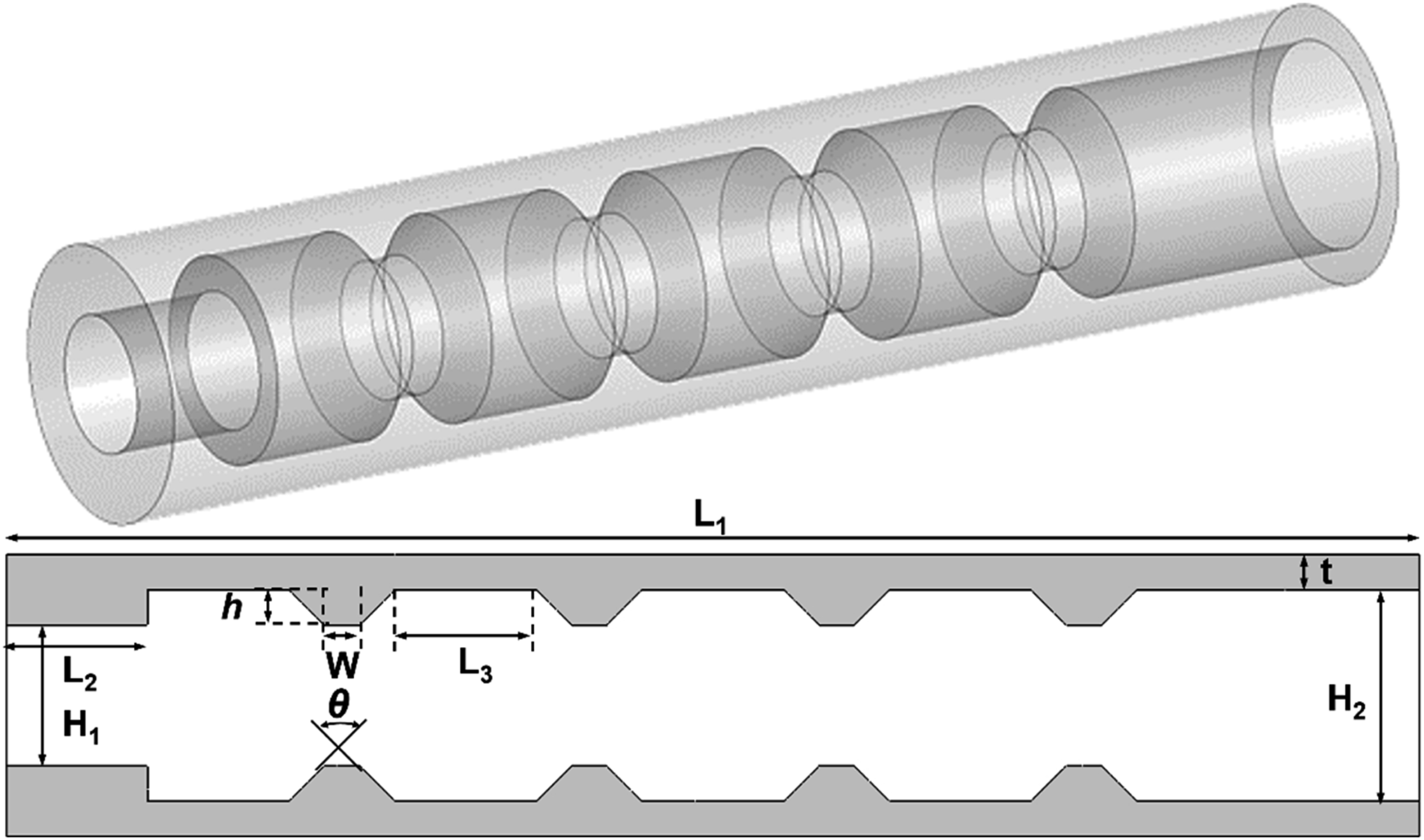
Mathematical model
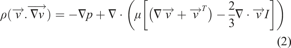
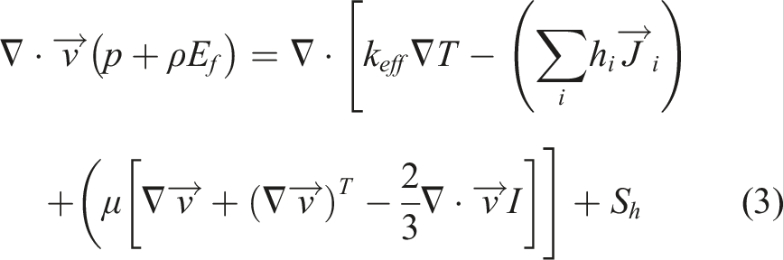
The mathematical model involves a system of partial differential equations that describe the conservation of mass, momentum, energy, and species at a steady-state, based on several suitable hypothesis. Mainly, the continuum medium assumption is valid as the Knudsen number is below the critical value. The H2-air is fully premixed at the entrance of the micro-combustor. The governing equations (1)–(4) for the fluid domain are:


The heat along the solid zone transport purely by steady-state conduction. Hence, the thermal gradients in the solid wall are calculated using the Fourier’s law:

316 stainless-steel was selected as the material for the micro-combustor due to its high thermostability and ability to maintain its structural strength at temperatures exceeding 2000°C. The density of the 316 stainless-steel
Chemical reaction mechanism of H2-Air Combustion. 42
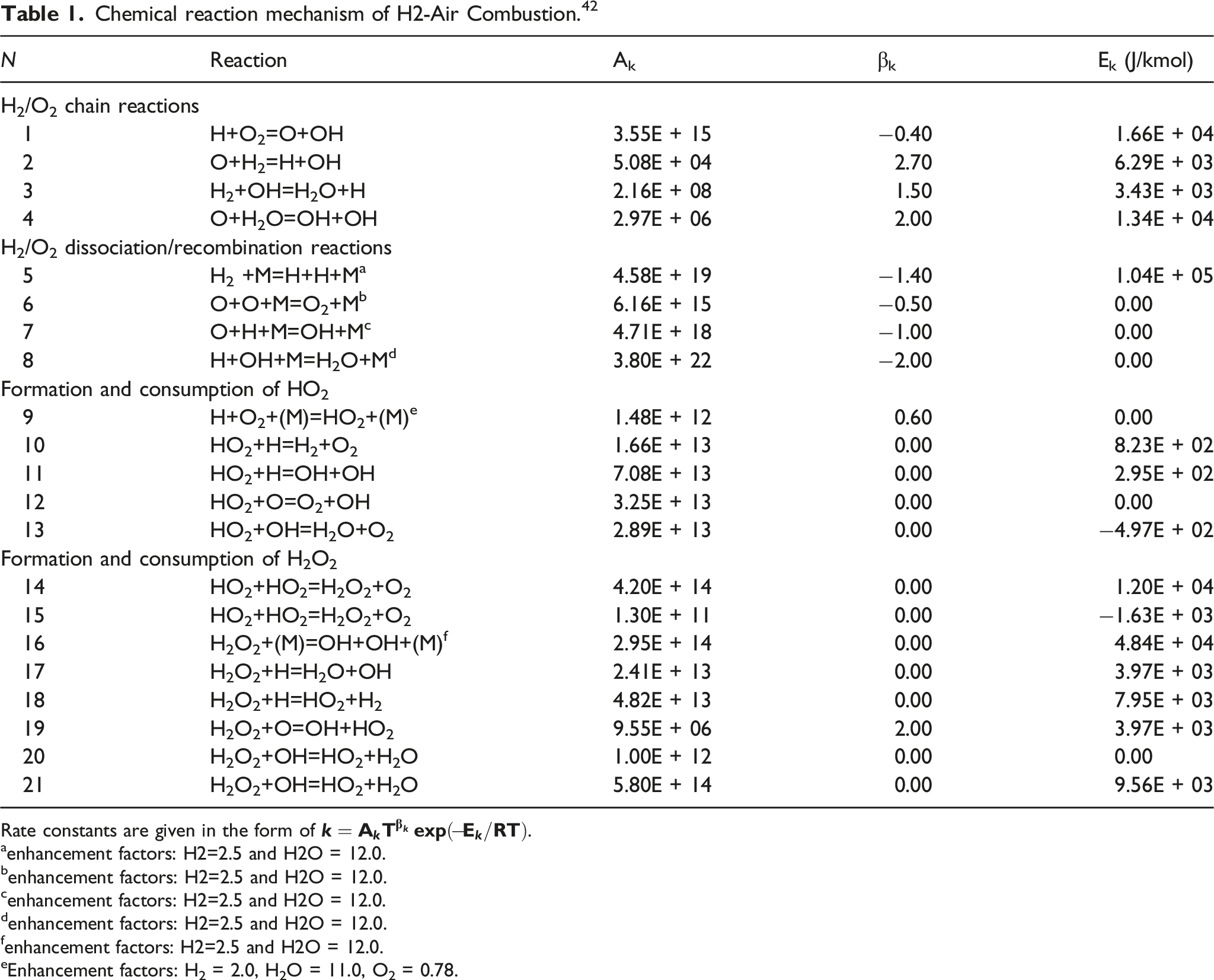
Rate constants are given in the form of
aenhancement factors: H2=2.5 and H2O = 12.0.
benhancement factors: H2=2.5 and H2O = 12.0.
cenhancement factors: H2=2.5 and H2O = 12.0.
denhancement factors: H2=2.5 and H2O = 12.0.
fenhancement factors: H2=2.5 and H2O = 12.0.
eEnhancement factors: H2 = 2.0, H2O = 11.0, O2 = 0.78.
On the other hand, the physical properties of H2-air mixture are defined as temperature and composition dependent functions. Hence, the mixture density is calculated using the ideal gas law, while, the specific heat and both viscosity and thermal conductivity of each species are computed by piecewise polynomial and kinetic theory methods, respectively. Meanwhile, the mass diffusion flux 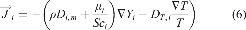
The mass diffusivity of the mixture (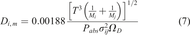
Numerical Modeling
Turbulence model
Considering the proposed configuration of the micro-combustor, the presence of turbulent fluid structures behind the trapezoidal ribs is anticipated. Hence, a turbulence model becomes essential to properly account for the viscous term in the momentum equation. Previous investigations28,43,44 have extensively demonstrated the significance of the turbulence model in accurately predicting the characteristics of micro-combustion. According to Kuo and Ronney, 45 this importance becomes more pronounced when the Reynolds number exceeds 500. In the case of the current micro-combustor, a critical inlet velocity of approximately 5 m/s corresponds to a Reynolds number (Re) greater than or equal to 500. Furthermore, based on the experimental study conducted by Li et al., 46 the inlet velocity should not fall below 6 m/s to prevent flashback into the upstream channel. Conversely, a velocity exceeding 16 m/s may result in undesirable acoustic emissions. It is worth noting that the selection of an appropriate turbulence model significantly influences the quality of the numerical simulations. For this purpose, the realizable k-ε model is selected in the present study, along with the standard wall function to capture near wall effects.
Combustion model
The reaction source term (R i ) quantifies the net rate of formation or consumption of each component species in every elementary reaction of the simplified mechanism. To incorporate the reaction source term (Ri) and complete the species mass transport equation, the eddy dissipation concept (EDC) model is chosen. This model is specifically designed for turbulent reacting flows characterized by rapid chemistry and considers the impact of turbulence on the reaction rate. In the EDC model, reactions are assumed to take place within small turbulent structures referred to as fine scales. Furthermore, the reaction rates are determined by the Arrhenius rates, which are computationally integrated using the ISAT algorithm. To calculate the initial reaction step, a stiff chemistry solver is employed to evaluate the first entry in the ISAT table. Since combustion involves the release of energy, the energy generated from chemical reactions corresponds directly to the rate of production or consumption of species i (R i ) in each elementary reaction. As a result, the energy source associated with micro-combustion reactions is appropriately considered.
Boundary conditions
The micro-combustor in question operates at standard atmospheric conditions, with a pressure of 1 atm and a temperature of 300 K. The H2-air mixture enters the micro combustor with a uniform inlet velocity of Uin=6 m/s, an equivalence ratio of φ=1.0, and temperature of 300 K. Furthermore, the no-slip condition is applied and the mixed (Robin) thermal condition is chosen, since the heat loss to the ambient surrounding is determined through both thermal radiation and natural convection. Therefore, the total heat loss rate is calculated as follow:
Numerical procedure
To solve the governing equations numerically, a 2D segregated solver with an under-relaxation method is used, and the finite volume method is employed implicitly. A double-precision pressure-based steady-state solver is also used. The SIMPLE algorithm is used for pressure-velocity coupling to ensure mass conservation and obtain the pressure field. The governing equations discretization uses the second order upwind scheme, and gradients are computed with the Least Square Cell-Based method. Under-relaxation factors are used to control the solution and stabilize the numerical error. The convergence criteria are set at 10−4 for all equation residuals and 10−6 for the energy equation. For stable combustion, the simulations follow a two-step procedure, starting with solving the equations at non-reacting flow conditions, followed by solving the equations at reacting flow conditions. ANSYS Fluent commercial software is used for simulations, with parallel computing using an 8-core processor and 24 GB RAM.
Grid independence analysis
The computational results are significantly influenced by the quality and quantity of the grid cells utilized. To achieve a balance between grid size and computational accuracy, a grid independence study is conducted. Six different structured grids consisting of quadrilateral cells with varying sizes are selected. The numerical tests are based on an inlet velocity of Uin=6 m/s and an equivalence ratio of ɸ=1.0. The centerline temperature profiles along the micro-combustor at different grid densities are presented in Figure 2. As a result, it is determined that an optimal grid size with 128,000 elements is sufficient for capturing temperature gradients and ensures result independence irrespective of the computational mesh. Grid independence analysis.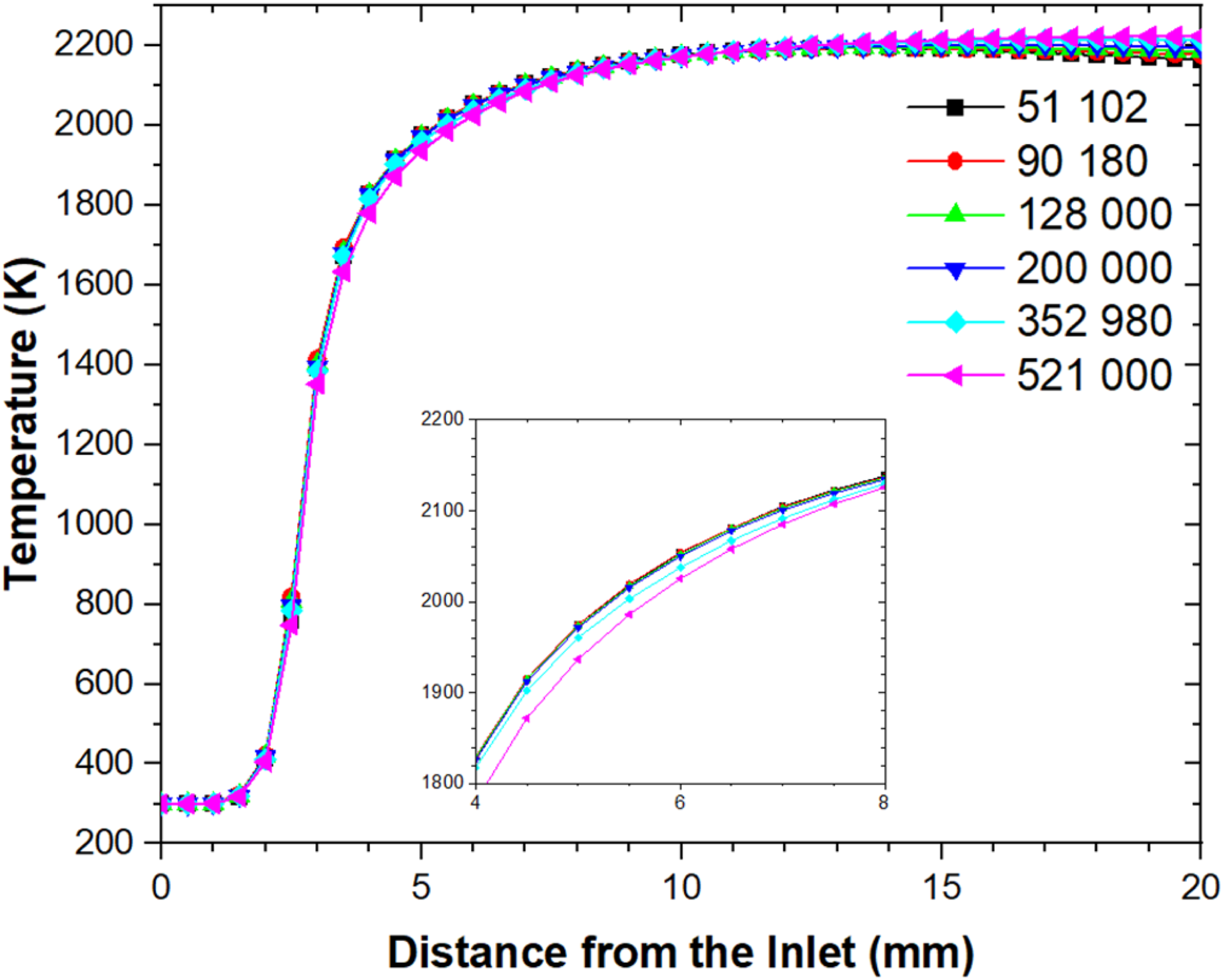
Model validation
In order to assess the accuracy and validity of the numerical methodology employed in this study, a comparison was conducted with the experimental data obtained by Tang et al.
47
The validation case focused on a single-channel micro combustor with dimensions of L1=18 mm, H2=4 mm, and t=0.5 mm, operating under the same chemical energy input of 36.63 W. To measure the temperature distribution on the micro combustor outer wall surface, Tang et al.
47
utilized an infrared thermal imaging device (Thermovision™ A40) equipped with a close-up lens ensuring clearer images. The measurements conducted by Tang et al.
47
were carried out in a controlled environment devoid of wind and light, maintaining an ambient temperature of approximately 20°C to minimize the influence of atmospheric radiation. Figure 3 illustrates the comparison between the experimental data and the current numerical results, demonstrating a favorable agreement overall. However, some discrepancies were observed in the upstream region within a 2 mm distance from the inlet. Nevertheless, beyond that point, the maximum relative error remained around 1% to 2%. Hence, the present numerical approach is reasonably reliable and exhibits a high level of agreement with the experimental data. Comparison of numerical and experimental outer wall temperature profiles.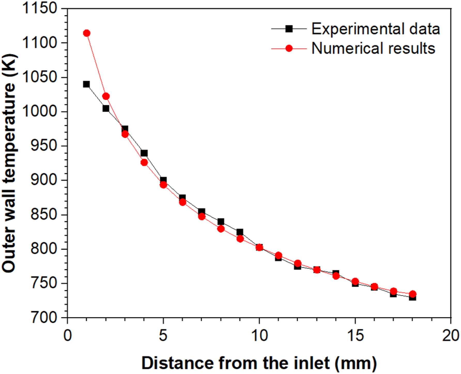
Results and discussions
Flame structure
Flame structure refers to the physical and chemical characteristics of a flame. The analysis of flame structure, aimed at comprehending the fundamental mechanisms of combustion, is crucial for optimizing combustion systems to achieve efficient and clean energy conversion. Thus, the species distribution and reaction rate, as well as the mass fraction contours of specific chemical species, are also used to understand the flame structure. Additionally, intermediate chemical reactions kinetic rates can be examined to determine the impact of the micro combustor's geometry on the micro combustion intensity.
Figure 4 presents the distribution of major species' mass fractions and the heat of reaction along the centerline of the micro-combustor MCRD1. The analysis of the profiles reveals the presence of three main zones in the reacting flow-field. The first zone, referred to as the preheat zone, represents the region where the cold reactants undergo preheating through heat diffusion from the nearby reaction zone. This preheating process initiates the destruction reactions of the fuel and the formation of intermediate radicals, thereby facilitating combustion ignition. The mass fraction of both the oxidizer and fuel decreases rapidly within the reaction zone, while the mass fraction of the product H2O and the intermediate radical OH increases proportionally, reaching its peak value at the front end of the flame. Subsequently, the mass fraction of reactants tends toward zero in the recombination zone, while the mass fraction of products gradually increases and stabilizes at the outlet of the combustor. Flame structure, major species and heat of reaction distribution along the MCRD1 centerline.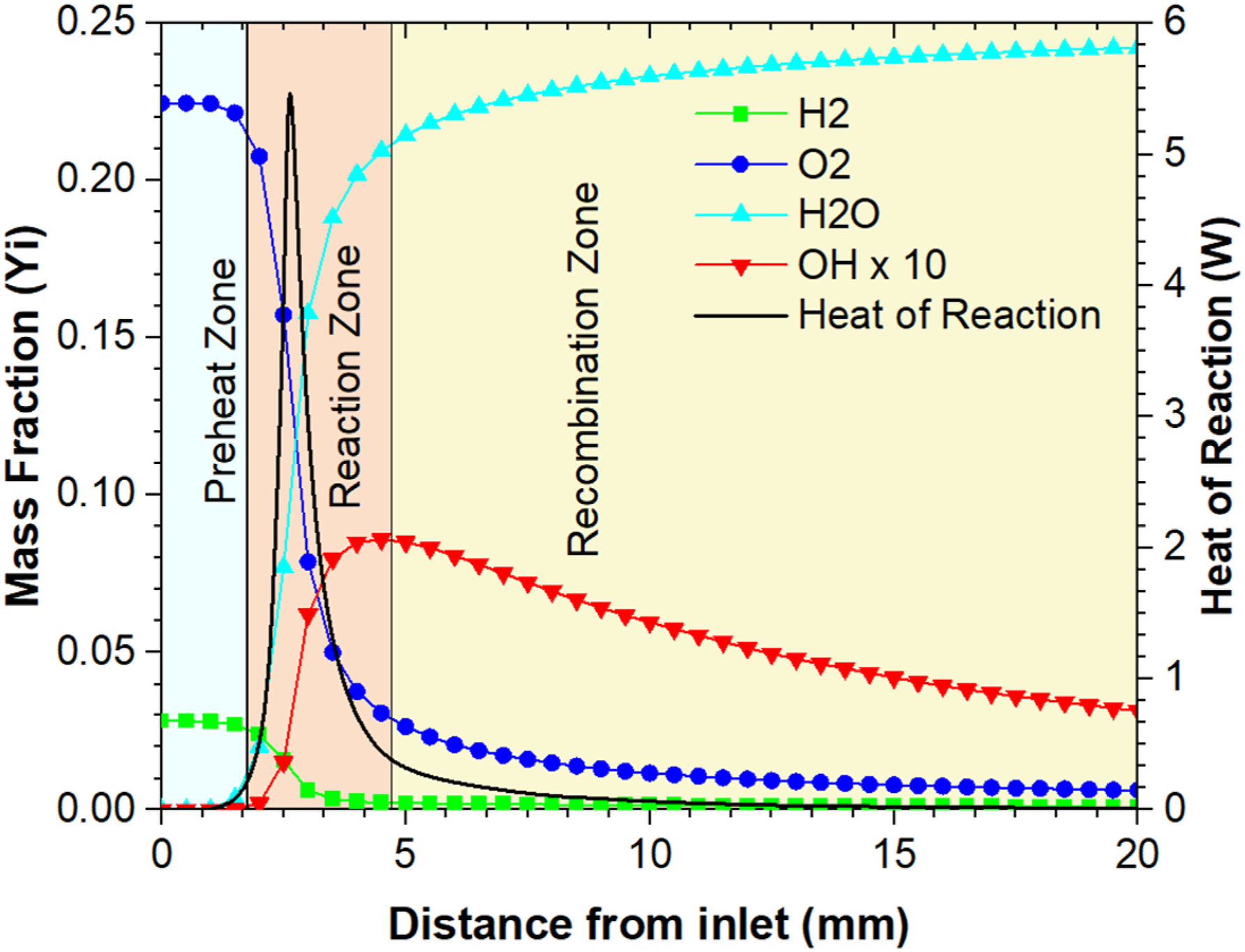
Figure 5 presents the net reaction rate of major species, including H2, O2, H2O, O, H, and OH, along the centerline of the micro-combustor MCRD1. The negative net reaction rate represents the consumption of reactant species, while the positive net reaction rate indicates the formation of products and intermediate species. Further analysis of Figures 4 and 5 reveals that the reaction zone is located between 2 mm and 4.3 mm from the inlet. Moreover, the net reaction rate of various species reaches its maximum value at approximately 2.625 mm from the inlet. The distribution of the net reaction rate of the major species along the centerline of MCRD1, with (a) representing the overall distribution and (b) providing a zoomed-in view on the reaction zone.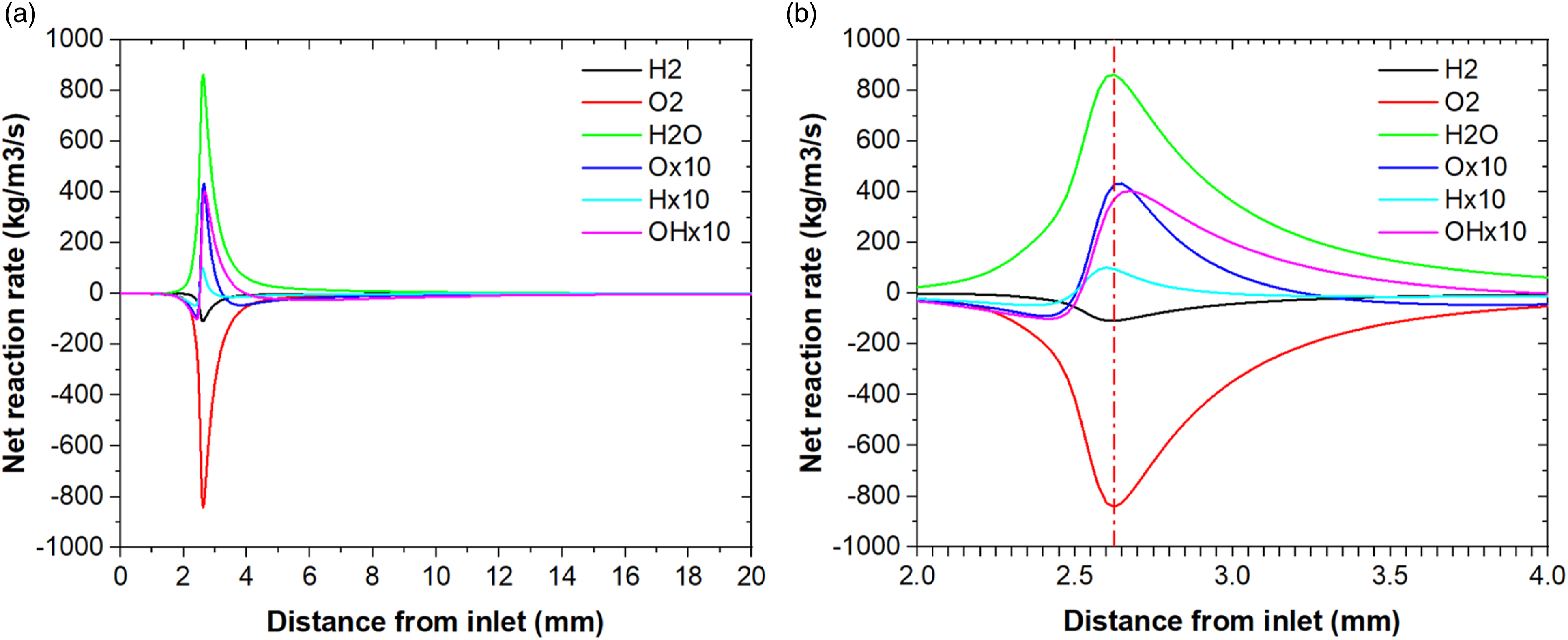
To clarify the geometry effect on the flame shape Figure 6 summarizes the H2 and OH mass fraction contours of the different combustors, respectively. It shows that the flame shape is infinitely thin and perfectly conical at the upstream channel (in yellow color) of the different combustors. It is clear that there’s no geometry effect on the flame shape. Although, the distribution of hydrogen mass fraction inside the different combustors is slightly influenced by geometry, especially by the first pairs of ribs and its height. Meanwhile, it can be seen from the Figure 6 that the MCRD’s OH radical mass fraction distribution is significantly affected by the pairs of ribs and the increment of its height. Li et al.
48
figures that the OH mass fraction distribution inside a micro combustor can be seen as an indicator to the reaction zone. As shown in Figure 6, the OH mass fraction expanses vertically and tends to divide into two parts away from the flame conical front toward the first cavity. Furthermore, the stretching of the reaction zones is observed to be induced by the generated recirculation zones situated behind the backward-facing step. The sloped edges of trapezoidal ribs allow smooth flow of combustion products and impede excessive stretching of the flame. Conversely, the combustion products trapped by the recirculation zone behind the backward-facing step and the first rib contribute in preheating the incoming cold reactants, which ensures the persistence of combustion and guarantees continuous ignition. The low velocity zones behind the ribs, pulled the flame radicals (OH, O, H, …) closer to the MCRD’s combustors inner walls compared to MCSD. The wrinkling of the reaction zone slightly increases with the increasing of the rib’s heights for MCRD2 and MCRD3, respectively. Therefore, the increase of the rib’s height further than the defined range (0.5–0.7 mm) can act as flow deflectors, resulting in the complete stretching of the flame. Hence, it is crucial to strike a balance between improved heat transfer and potential drawbacks associated with excess heat loss. As the height of the ribs increases, the larger convective heat transfer area can also lead to an increased loss of the heat released to the surroundings. This excess heat loss reduces the thermal efficiency of the combustion and may result in flame quenching. Likewise, the expansion ratio of the backward facing step must be carefully chosen to avoid the strong stretching of the reaction zone and consequently the flame quenching. Therefore, the ribs height could be used as a passive control technique to control the amount of the trapped gases along the combustor inner wall. H2 and OH mass fraction contours for the different micro-combustors.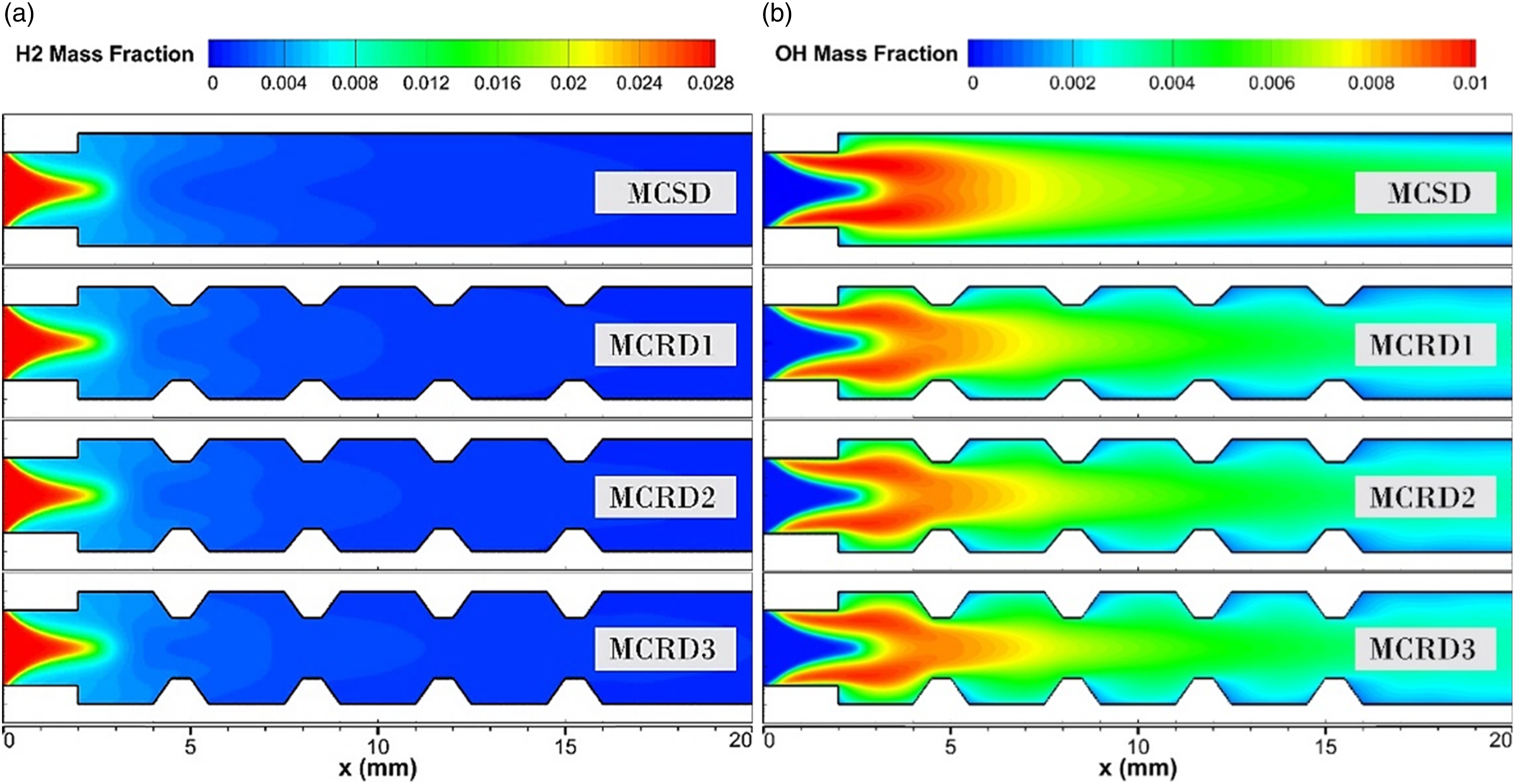
Furthermore, Figure 7 illustrates the average kinetic reaction rate of the different elementary reactions of the chemical mechanism for each micro combustor. As shown, an increase tendency is observed for these quantities (kinetic reaction rate of the different elementary reactions) with the implementation of the ribs. Besides, it can also be seen that the average kinetic reaction rates gradually increase with the increasing of the ribs heights to 0.6 mm and 0.7 mm, respectively. These differences are appearing more clearly with the elementary reactions R-3, R-4, R-8, R-9, R-16, R-17 and R-21. Based on these findings, it can be concluded that the introduction of trapezoidal ribs and increasing their heights have a favorable effect on flame sustainability and combustion intensity. The presence of the ribs enhances the interaction between the reactants and combustion products which promotes more efficient and vigorous chemical reactions. This, in turn, contributes to improved flame stabilization, ultimately leading to more efficient and reliable energy conversion systems. On the other hand, the increase of the rib’s height further than the defined range (0.5–0.7 mm) can act as flow deflectors, directing the combustion products away from the desired reaction zone and minimizing the flame sustainability and combustion intensity. Average kinetic rate of different elementary reactions for the different micro-combustor.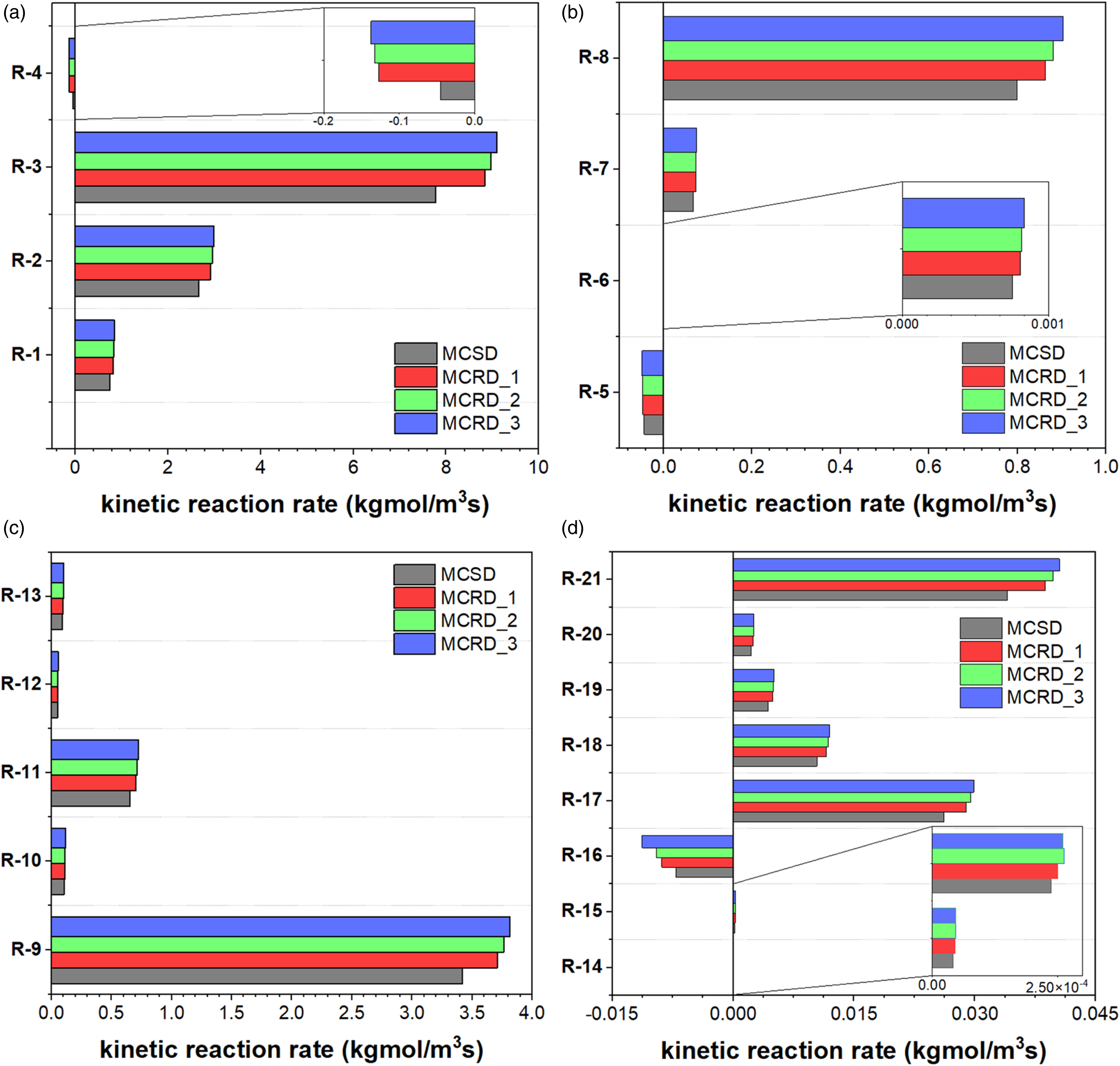
Flame front location
In order to clarify the effect of height ribs on the combustion characteristics, the flame front location, ignition distance and the flame speed are used as a characteristic’s parameters. OH mass fraction distribution inside a micro-combustor can be seen as an indicator of the combustion intensity as it was stressed by Li et al.
48
Consequently, the location of the OH mass fraction profile peak value is used as a characteristic parameter and defined as the flame front location in the present study. Figure 8 plotted the OH mass fraction distribution profiles along the different combustors’ centerlines under the same operating conditions. As shown, the OH mass fraction profiles exhibit a similar trend, but are shifted relative to each other. Moreover, the OH mass fraction profiles increase rapidly once the chemical reactions are initiated. However, the production rate of OH radical is almost similar for the different cases. Figure 8 also demonstrates that the peak values of the OH radical profile are obtained at specific locations within each micro combustor. In the case of MCSD, the peak value occurs at a distance of 4.17 mm from the inlet. For MCRD1, the peak is observed at 4.45 mm, while for MCRD2 and MCRD3, the peaks are located at 4.6 mm and 4.675 mm from the inlet, respectively. Furthermore, the mass fraction of the produced radical OH decreases then gradually within the rest of the downstream channel following different rates. Comparing to MCSD, the introduction of ribs shifted the flame front location by 6.71%, 10.31% and 12.11% for MCRD1, MCRD2 and MCRD3, respectively. These outcomes reveal the direct effect of the recirculation zones (low velocity zones) generated by the pair of the steps and ribs. Moreover, the increase of the rib height slips the flame front location more from the inlet. Hence, the rib height can also be used as a passive control technique to adjust the flame front location. According to Chattopadhyay et al.,
49
the ignition distance is defined as the distance from inlet at the combustor axis where half of the hydrogen fuel is consumed. Therefore, the ignition distance is located about 2.55 mm from the inlet for the different proposed combustors. OH mass fraction centerline distribution profiles for the different micro-combustors.
Flame speed
To measure the flame speed parameter in this study, the method proposed by Li et al.
48
is employed. This method relies on the linear relationship established by Yamamoto et al.
50
between the peak of OH concentration profile and the flame speed. The method involves analyzing the OH concentration profiles obtained in order to obtain the position of the peak concentration. The peak of the OH concentration profile corresponds to the location of the flame front, and the magnitude of the flow velocity at this location is directly correlates with the speed at which the flame propagates. Figure 9 shows the variations of the flame speed for the different geometry designs. As shown, the flame speed is of 27.82 m/s and 31.2 m/s for the MCSD and MCRD1, respectively. On the other hand, the flame speed increases to 36.64 m/s and 43.26 m/s with the increasing of the pair of ribs height to 0.6 mm and 0.7 mm, respectively. This comparison to MCSD illustrates that the flame speed increases by approximately 12.15% with the MCRD1 and by 31.7% and 55.5% with the increasing of the rib’s heights, MCRD2 and MCRD3, respectively. Flame location and flame speed for the different micro-combustors.
The observed increase in flame speed can be attributed to the heightened level of turbulence induced by the presence of the backward-facing step and the trapezoidal ribs in the micro combustor. This increased turbulence intensity has a significant impact on the diffusion rate of reactants and products within the reaction zone. The turbulent flow created by the geometry promotes a faster and enhanced mixing and interaction between the reactants and combustion products result in a more dynamic reaction zone. As a result, the incoming reactants are preheated to a greater extent, facilitating their rapid ignition and promoting a sustained and vigorous combustion process. The enhanced turbulent level and combustion intensity contributed also to the acceleration of the flame propagation speed.
Combustion efficiency
In order to assess the performance of combustion, the combustion efficiency 
Figure 10 illustrates the average mass fraction of hydrogen at the outlet boundary of the different combustors. Additionally, the figure presents the variations in combustion efficiency. It is evident that the remaining hydrogen at the outlet is relatively low compared to the inlet mass fraction. The unconsumed hydrogen mass fraction increases from 8×10⁻⁴ to 8.65×10⁻⁴ for MCSD and MCRD1, respectively. Furthermore, it is noteworthy that the unconsumed hydrogen further increases to 9.2×10⁻⁴ and 9.6×10⁻⁴ as the rib’s height reaches 0.6 mm and 0.7 mm, respectively. On the other hand, the same figure reveals a decrease in combustion efficiency for MCRD1 compared to MCSD, with values declining from 97.14% to 96.95%. Moreover, due to the aforementioned increase in flame propagation speed, combustion efficiency gradually decreases to 96.75% and 96.61% as the rib's height increases for MCRD2 and MCRD3, respectively. These findings highlight one of the detrimental outcomes of incorporating ribs in terms of combustion efficiency. Hence, it is recommended to adhere to the suggested range of rib height proposed in this study to guarantee a positive impact on flame stabilization and combustion efficiency. Outlet H2 mass fraction and combustion efficiency for the different micro-combustors.
Conclusion
The present numerical study aims to investigate the impact of introducing multiple equidistant distributed trapezoidal ribs on the combustion characteristics of premixed H2-air in a novel micro-combustor. Three different ribs height (0.5, 0.6, and 0.7 mm) are considered to examine and control the flame main features (structure, front location, speed), and then combustion efficiency. The findings provide valuable insights for optimizing micro thermo-photovoltaic applications and understanding combustion mechanisms for efficient and clean energy conversion. It is shown that the trapezoidal shape of the ribs has minimal impact on flame shape but significantly influences the distribution of OH radicals, promoting flame stabilization and increasing the combustion intensity. Introducing ribs provides advantages such as improved flame stability, increased convective heat transfer area, and enhanced mixing of reactants and combustion products. The trapezoidal ribs also shift the flame front by creating elongated recirculation zones, and increasing the rib height moves the flame front away from the inlet, resulting in enhanced flame speed due to heightened turbulence, mixing, and propagation. However, excessive rib height can adversely affect combustion efficiency. It is crucial to balance convective heat transfer enhancement with the risk of excessive heat loss, especially for rib heights exceeding 0.7 mm. Therefore, it is recommended to adhere to the suggested range of rib height (0.5 mm-0.7 mm).
Footnotes
Declaration of Conflicting Interests
The author(s) declared no potential conflicts of interest with respect to the research, authorship, and/or publication of this article.
Funding
The author(s) received no financial support for the research, authorship, and/or publication of this article.