
Abstract
Damage in mechanical structure causes a change in its physical properties and it will affect the real-time application. Cracks in a structure that distressed in model parameters like mode shape, and natural frequency. Its need to the identification of damage early to avoid catastrophic failure and increase the life of the mechanical structure. In this paper, a model for natural fundamental vibration analysis of cantilever beam with the inclined crack with different depths and different locations has been presented. The natural frequency of crack reduces by an increase in crack depth. The performances of results have been verified with finite element analyses software ANSYS, Experimental analysis and finally compare results with a neural network.
Introduction
Composite materials are nowadays increasingly used as an alternative to conventional materials, because of their high strength, weight saving, specific rigidity, and mechanical flexibility especially in the aerospace industry. The aim of vibration-based damage detection techniques is to determine the occurrence of structural damage, its location and severity. 1 In mechanical engineering applications such as turbine plates, civil, automotive, bicycle, mechanical, defense, marine, aviation, and aerospace.2–4 The majority of the research has been focused on detecting cracks utilizing natural frequency decreases or damping frequency increases. Damage or cracks in nature occur during load transmission, reducing the stiffness of the structure, and dynamic vibration produces changes in the damping ratio, mode form, and mass distributions.
Many research investigation conducted in the last 20 years has presented on presented composites as an alternative over many conventional materials as there is a significant enhancement in the structural, mechanical properties of fiber-reinforced composite material. Natural fibers have emerged as a “green” reinforcement in fiber-reinforced polymers for secondary load-carrying structural materials in engineering applications.5,6 Plant fibre has advantages that draw the attention of researchers and industrial players, including low density, good mechanical qualities, and biodegradability. Silk is another natural fibre with balanced strength and toughness, which animals, particularly silkworms, make. Its density is even lower than that of plant fibres (1300 kg/m3).7,8 In southern part of India, the cocoon production from Bombyx mori silkworms has been over half a million tons every year for the past decade. In light of this, the tough and ductile natural silk fibre could offer a supplement reinforcement for FRPs designed for impact-critical engineering applications.
Adams et al. 9 developed a polymer reinforced fibers plastic with decreased stiffness and increased damping frequency. A crack or damage can be seen in bulk materials specimens in numerous locations. The extent of the damage has a natural frequency that fluctuates depending on how serious the harm occurs. Carbon fiber reinforced polymer composites, which are commonly used in aerospace and aeronautical engineering to reduce weight, were explored by Reis et al. 10 Composite materials have a number of benefits, including high specific stiffness, strength, and corrosion resistance. These materials, on the other hand, are particularly susceptible to damage and cracking. According to Ratcliffe and Bajaria 11 delamination is the most common flaw in composite materials, and it is difficult to notice with our natural eyes. Doebling et al. 12 use simple techniques of nondestructive method for determining if damage is local or global. Murigendrappa et al. 13 have presented a method for identifying local fractures using ultrasonic and X-ray imaging. Vibration analysis is based on changes in physical characteristics such as mass, damping, and stiffness, as well as changes in natural frequency, mass damping frequency, and mode shape diagram, to identify structural health monitoring.
Udwadia 14 proposed a straightforward approach for calculating the stiffness matrix of mechanical and structural systems using measured natural frequencies and related mode shapes. Several research studies have suggested using natural frequency to identify damage, and they showed the efficiency of this parameter in the case of a single damage location. 15 A single crack was located using a cantilever beam's first four natural frequencies. 16 Using a damage identification technique, it was possible to locate and measure the size of a single fracture in an experimental single-story frame from structures in the first three natural frequencies. 17 A study was conducted to see whether it was possible to identify a single crack in a vibrating rod by using the shifts in two natural frequencies caused by damage. 18 A methodology for identifying damage to a numerical model of a beam on an elastic basis that relies on natural frequency changes was examined. 19
The Artificial Neural Network (ANN) is a branch of the artificial intelligence and has been developed rapidly since the 1980s, the ANN has trained the vibration data collected by dynamic testing as well as those calculated from the analytical model and experimental model in traditional model-based detection approaches.20–22 Global optimization techniques such as genetic algorithms (GAs), 23 fuzzy logic, 24 particle swarm optimization (PSO),25–27 and hybrid approach like genetic fuzzy systems 28 have been developed to provide a more accurate and reliable solution. All of these approaches have advantages and disadvantages. However, due to faster and more accurate predictions of global optimization to the objective function, soft computing techniques based on ANN29,30 are gaining popular. Yau 31 has presented the cracked beam of natural frequency at different loads, they were applied as the input of crack location, crack size and compressed load, and choose the output as the natural frequency. More research current use curvature mode shape method has been practiced for damage location to composites structure.32,33 Zapico et al. 34 has used as natural frequency a mode shape of input of neural network, were calculated the before and after damage of structure specimen has use to predicate location, damage severity and compare with the analytical results. The proposed model has been applied on cantilever beam to identify the damage severity. Different crack location and depth of crack location has been estimated a relative natural frequency, the performances of result have been verifying with finite element analyses software ANSYS, Experimental setup and results with an artificial neural network with MATLAB.
The review of the research presented above reveals that the development and characterization of glass fibre-reinforced polymer (GFRP) composites and Bombyx Mori (SILK) have been exciting topics for research. This study presents a new class of glass fiber/epoxy/Bombyx Silk composite reinforced with different crack (10%,20%,30%,40%,50%) with different location of the hybrid composite materials. The mechanical characterization has been carried out through tensile test, and impact test.
To determine the accuracy of the experimental work, stiffness matrix calculation and the behavior of the natural frequencies and modes, analyses are conducted and compare with ANSYS 2022 software. The modes' alterations in appearance order (modes shifting) and shape (modes mutation) are investigated in particular. According to numerical results, highly accurate results can be produced at a low computational cost. Finally, the result is compared with ANN methods. The aim of vibration-based damage detection techniques is to determine the occurrence of structural damage, its location and severity. The results of paper have following orders, the section should be Method formulation of Induced Relative natural frequency curves, Fabrication and Experimental Method of Hybrid Composite Beam section gives a Fabrication and Experimental values, respectively Results and Discussion section, has results and discussion and Application of ANN section has application of neural network.
Method of formulation of induced relative natural frequency curves (IRNFC)
Concentrated damage is the most common composites materials. The inclined crack and obstacle in an elastic beam have change in natural frequency. The effect of concentrated damage crack on the natural frequencies of beams has been extensively investigated and an explicit equation of IRNFC with damage location and severity has been derived as by Gilbert et.al.
35
The frequency expression as a mathematical formulation has shown in equation (1).
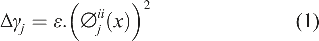
By comparison, the impact of delamination on the fundamental frequencies of laminated composite beams is a more sophisticated process that requires more investigation to comprehend fully.
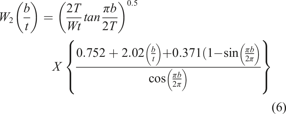
The term
Simulation of delaminated composite beam
Consider the laminated composite beam with L is length, W is Width, t is thickness, a is depth of the crack, Geometry of crack cantilever beam.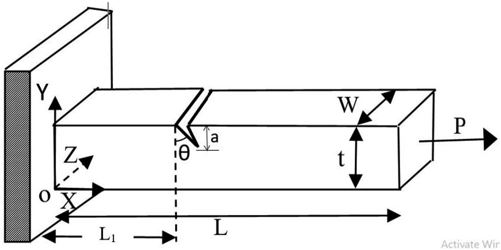
With the Finite Element programmer ANSYS, a delaminated composite beam is simulated. The layer information of the laminated beam is defined in the shell section, and a 3D layered solid element (Solid 185) is used. The mesh diagrams of cantilever beam have shown in the Figure 2. (a) Finite element mesh model of the cracked cantilever beam (b) Magnified view of the cantilever crack beam.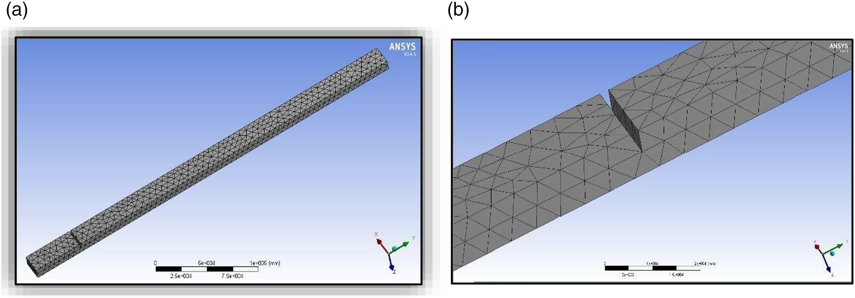
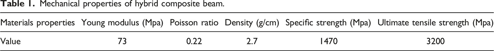
Mechanical properties of hybrid composite beam.
The element of meshes is used in the finite element model to measure fracture propagation research. To adjust the model with real structure, the hybrid composite beam element’s properties are modified. Therefore, a substantial number of matrix members may change in most circumstances. It poses a severe challenge to the damaged location.
Mathematical formulation of inclined crack beam formulation
Numerical analysis of inclined crack beam subjected to dynamic loading
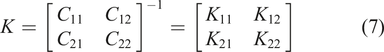
A beam with crack has smaller stiffness than the normal beam. It will decrease local stiffness can be formulated as a matrix. The dimension of the matrix would be degrees of freedom on this problem. Figure 1 shows a cantilever beam width W, thickness t, Length L, depth of crack a, inclined crack angle
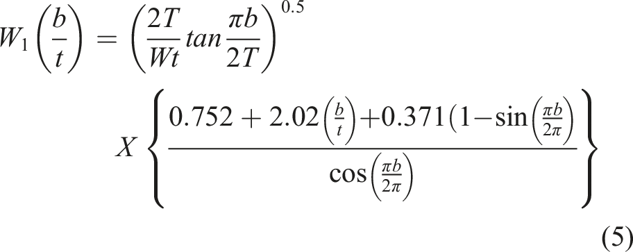
The relationship between strain energy release rate (b) and stress intensity factors GIi
ii, i = 2 to 2 (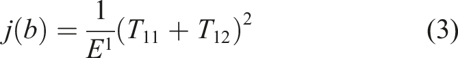
From the earlier studies,
36
the values of intensity factors are (4)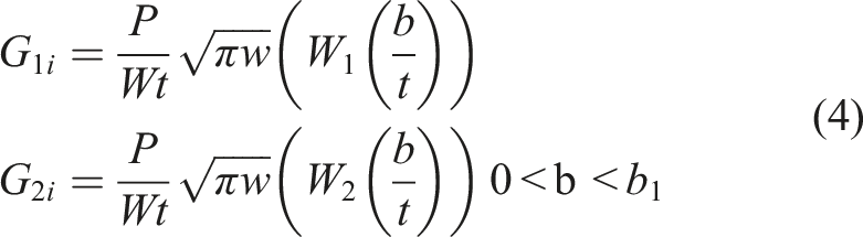
Vibration analysis of inclined crack beam
Cantilever beam of inclined crack is fixed at one end and free at another end, and uniform rectangular cross section. The natural free vibration of Euler-Bernoulli beam is given the following governing equation (9)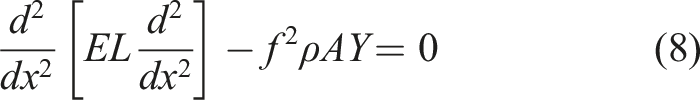
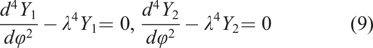
Solving the equations (8) and (9) of beam, the simplify of the results as follows in (10) and (11)

Fabrication and Experimental method of hybrid composite beam
Fabrication of hybrid composite beam
The overall performance of the green product can be impacted by the use of composite components and the appropriate manufacturing technique. To remove water, fiberglass and Bombyx Mori are cut to 30 mm, extruded, and allowed to dry naturally. After 3 hours of cleaning with a 5% NaOH solution, fibreglass and Bombyx Mori are repeatedly cleansed with distilled water until the pH reaches 7. After 1 day of ambient drying, fibre glass and Bombyx Mori were dried for 8 hours at 80°C in a vacuum oven. Using a mechanical agitator, epoxy resin and curing agent (10:1 wt ratio) were combined. The hand-lay method is used to pour the matrix material into the mould. Entire process continues watching until reaching the required thickness and weight percentage of yarn to be investigated, and allowed to dry at room temperature for 30 h. Samples should be preserved and measured for properties.
Experimental method of hybrid composite beam
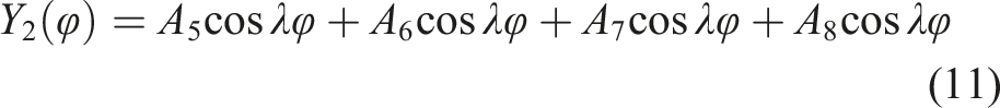
Experiment platform was constructed in the laboratory has shown in Figure 3. The experiment platform consisted of one fixed basis, one anchor heads, an acceleration sensor, a jack, a hammer, a spectrum analyzer, a magnetoelastic instrument, and a display units’ computer. Block diagram of experimental setup for cantilever beam.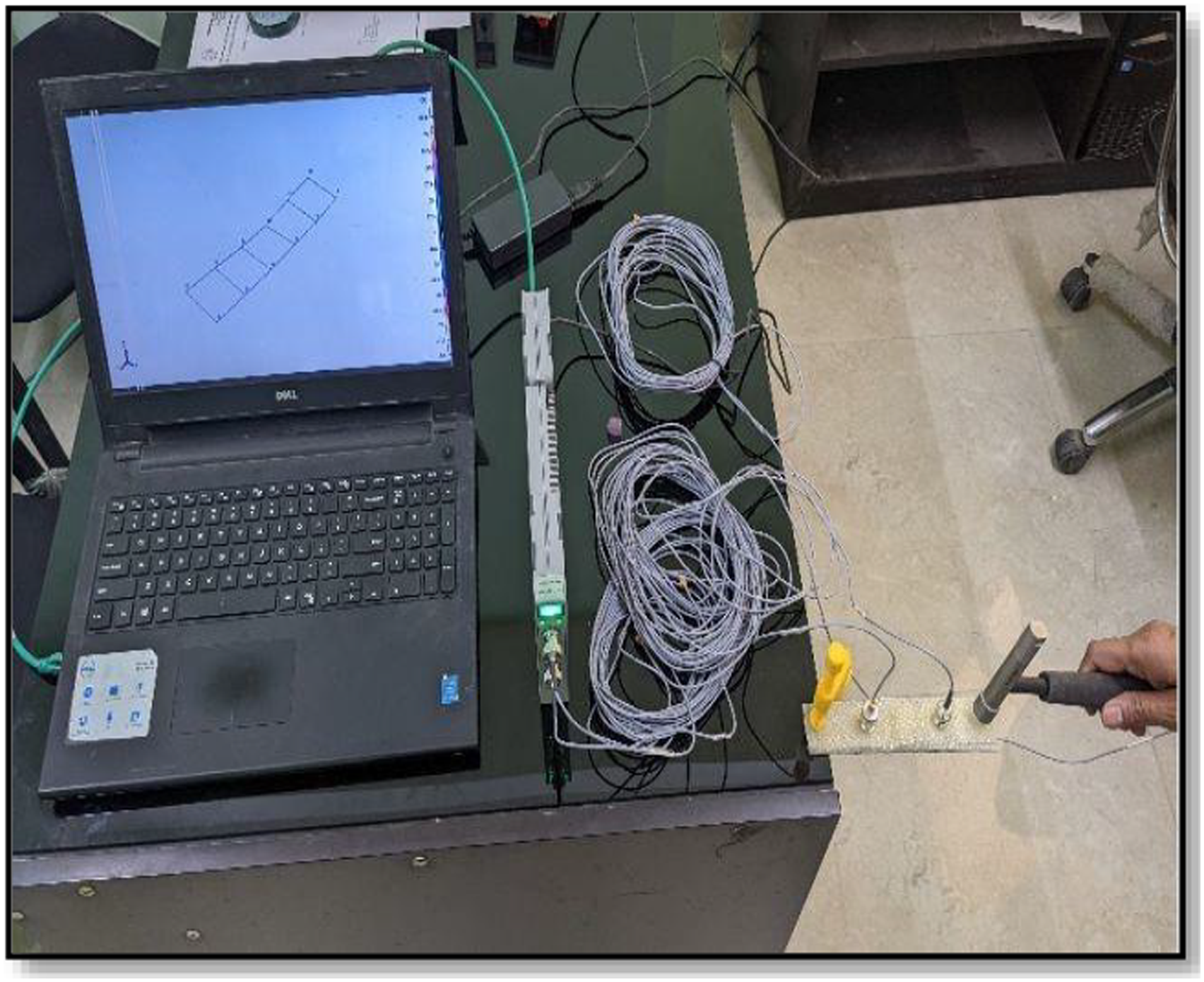
When the hybrid composites beam was struck by the hammer, its vibration acceleration was picked up by the acceleration sensor. The collected vibration acceleration signal was Fourier transformed by the spectrum analyzer, and thus, each order natural frequency of the steel strand was acquired. The experiments are run four times: the first time on an undamaged beam to assess mode shapes and the remaining three times with cracks inserted at relative depths of 0.1, 0.2, 0.3, 0.4, and 0.5 to determine natural frequencies Figure 4 Mode Shape Diagram of ANSYS software. (a) First Mode Shape (b)Second Mode Shape (c) Third Mode Shape (d) Fourth Mode Shape.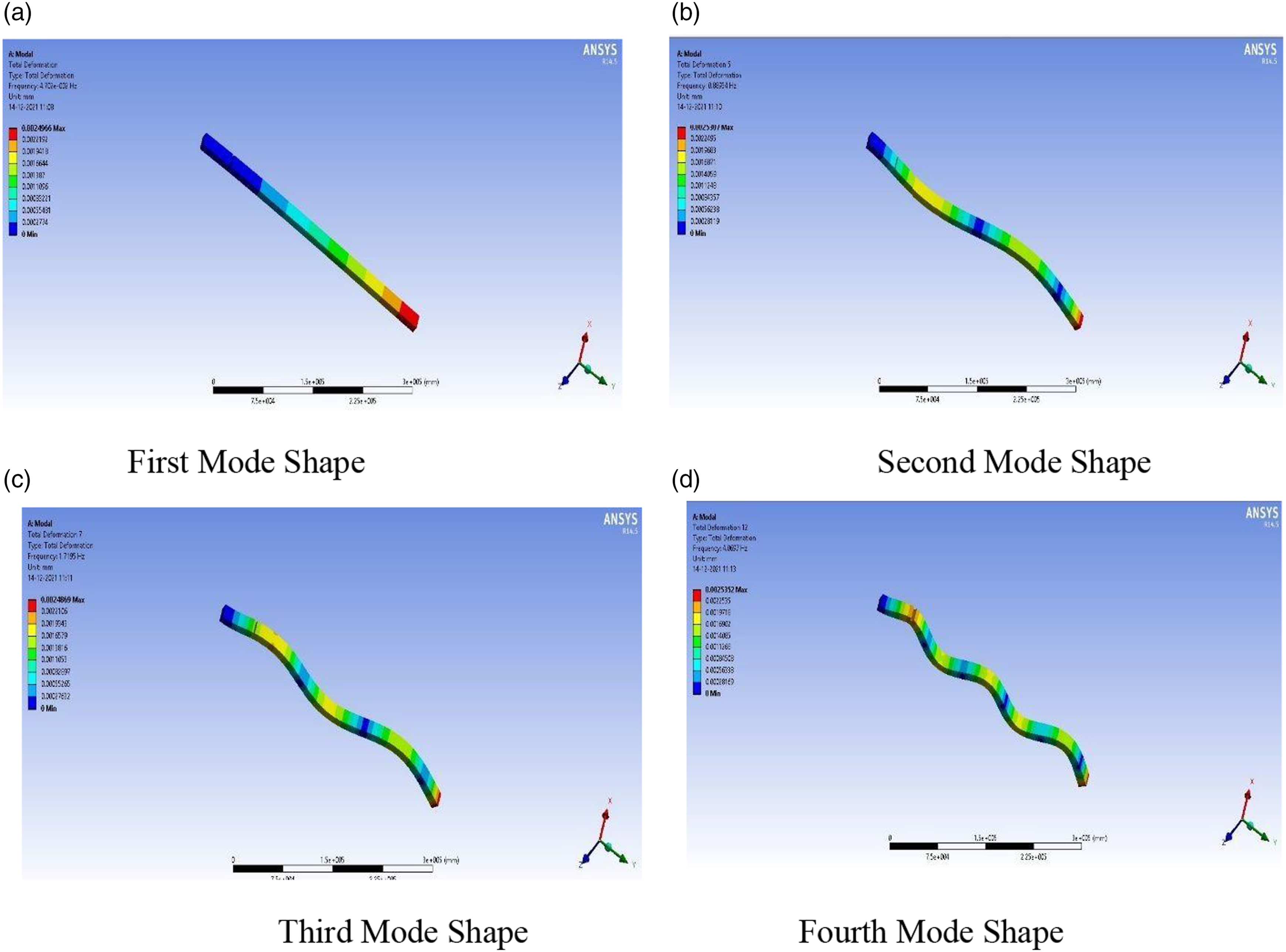
Results and discussion
The deflection in the vibration mode
In the experiment we have the cantilever beam made up of hybrid composite beam which has a density of 2.7 kg/m3, Young Modulus 73 GPa, and average length, width, and thickness of beam are 0.40 m, 0.50 m, and 0.25 m respectively. In SolidWorks analysis, that has close properties to the experimental properties. With the Finite Element programmer ANSYS, a delaminated composite beam is simulated. The layer information of the laminated beam is defined in the shell section, and a 3D layered solid element (Solid 185) is used. In this cross section the report has to give more accuracy of different damage locations. one of the most common disadvantages of natural frequency is when the damage lower is symmetric to the mode shape. The frequency of this mode remains unchanged in this case. The results in this section are more accurate.
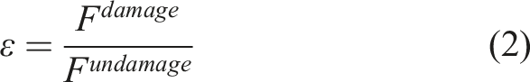
A vibrational behavior of specimen damage and undamaged beam of cantilever beam of relative natural frequency has shown in Figure 5 Flowchart. The relative natural frequency of first four mode shape (i = 1,2,34) is equal to ratio natural frequency of damage beam fi damage to the natural frequency of free undamaged beam fi undamaged. The relative natural frequency for different crack depth (10%, 20%, 30%, 40%, 50%). Flow of relative natural frequency.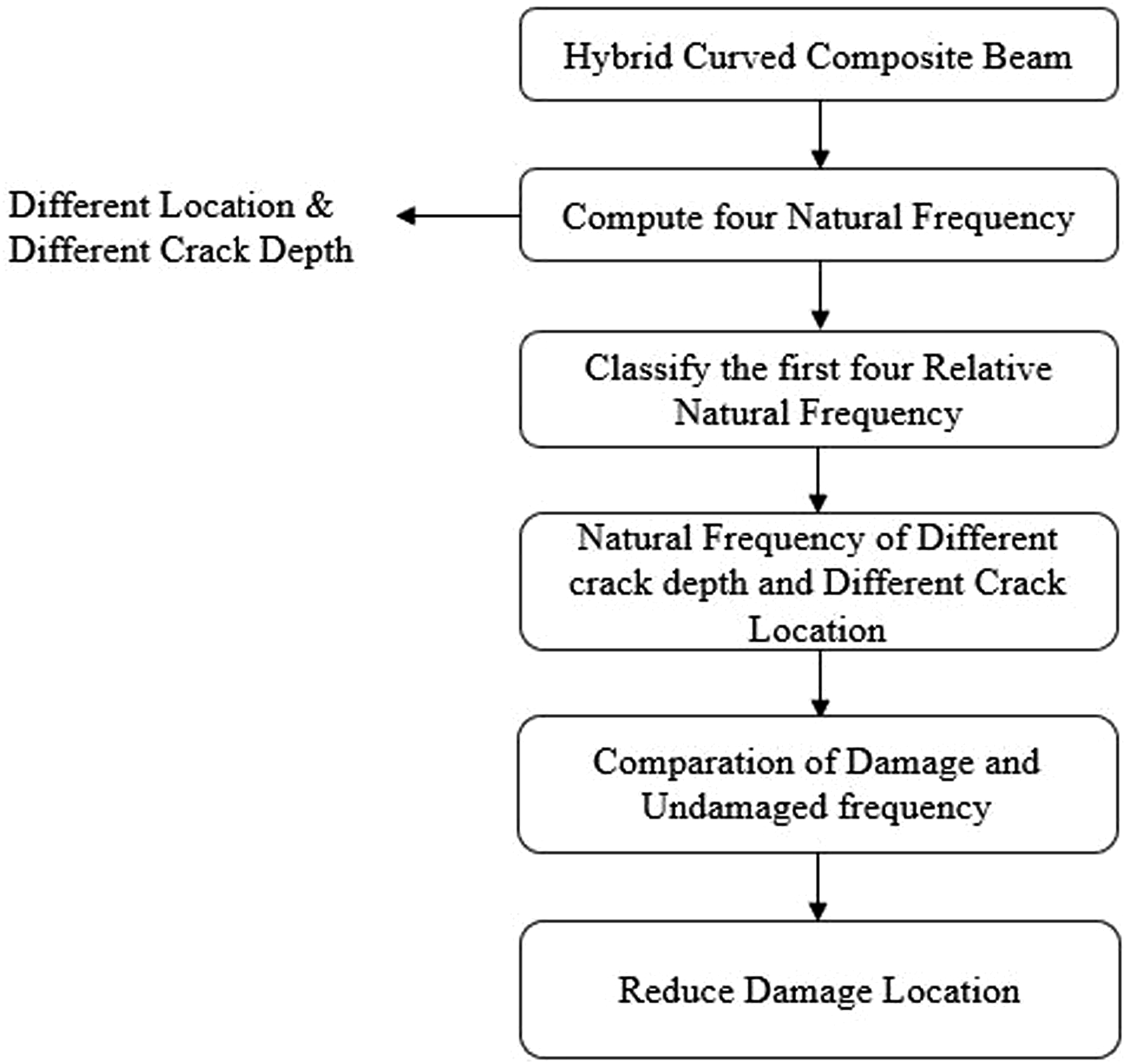
A new method of induced relative natural frequency for different crack and different crack depth. The damage in different crack location in beam has been proposed in the research articles.
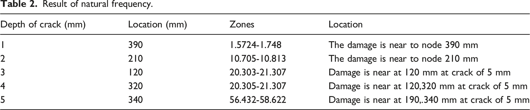
Result of natural frequency.
Stage 1- Give the first four frequency of damage and undamaged structure.
Stage 2- figure out the relative natural frequency
Stage 3- In fine feather induced relative natural frequency differ from undamaged, therefore presence in the damage structure.
Stage 4- verify the normal frequency is equal to 1. The flowchart is prospected the method of natural frequency with different crack location.
Numerical method of solving differential equation or integral equations is known as finite element methods. The method commonly consists of piecewise continuous function to obtain results with different parameter. Finite element methods are applied in ANSYS APDL. The two dimensional applied on Pro-E software, as import in finite elements software. The finite element model has built with different small size meshing and refined mesh near to the damage beam. Totally five different crack and different location of cantilever beam.
The natural frequency varies significantly at necessary crack depths for different crack locations. Furthermore, despite the beam's crack, the natural frequency at nodal sites remains unchanged. Using ANSYS software and experimental investigation, an undamaged fixed beam’s first four natural frequencies are close to theoretical frequencies and are shown in Figure 6. Relative Natural Frequencies for different frack depth and locations (a) First Natural Frequency (b) Second Natural Frequency (c) Third Natural Frequency (d) Fourth Natural Frequency.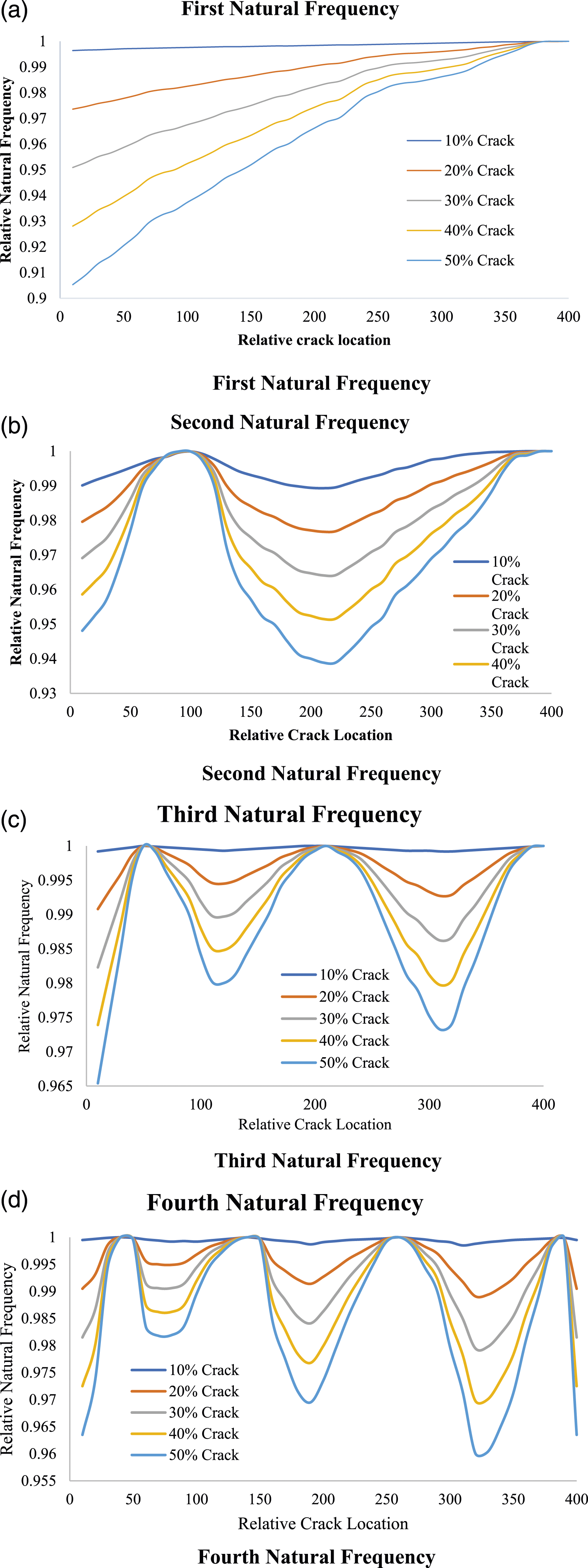
Relative natural frequency of four natural frequency.
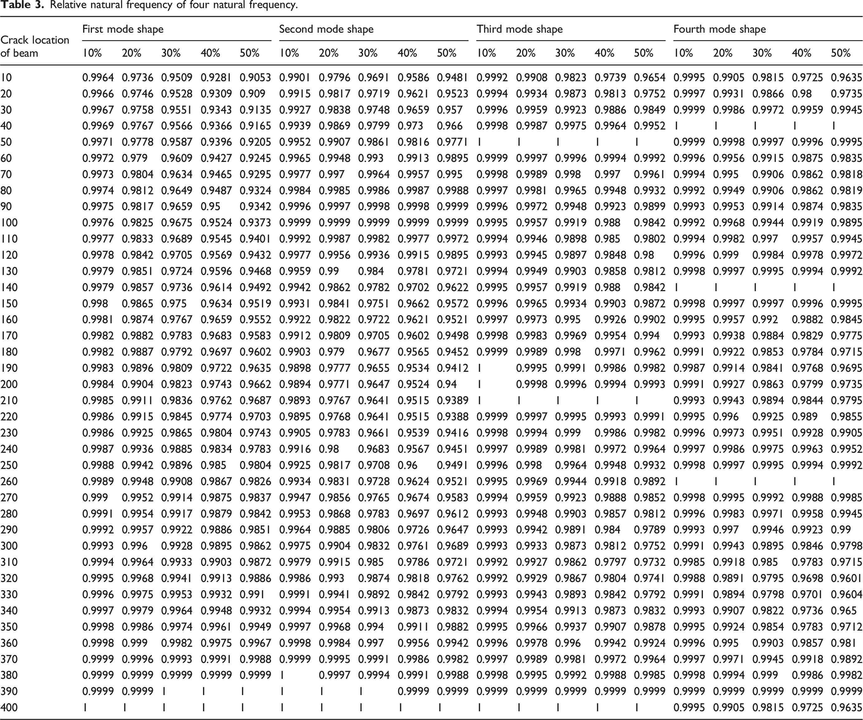
The relationship between these three factors is depicted in Figure 5, along with the effect of fracture location and depth on the natural frequency of a fixed beam. The natural frequency varies with crack location and sharply drops with increasing crack depth. The first three natural frequencies decrease as the crack depth increases from 10% to 50% mm.
Application of ANN
Design of ANN
ANN is most efficient method to analysis the vibration data analysis for severity damage and location detection on cantilever beam. Simulate neural networks has predicated the one hidden layer are describe on MATLAB using neural network tool box. The neural networks present here is used to forecast the location and severity of damage of different crack location. The four-mode shape are exact the location is used predicted the accuracy. The neural network designed to estimated crack and crack locations with has two layer namely hidden layer and output layer has shown in Figure 7. The input layer of 40 location element. The hidden layer has 80 neuron network and output has one neuron, has diagram 6 has describe the hidden layer is a tangent sigmoid function. Structure of artificial neural network.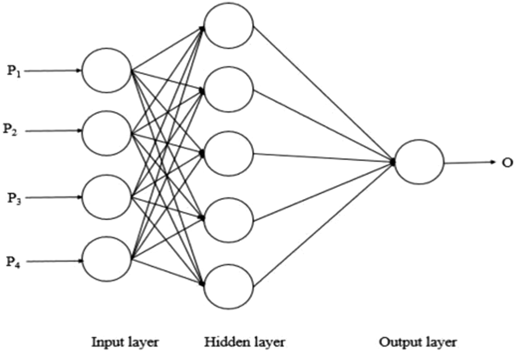
There are totally 6sets (1 undamaged and 5 damage). For damage of 5 crack sample width is 2m and depth of crack (10%, 20%,30%,40%,50% mm). For each Case 40 set of location. Then 800 set of data are used to train the neural network and or testing neural network.
Validation and testing
The back propagation algorithm for supervise learning to provide the input and output analysis. The error difference to be the actual and excepted results is determined. The main aim of back propagation algorithm is lower the error and train data. The training begins with random weight data and motto to adjust error of minimal data. The tangent system input layer are create from hidden layer and output layer for activation of node. The network function is training as follows Back propagation method, Levenberg-marquardt algorithm, gradient decedent moment. Also, MSM (minimum square error) was choose to predict the best result Totally 200 sample out of 20 samples for randomly selected as the training data set. While 10 sample used for validation phase and 10 sample used for training has shown in Figure 8. Percentage of Error in FEA versus ANN.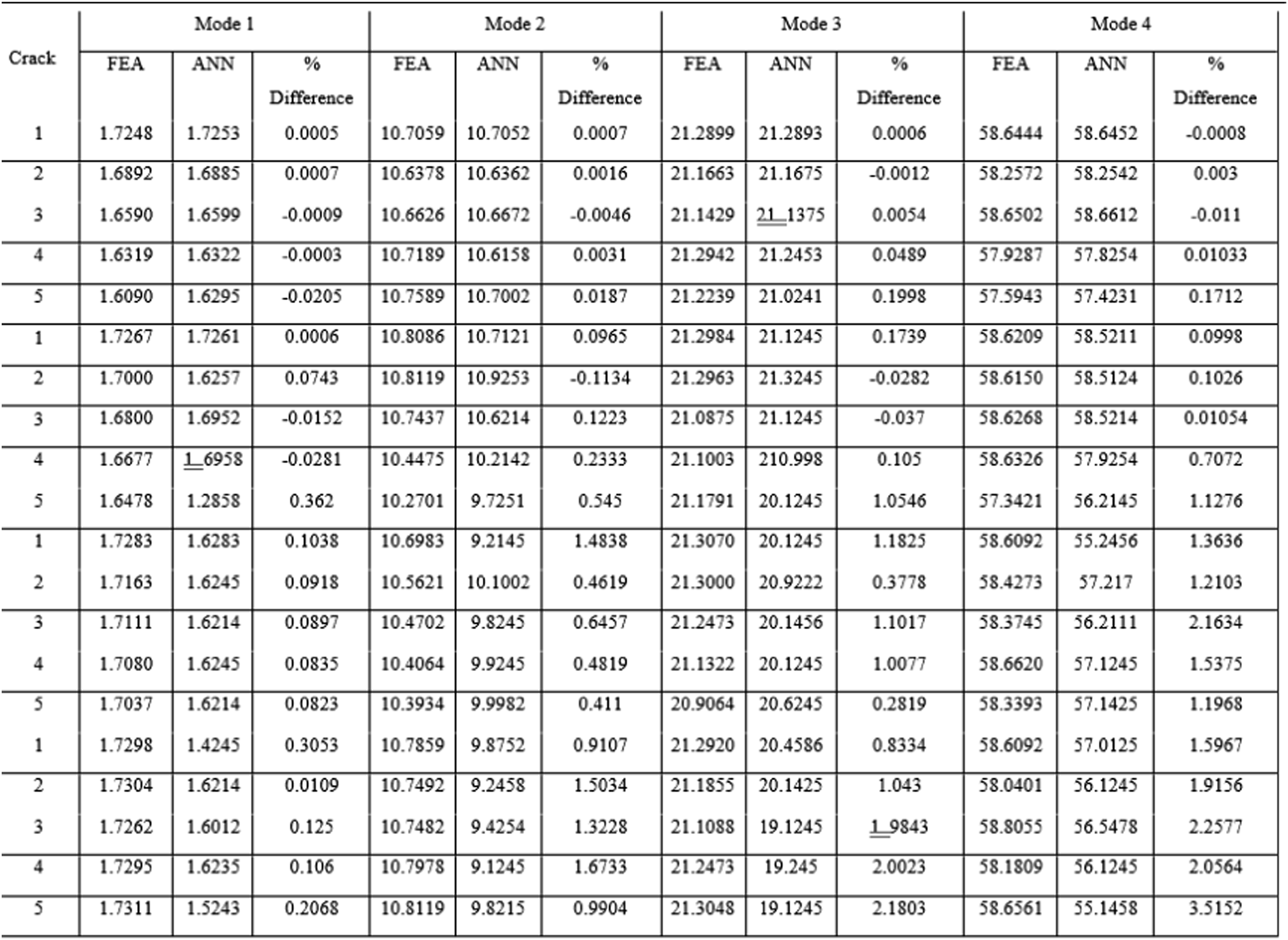
The specifications of the artificial neural network that gave the best performance and used in this study are as follows:
Number of input nodes in the input layer: 3–5 for different cases.
Number of output nodes in the output layer: 1-2.
No of hidden layers: 6,9,18 nodes respectively.
Training algorithm used: back propagation.
Learning Method: supervised learning.
The output of the neural network is the predicted extent of damage in the beam
For different crack location of different combination of input and output are introduced the feed-forward back propagation of ANN for training and validation. The use of artificial neutral network of architecture 4:8:4. The valid finite element of cantilever beam was used with 400m of different 40 location of beam, they introduced the back propagation method of sample generation for analysis using ANN with 800 samples. The model shape of first four mode shape of different crack location and different crack location to applied to calculate the input layer for ANN. Levenberg-Marquardt back propagation method available from NN tool from MATLAB2020a use to train the network.
Testing of ANN
The neural network is accomplished of learning the damage location of crack, severity of the damage to estimate the parameter. The percentage of miscues of both neural network the exact Location in all time crack location. The data of 800 natural frequency of different location and different crack depth is key issues for severity predication of neural network. The training characterizes of ANN input of overall regression plots has shown in Figure 9. Overall Regression plots of training, test, validation, for different crack and different location.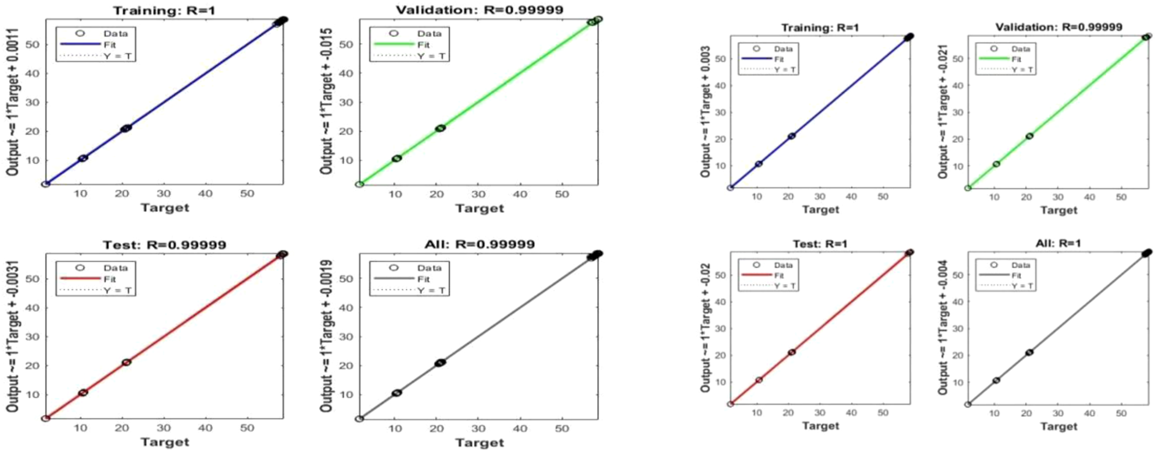
For different mode shape for different crack and location. They observed 1, 0.99,999, 0.99,998, 0.99,997, 0.99,992 are training, validation, testing and overall data. The R value of training testing, validation and overall, of neural network predation. Hence R values of training parameter in current study for better predication. The accuracy of the ANN model and fitting between the measure ANN neural network parameter. The compare between of ANN predication and FEA results. It is an evident that a good ANN with 8 hidden layers for predicate crack and different location parameter. A high degree of accuracy has been observed from the ANN model for both parameters. The Figure 9 has a good agreement was observed between the FEA values use for ANN training. A wide range of cracks and locations can be compare using an ANN model with its predication’s ability. Sensitivity of the model in the terms of Liebenberg-Marquardt back propagation model. The values are observed from the crack 1 mm of location 20 has 0.0005% of difference has low natural frequency. The low level of accuracy of ANN predication has .00,005% to 3.5152%.
The model is performed equally well in predicting has performs of relative natural frequency with different parameter in the range 0.003 to 3.5152%. The maximum difference at mode four of 5 mm crack at the location of 240 mm. However the ANN predication ability of current model is observed to be a quite good model and hence this valuated with ANN function.
Conclusions
For a hybrid curve cantilever beam with a different depth of crack along with different location. The results have demonstrated the classification of the relative natural frequencies of various fracture locations. Based on the results follows,
A beam with a crack has a lower frequency in free vibrations than a beam without a crack. The primary findings indicate that the dynamic behaviour of a fixed beam concerning natural frequencies and mode shapes is influenced by the depth and position of the cracks. Even when a beam cracks, its frequency remains constant at nodal locations. It can be seen from computational and experimental studies that a vibrating structure’s inherent frequency is susceptible to crack influence within a 1%–5% variation.
In conclusion, several factors affect the severity and location prediction of damage in beamlike structures, including the features that are extracted from vibration-based analysis and used as input for ANNs, the amount of noise on these features, the experimental design, the accuracy of the measuring devices in various vibration modes, and the experimental procedure.
ORCID iD
Ashok Ravichandran https://orcid.org/0000-0001-8189-1949
Footnotes
Declaration of conflicting interests
The author(s) declared no potential conflicts of interest with respect to the research, authorship, and/or publication of this article.
Funding
The author(s) received no financial support for the research, authorship, and/or publication of this article.