
Abstract
Gridshell nodes are key elements regarding structural performance, visual appearance and assembly of any gridshell that have been given little attention in recent research. This paper explores aluminium as a material for timber gridshell nodes. First, existing gridshell nodes are categorised regarding bulk materials, gripper types and connection methods and based on this, a set of novel node principles in aluminium are deducted and proposed for a timber gridshell on the geometry of the British Museum Great Court. A finite element analysis is done on the proposals to increase the understanding of the node principles’ structural behaviour and feasibility. Together, the set of node principles, their evaluation and the utilised procedure can provide new options in the future design of gridshells and gridshell nodes.
Introduction
Gridshells are shells where the structural members form a grid of linear members in contrast to a continuous shell surface. Because of their shape, shells transfer forces efficiently, mainly as in-plane compression, tension and shear, rather than out-of-plane bending—resulting in effective material usage. In buildings, the structural form of the shell or gridshell will also define the space with its doubly curved shapes, making them interesting from the architectural point of view. Gridshells can be categorised into three types: bending active, smooth and discrete. 1 Bending active gridshells, such as the Mannheim Multihalle, are constructed from a deformed flat grid of thin membres. Smooth gridshells are constructed from pre-bent or pre-curved members assembled into a smooth surface, like in the Centre Pompidou Metz. Discrete gridshells consist of straight members connected at metal nodes and is the most common type of gridshell. A recent study found that research regarding gridshells is primarily driven by structural engineers and is performed as theoretical studies on specific loads or structural behaviour and form-finding and optimisation of the gridshells global shape and topology. At the same time, little attention is given to the design and development of gridshell nodes. 1
The gridshell nodes are normally constructed in steel regardless of the member material. This paper examines aluminium nodes as an alternative to the typical steel nodes in timber gridshells. Aluminium has several characteristics that could be favourable when used in gridshell nodes. These include high recyclability, corrosion resistance, malleability and low weight.
This paper aims to examine design options for aluminium nodes in timber gridshells enabled by recent developments in digital modelling and fabrication.
Background
From the architectural point of view, designing nodes as visible objects, combining the aspects of structure, assembly, manufacture and appearance, has a large design potential. The term tectonics is often used when discussing architecture in relation to detailing, material and structure. In short, tectonics is about finding the qualities in the materials, structure and connections between materials and tectonics can be found in articulating joints. According to theorist Gottfried Semper, a clear and readable structure can define good spaces, and beauty appears in the articulation of the joints. 2 Theorist Kenneth Frampton sees tectonics as the poetics of construction. 3 Architect and author Edward Ford distinguishes between two types of detailing he terms abstract and articulated. 4 The role of an abstract detail is to hide and diminish the connection, while an articulated detail instead enhances the connection. He argues that although much effort can be put into hiding a detail, there is a way larger potential for conveying a story in articulated details. Gridshells are inherently clear and readable structures, and gridshell nodes are key parts of any gridshell with a huge potential for tectonic articulation. Following the arguments above, this research seeks solutions for gridshell nodes with articulated detailing.
Gridshell nodes for timber gridshells
The nodes in a discrete gridshell, especially with timber members, ensure structural integrity by transferring loads between the members. The nodes play an important role in assembling the gridshell and making the gridshell suitable for prefabrication. Gridshell nodes in discrete gridshells must accommodate small geometry changes between the connecting members. These angles are often referred to as the U-, V- and W-angles,
5
or sometimes as the
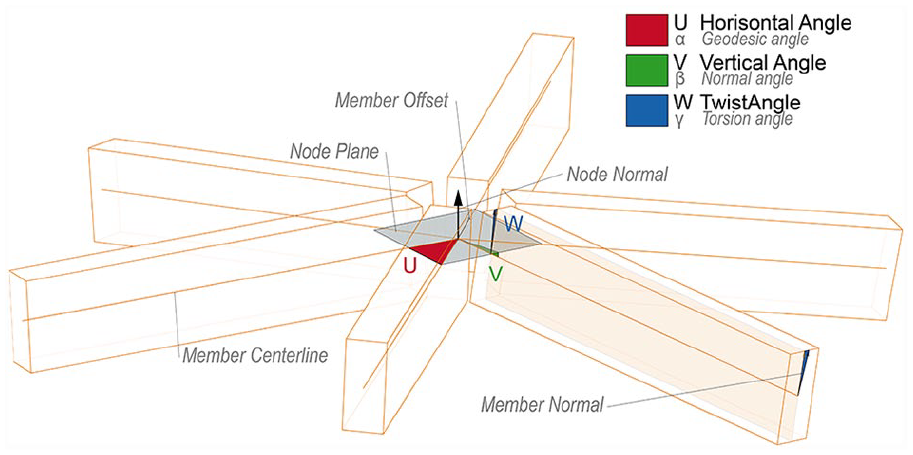
The node angles U, V and W that need to be accommodated by the node or the members in a discrete gridshell.
When selecting nodes for a steel gridshell, manufacturing companies provide a library of pre-designed solutions. Still, for timber gridshells, few solutions exist and the nodes are instead developed specifically for the project. The designer of gridshell nodes needs to combine structural engineering, manufacturing and architectural design aspects. However, the design of nodes is often driven by structural or mechanical engineers. Harris et al. describe how timber engineers B&K Structures with Westmucket and Hawkes (structural consultants) as sub-contractors for the detail-design, designed the nodes for The Pods sports academy. 7 Another example of a timber gridshell with steel nodes is presented by Rabagliati et al. 8 for the Crossrail Place gridshell.
Normally, nodes for timber gridshells are manufactured in steel. The advantages of aluminium are recyclability, corrosion resistance, malleability and low weight. 9 Aluminium generally has lower strength and stiffness than steel, but this can be compensated for with larger cross-sections or smarter material placement. Moreover, there are challenges regarding the fire safety of aluminium because of its lower melting point. Such challenges are also found in steel nodes, and it is assumed that intumescent coatings or active protection systems can solve this. Research from the field of industrial ecology points out that developing products of cast aluminium with a focus on design for disassembly can be especially important in light of the global flow of aluminium as unsorted recycled aluminium can end up as only suitable for casting. 10
Developing nodes as visible objects
Regarding research relevant to gridshell nodes, two common approaches have been identified and are presented here. The first is investigating ways to avoid the node as a visible element in the gridshells. The second is to optimise the shape and topology to reduce the node angles, especially the twist angle, W.
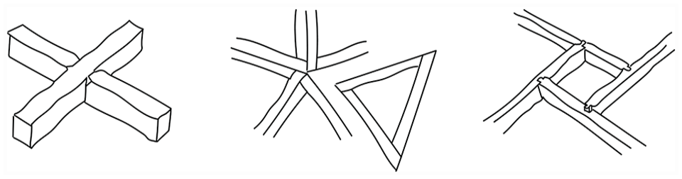
Avoiding the node as a visible object is a common approach in gridshell design and research. The motivation for this can be that gridshell nodes are expensive and complicated or because avoiding the node is an aesthetic choice supporting an architectural idea. Sevtsuk et al. state in their article about the SUTD gridshell that: ‘ [. . .] constructing such joints is costly, requiring strong materials (e.g. steel) and advanced machinery capable of milling custom three-dimensional elements’. 11 Seifi et al. 12 write: ‘It has been reported that structural nodes are one of the most costly parts in constructing 3D structures’. The Centre Pompidou Metz and Swatch Omega Headquarters are recent examples from practice where the idea has been to create a continuous timber lattice with nodes being avoided as visible objects. Instead, the effort has been put into machining, preparing the members and making details for lap joints with hidden screws, as shown in Figure 2. Another approach to avoid the nodes as visible objects, often used in the construction of geodesic domes, is to use a node-free system termed GoodKarma, 13 constructed from preassembled triangles of members, as shown in Figure 2. A third approach for gridshell-like structures without nodes is called reciprocal frames or nexorades, where the connection is placed between the end face and side-face of two members instead of several members meeting in a node, as shown in Figure 2. Examples can be seen in Leopold et al. 14 (p. 45) and Douthe et al. 15
Simplifying the node geometry with optimisation and form-finding methods or improving a given design or designing with bottom-up methods is another common approach to gridshell research. The goals of such simplifications could be to reduce angle variations, 17 create torsion-free meshes (meaning meshes without twist-angle, W) 18 and generate node repetitions/ node congruence. 19 Meshes that can be offset to have planar faces on both offsets are often referred to as face/face offset meshes. Meshes that, in addition, have nodes that meet with an equal vertical angle are called edge offset meshes.19,20 These properties are mostly only possible with quadrilateral panels; however, planar face offsetting is also possible with triangular starting meshes. 21 Bo et al. 22 show how circular arc structures can be a method to create gridshells and space frames with node repletion where the members are made from circle segments. As shown in Figure 3, a ‘caravel mesh’ can provide alternate torsion-free identical 3D nodes and planar nodes with constant angles between members, simplifying the node and providing other benefits. 23 Figure 3 shows a torsion-free node in a quad mesh. Optimising one goal often conflicts with other goals. For example, torsion-free nodes are primarily possible with quad meshes, while triangulated grids are the most structurally efficient. Bottom-up design methods can take care of construction challenges as described by Schling and Barthel. 6 A Chebyshev net on a free-form surface can provide constant member lengths, an asymptotic network on an anticlastic surface can provide constant horizontal angles (U-angle), a geodesic network can provide a constant tilt angle (V-angle) and a principal curvature network can provide constant twist angles (W-angle). Finally, the most common way to simplify the node geometry is probably to construct gridshells as one of several lattice-dome types, including ribbed-, schwedler-, lamella- and diamatic-, or geodesic- as shown in Figure 3.
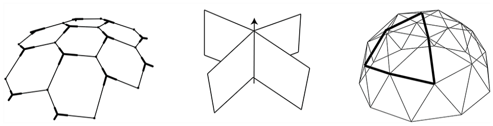
Concepts for simplifying the node geometry. From left: a hexagonal caravel mesh has planar nodes and identical 3D nodes, adapted from Tellier et al. 23 ; A torsion-free node in a quad mesh, adapted from Mesnil et al. 19 and; a geodesic dome has by definition repetition of both nodes and members resulting in, for instance, four node types and five member types.
As opposed to these two common approaches, the main focus of this paper is to develop nodes as visible objects. Research that develops nodes as visible objects also exists, and this research often focuses on possibilities with manufacturing with 3D printing; see de Oliviera et al., 24 Crolla et al. 25 and Seifi et al. 12 Other examples ivestigate an assembly of 3-axis machined plate, like in Lienhard et al. 26 Apart from these recent examples, most development of gridshell nodes as visible objects happens in the industry, like from Lanik Structures 27 and Mero Structures, 28 as formerly pointed out by the author. 1
This study proposes a set of node principles for timber gridshells with aluminium nodes. The nodes are explored for one selected case but should be suitable for other shapes and topologies, including more freely generated shapes and torsion-free and optimised grids. Design for disassembly (Dfd) principles are followed, meaning that glue should be avoided, the number of parts and materials should be minimised and assembly processes should be reversible. The structural performance is evaluated, providing comparable data on the performance of the nodes. In addition to a manufacturing and connection principle, nodes should follow some design intent. The design intent could, for instance, be that the transition should be as smooth as possible to enhance fasteners or to hide or expose the aluminium part.
Method
This paper examines aluminium node principles for use in future timber gridshells. This study defines five steps, resulting in a set of node principles available for anyone working on new, timber gridshells. The first step (3.1) maps a series of existing gridshell nodes and categorises the parts of the nodes into gripper types and bulk materials. The second step (3.2) chooses a case for developing new node geometries. For this, the British Museum Great Court, hypothetically built as a timber gridshell, was selected as a case. The third step (3.3) presents a method to propose novel node principles based on mapping existing nodes and proposes nodes with characteristics not found in the mapping. The fourth (3.4) step is parametric modelling of the node principles with Grasshopper and particularly the plugin Reindeer for handling the data structure necessary for modelling. The fifth step (3.5) adjusts the dimensions of the principles and performs structural analysis on the aluminium node principles based on the member forces from the British Museum Great Court case.
Mapping and categorising existing gridshell nodes
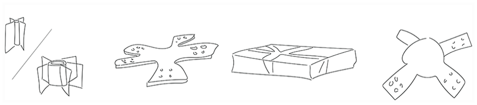
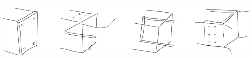
A mapping of existing gridshells and gridshell nodes is performed to provide a basis for this study. This mapping is based on a collection of discrete gridshells, mainly with timber members. Figure 4 shows some examples of existing gridshell nodes. Based on the main parts of the node, three main categories were selected, as shown in Table 1. The categories bulk material, gripper type and connection method were used in the mapping. Bulk material describes the main material type used for the node geometry. Bulk materials can be a cylinder or ring, thin plate, thick plate and ‘monolithic’, the latter meaning some casting or printing where all parts stick together. Figure 5 shows types of bulk materials. The gripper type describes the geometry used when connecting to the timber members. The main types of grippers are end face, horizontal splice, vertical splice and encapsulating. Figure 6 shows the gripper types. Grippers can be made as an extension of the node, which is the most common application, or made separately from the node, requiring another connection between the node and gripper. The connection method category describes how the gripper is connected to the member and is shown in Figure 7. The connection methods are bolt/dowel, threaded rods, screws or glue/weld. Regarding gripper types and connection methods, splices are generally connected using bolts or dowels, and end faces are generally connected using threaded rods. The advantage of an encapsulating gripper is the possibility of fastening using screws.
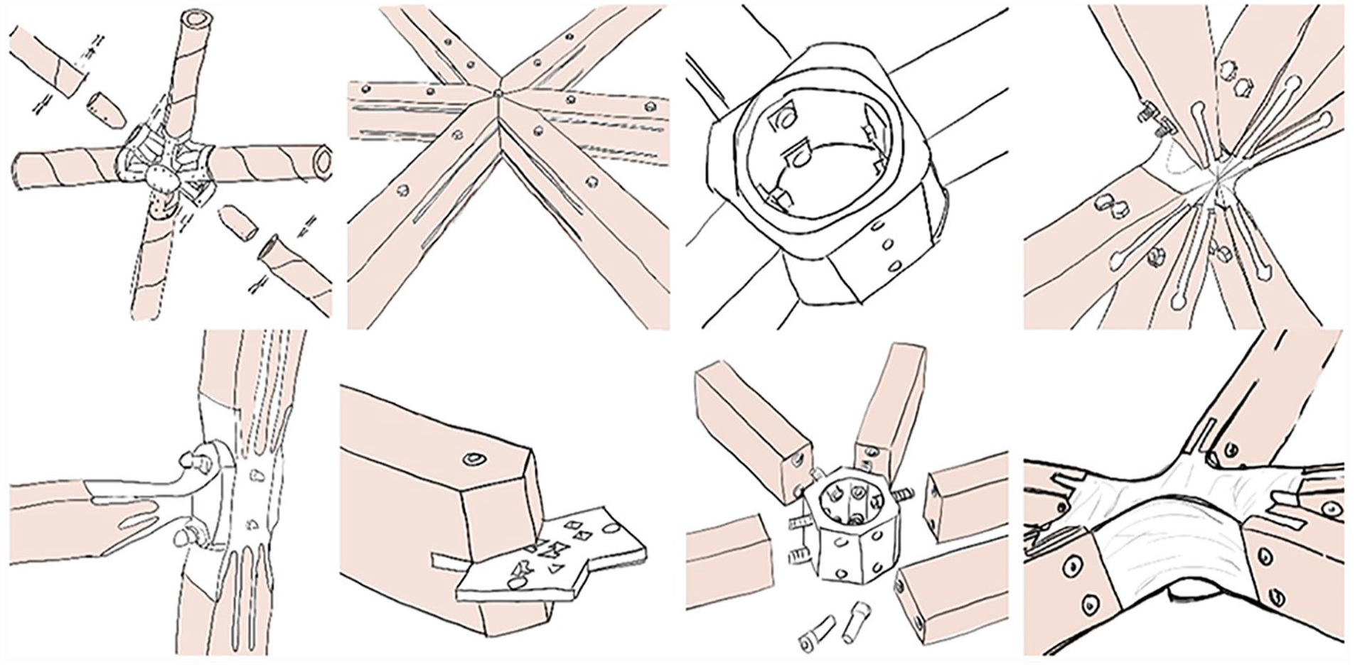
A selection of existing gridshell nodes. From top left: Canopy in Pouilly en Auxois, Dome of Visions 3, Mero ZK and Printshell. From bottom left: IBM Travelling Pavilion, Mero Pavillion, Lanik TSL and Opti Knot Pavillion.
Three main categories of node parts used when examining existing gridshell nodes.
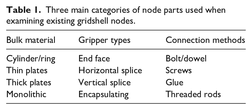
Different bulk materials for nodes. From left: cylinder (solid)/ring (hollow), thin plates, thick plates and monolithic.
Gripper types. From left: End face, horizontal splice, vertical splice and encapsulating.
Different connection methods. From left: bolt/dowel, screw, threaded rod and glue/weld.
Selecting and specifying a case: British Museum Great Court
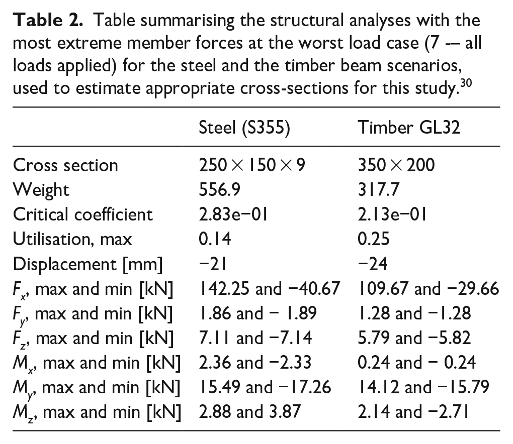
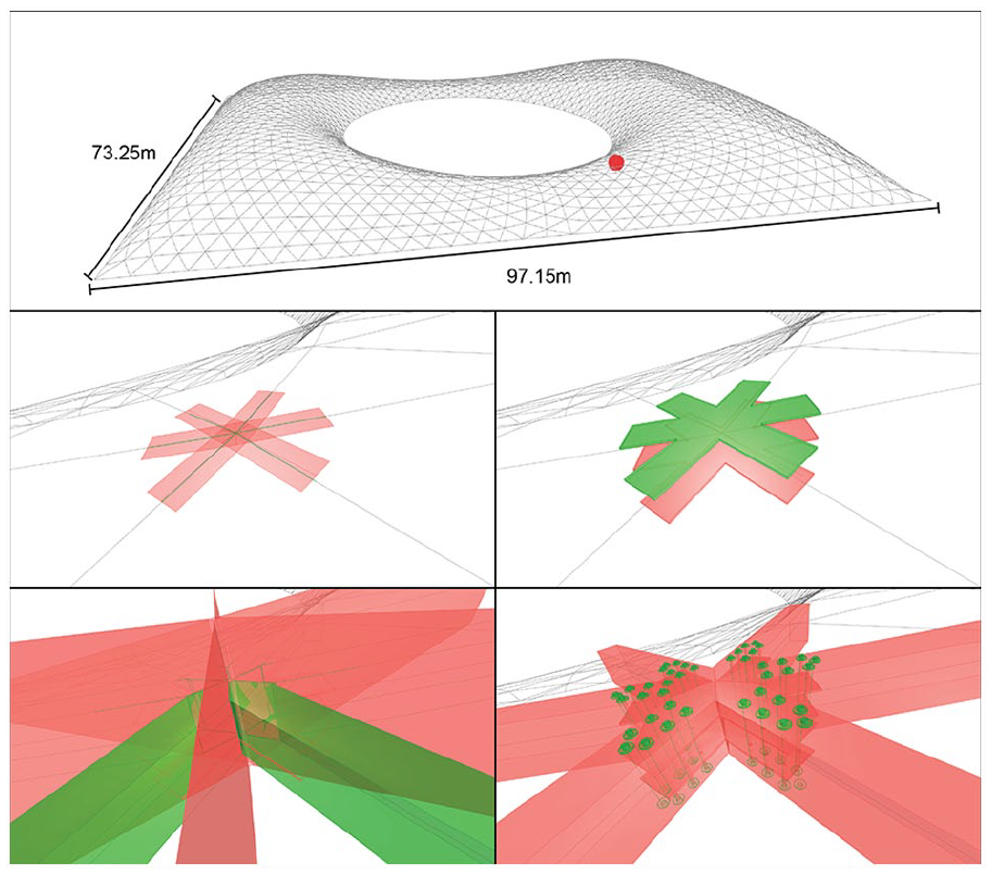
As a case for developing gridshell nodes, the steel gridshell covering the British Museum Great Court 29 by Foster + Partners was selected. There were two reasons for choosing this structure. Firstly, the British Museum Great Court represents a key building in modern architecture and computational geometry. Secondly, it represents a gridshell with typical topology and shape with six members at each node, and differences between all node angles. In this study, this roof geometry was analysed and redesigned as a timber gridshell. The initial mesh geometry can be seen in Figure 11. The analysis has been simplified and is performed as described below. First, the same steel cross-sections, RHS 250 × 150 × 9, were applied to the whole structure instead of the actual cross-section dimensions, which are gradually reduced towards the building’s inner circle (reading room). The existing buildings around the Great Court roof cannot take horizontal thrust, and the supports around the outer square have to be gliding supports. In the actual building, they are supported by a tension ring formed by the members. In the analysis, the boundary conditions were modelled as pinned supports in the inner circle and the other square. Connections at the nodes were also modelled as rigid, which might be a valid assumption for a steel gridshell with welded nodes, but difficult to achieve in a timber gridshell. The loads applied at the nodes include the members’ dead load, the glass roof’s dead load (495.5 N/m2) and snow loads divided into four quadrants (320 N/m2). These loads gave seven load combinations for ULS analysis using Autodesk Robot. As presented in Table 2, GL32 350 × 200 was found to have a similar performance to the steel version. It must be repeated that the analysis is simplified and does no, for example, include dynamic analysis and long-term effects like the relaxation of timber. However, for this study, it was considered sufficient as the main purpose is to get a geometry coupled with member forces. The structural analysis was performed as part of a master thesis in structural engineering. 30 The structural analysis provided the maximum forces in the members presented in Table 2.
Table summarising the structural analyses with the most extreme member forces at the worst load case (7 -– all loads applied) for the steel and the timber beam scenarios, used to estimate appropriate cross-sections for this study. 30
Node principles
Traditional methods for product development usually aim to result in one product, or in this case, one gridshell node. Such a method for product development is exemplified by Takeuchi et al., whose method includes five main steps: modelling, benchmarking, engineering, prototyping and production. 31 A similar procedure was also found in a recent paper for a (reciprocal frame) node development by Castrottio et al. 32 Both studies aim to end up with one final product or design, as explained in the top of Figure 8. The method for proposing new node principles is inspired by set-based concurrent engineering, 33 as shown at the bottom of Figure 8. The idea of set-based concurrent engineering is that instead of going forward with one concept, or several concepts, the set is developed to a level where it can be discussed, and all the concepts in the sets are evaluated with input from different disciplines. The disciplines evaluate whether the compliance is excellent, acceptable, marginal or unacceptable. The sets might undergo several iterations in set-based concurrent engineering, including prototyping. A second principle is to search for intersections between feasible sets, and a third principle is to establish feasibility before commitment. In this study, a set of node principles are developed to a level that includes geometrical feasibility, structural realism and concepts for assembly and manufacturing.
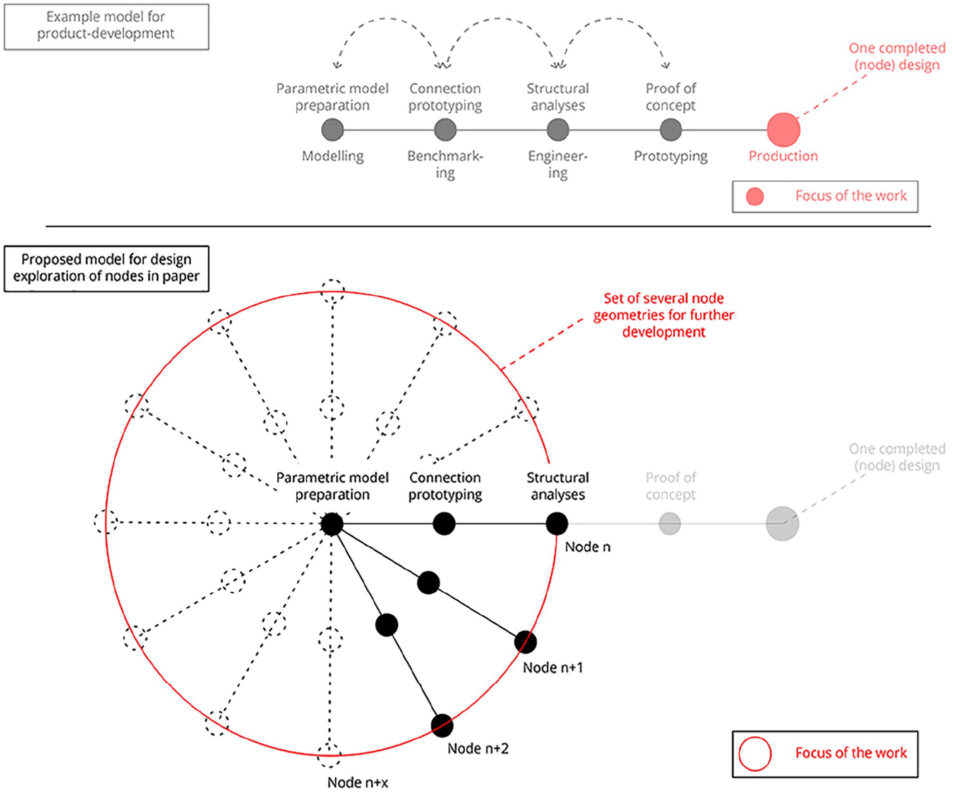
Example of a typical product development model (top) and the proposed model for the development of node principles used in this paper (bottom).
The procedure for proposing node principles is based on a mapping of existing nodes and combinations of characteristics from the mapping. This does not mean that these are the only possible options but suggest a set of systematically developed solutions. Figure 9 shows the two main categories, bulk materials and gripper type, suggested in the study of existing nodes. Combinations of these categories suggest a total of 16 ‘node types’. This paper explores at least one node principle that could fit into each type, although several of the types are not necessarily the most efficient solutions, this is done for the sake of the study. A sketch and a description are made for each potential node principle before the node principle is detailed parametrically to get an accurate geometrical description of the node. The geometrical description is used to provide new knowledge on challenges and opportunities of the concepts that could lead to either rejection or alteration of the concept. Three known gridshell nodes were modelled and adapted to the dimensions of the case project. They are included in the set to compare and test the method’s versatility. The bulk materials are labelled A–D, and gripper types are labelled 1–4, giving each node a prefix like A1 Ring, meaning Pipe/ring (A) as bulk material + End face (4) as gripper type.
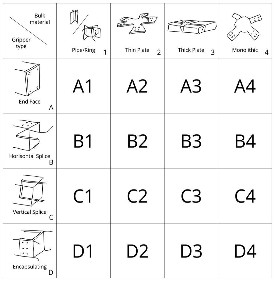
Matrix of options regarding gripper type and bulk material used to deduct new node principles.
Parametric models of the nodes
Regarding tools, this paper uses the framework of Grasshopper and a plugin named Reindeer 34 for the parametric modelling of gridshell nodes. Reindeer adds functionality to Grasshopper by sorting details more efficiently than what is possible in native Grasshopper and was developed with functionality for gridshell detailing in mind. In Reindeer, one first defines all the (timber) members as they will be in the final structure, including the right orientations, alignments and cross-sections. Reindeer can then detect the points, or nodes, where the members meet. With used-defined parameters, one can distinguish between nodes, like foundation node, interior node, a node with larger forces or nodes with more/fewer members connected (singularities). Reindeer then provides a well-organised data structure suitable for detailing these nodes. This study selected a typical node with and index of 500 in the data tree because it demonstrates a typical node with six members and variations in U, V and W angles. The parametric model could, however, handle any of the nodes.
The rest of this subsection presents the parametric modelling procedure of one node, the B3 flat star. A similar procedure is used for modelling all the node principles, which is presented in Section 4. The preparation for the detailing starts with importing the mesh geometry for the roof of the British Museum Great Court into Rhino. The centre lines extracted from the mesh are defined as elements in Reindeer with rectangular cross-sections, 350 × 200. The cross-sections are aligned to the normal direction of the mesh. The elements are assembled first, and then the details are extracted using the Detail Search component. Detail Search provides a data structure for further detailing, but instead of detailing all nodes simultaneously, the node with index 500 is selected from the data tree. The node plane is the average of the incoming members using the PlaneNormal component. Figure 10 shows this initial setup.
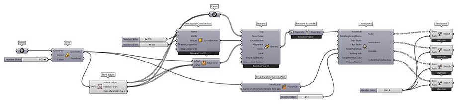
Grasshopper definition of the initial setup for node detailing with Reindeer. The initial mesh contains the great court geometry.
The flat star node consists of two plates cut from a flat sheet inserted into the members at an angle and connected with long bolts inserted from the top. The modelling starts by projecting the member centre lines to the node plane, as shown in Figure 11. They are then offset 100 mm, which is half the cross-section width in both directions. The offsets are lofted to a closed surface. Then the tree, of six branches with one surface in each, is trimmed to allow for a Solid Union into one ‘star’. The star is extruded to 12 mm and moved upwards and downwards in the node plane. A tween, an interpolation, is drawn between each centreline of the members. These curves are then extruded upwards and downwards in the normal direction of the node plane before the extrusions are used for trimming the members. The trimming gives all the members a unique trim and ensures they meet smoothly. Five bolts for each member are added, where the fifth bolt is placed at the end of the plate. The fifth bolt provides a guide for positioning if inserted before assembly. The length of plates (250 mm), the number of plates (2), the thickness (12 mm each) of plates, the number of connecting bolts (6 + 1) and the diameter of bolts (10 mm) are defined as variables. Figure 11 shows the finished geometry. The parametric modelling of the node principles is completed with preparations for the structural analysis. This includes sorting each part of the node in a data tree with branches. In addition, the same data tree is prepared for the direction vectors of the members so that the forces can quickly be added to structural analysis.
Main steps in the parametric modelling of the flat star node. From top left: identifying node 500; project centrelines to node plane and offset; combine, extrude and move the plate geometry; trim the member geometries with the intersecting plane and; add fasteners.
Dimensioning and structural analyses
To better understand the proposed nodes’ structural integrity and feasibility, a finite element analysis is performed for each of the presented node principles. Initially, Eurocode 9 was used to estimate nodal dimensions based on the maximum normal (Fx) forces from Table 3. More complex factors, such as second-order effects and buckling, were disregarded at this stage. This resulted in a minimum cross-sectional area of 4230 mm2. Additionally, the number of fasteners (screws, bolts and dowels) necessary to transfer the present forces between the timber beams and the aluminium node were estimated using the Beaver 35 plugin. For nodes where the connections between timber and aluminium are glued, such as the D2 Glued finger node, sufficient contact area for load transfer was presumed to be satisfactory without any estimations. Using the estimated minimum surface area and the necessary number of connectors, the node principles shown in Figure 12 were modelled.
Member forces for the investigated node at the max moment load case in the global analysis.
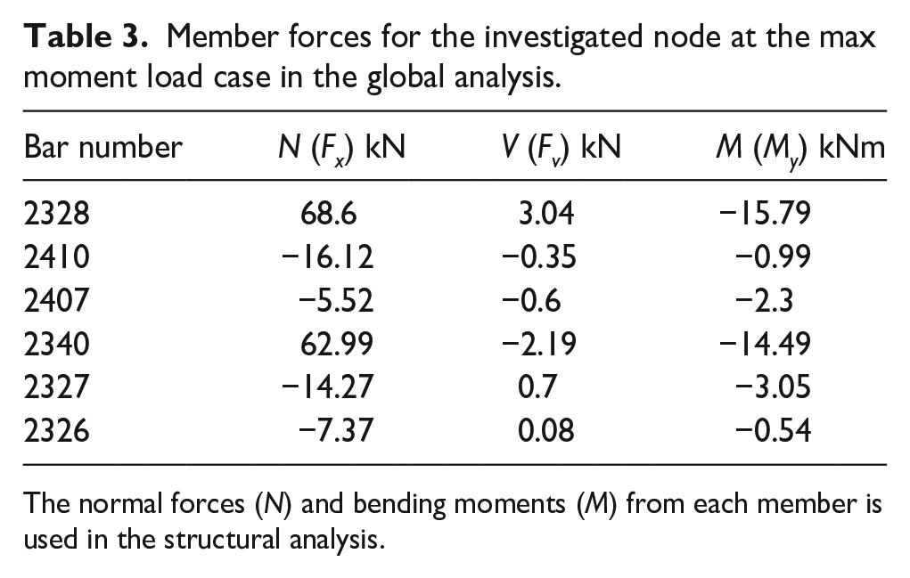
The normal forces (N) and bending moments (M) from each member is used in the structural analysis.
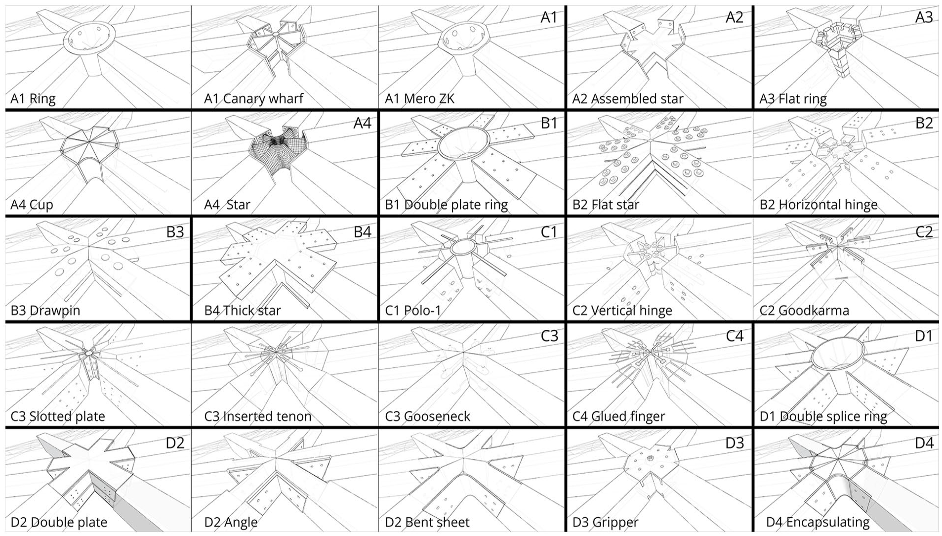
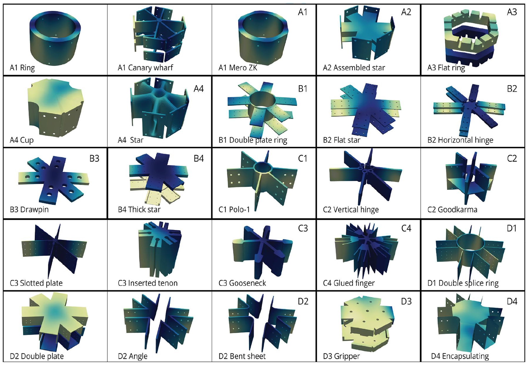
The complete set of node principles proposed and compared in this study.
Each node was then exported from Rhino to ANSYS, where a volumetric finite element analysis was performed. Here, three-dimensional stress distributions and local stress concentrations can be investigated in addition to the beam/shell analysis for the global system. A linear elastic analysis model was set up with the material properties assigned as follows: aluminium nodes were assigned material properties according to EN AC-43300, steel fasteners as structural steel, and the Glulam beams as a homogenous piece of timber with properties corresponding to GL32h. The timber beams were modelled as 1-meter-long elements connecting to each arm of the node with the boundary conditions applied to the beams’ other end to avoid rigid body motions and simulate the relative motion between each member. The contact areas between materials were assumed ‘bonded’ to keep the problem linear. The normal forces and moments from Table 3 were then applied to the beam elements to allow recreation of the load transfer from beam to node through the fasteners. The results of the analyses are presented in Section 4. Although the analysis is simplified, it gives an overview of how the different connections behave structurally.
Results
The result of this paper is the execution of the design procedure and the set of evaluated node principles. This section presents the node principles developed during this study and the results from the structural analyses. Figure 12 All shows the geometries for each node principle and their corresponding names.
The node principles explained
Each node principle is described regarding its concepts for the accommodation of angles, manufacturing, assembly and connection to timber elements. The inspiration or background for the principle is also described when it is relevant.
A1 Ring comprises a thick ring with machined holes. The timber members are machined to accommodate the V- and W-angles instead of the ring to allow for a thinner and lighter ring. The position of the holes accommodates the U-angles, and threaded rods in the members are connected to the node with nuts.
A1 Canary Wharf node is constructed from an assembly of welded thin plates. It is an adaptation of the node at the Crossrail Place at Canary Wharf in London. 8 The plates form a cross-shaped section that connects to the end face plates and a tube in the centre. The members have steel plates at the end face with threads that allow bolting to the node. The node accommodates the U, V and W angles, which are uniquely machined and assembled. Connections are moment resistant and designed to hold the weight of one member during assembly without additional scaffolding.
A1 Mero ZK is shaped like a conventional steel node design and is adapted from Mero ZK. 5 It is made from a ring with machined sides and machined holes. The machining of the side accommodates the U, V and W angles. The members have two threaded rods inserted, connected to the node using nuts.
A2 Assembled star is constructed by two planar horizontal splices welded to flange plates functioning as the ‘step’ of an I-profile. End face plates with holes connecting to the timber are welded to the ends of the I-profile. The node accommodates the U, V and W angles, and threaded rods connect the members to the node.
A3 Flat ring uses screwed-in threaded rods for connecting the timber to the nodes. They are screwed in with an inclination angle of 10° at the member’s top and bottom. The flat ring node consists of one solid part with machined slots for the rods. The rings have two planar sides and can be machined with three-axis machining. They are assembled by sliding the member with preassembled rods in the member’s plane and then tightening a set of nuts to the rods. The node handles the U, V and W angles, but since there are two rings, the influence of the tilt (V) and twist (W) are greatly reduced.
A4 Cup consists of a cup-shaped node with an even thickness on all parts. The node is monolithic and produced with patternless casting or milled from a thick plate. The node connects to the members using double-threaded rods assembled with nuts to the node. The U, V and W angles are all handled by the node.
A4 Star is a monolithic star-shaped node with a hollow core to reduce weight. Production is done using patternless casting or cast in 3D printed moulds. The node handles U-, V- and W-angles, and the assembly is done by fastening the double-threaded rods with bolts to the node.
B1 Double plate ring is made from a large ring and two welded horizontal splices. The splices are welded to the ring and have unique positioning that accommodates the U, V and W angles. The members have machined grooves on top and bottom to position the splices and are connected using screws.
B2 Flat star is made from thin machined plates which are flat and can be machined with a three-axis CNC. The members are individually machined with chamfering, which allows for smooth intersections and slots for the plates. The node accommodates the U-angle, whereas the tilted slots in the timber accomodate the V- and W-angles. The two node plates are fastened with bolts going through the whole member.
B2 Horizontal hinge uses hinges to accommodate the U-angle. The hinges sit at identical nodes with an even 60° distribution. Attached to the hinge are two horizontal plates pre-bolted into horizontal slits in the timber members. The members with the groove accommodate the V- and W- angles. The advantage of this node is that all parts can be mass-produced identically except the members, which are all unique.
B3 Drawpin draws inspiration from a timber tenon joint locked with a pin. The node is similar to the Flat star node but is made from one thick plate connected with two larger aluminium pins. The U angle is accommodated by the machined thin plate in the node’s centre, whereas the V and W angles are accommodated by the angle of the slot in the timber.
B4 Thick star consists of two thick plates machined to fit the members. It is assembled from the top and below, and the two plates are connected to the members with screws. The node accommodates the U, V and W angles.
C1 Polo-1 represents a typical node design: a cylinder with vertical grippers. The design is adapted from Mero’s Polo-1. 5 The grippers are welded to the cylinder to accommodate the U-angle, and a twist accommodates the W-angle. The gripper plates are also made uniquely to accommodate the V-angle, and the members thus have identical slits. The node is connected to the members using bolts.
C2 Vertical hinge uses a hinge to accommodate the U-angle. The hinges sit at identical nodes with an even 60° distribution. Attached to the hinge is a pre-bolted vertical plate in a tilted slit in the timber members. The slits in the member with the positioning of the holes accommodate the V-angle and the angle of the slot for the W-angle. The advantage of this node is that all parts can be mass-produced identically, except the members, which are all uniquely machined.
C2 Good karma is a node accommodating for a preassembly of triangles. The members are made of half the total member width, and the node is used as the corner of each triangle. The node includes holes for bolting together the triangles, and the members are further fixed with screws along the members. All parts are unique. However, the advantage of this system is prefabrication with fast and precise assembly.
C3 Slotted plate uses in-slotted plates as the connector to the timber. The plate is prefabricated and connected using dowels to the timber and bolts to the node. The node is machined from a thick plate and is planar on the top and bottom, slightly shorter than the in-slotted plates. The node accommodates all U, V and W angles.
C3 Inserted tenon uses glued-in tenons to the timber fastening to the node. The node caters for all the U, V and W angles and is machined from a thick plate, and timber members are chamfered to reduce the node size. Assembly is done by sliding the members with the tenons into the node. Positioning in a vertical direction is ensured as the tenon is lower than the node, and fastening is done with an expanding pin at the node.
C3 Gooseneck is inspired by the gooseneck timber joint. The male part of the gooseneck is the node, machined from thick plates and the female part is machined in timber. It is lapped to provide positioning and better moment resistance. The uniquely machined node accommodates the U, V and W-angles and is planar on one side for simpler manufacture. The members are chamfered to allow for a tight assembly and smaller nodes. The node assembly is done by sliding the members to the gooseneck in the member plane. A screw secures the vertical position of the node.
C4 Glued finger is inspired by the nodes at the IBM Travelling Pavilion. 36 The node is a machined plate core with additional vertical cast grippers glued to the timber members. The glued grippers are identical, whereas the uniquely machined nodes have one planar side and can be made with five-axis machining from a thick plate. The grippers are pre-glued to the timber and assembled to the node by sliding into a wedge-shaped dovetail. After sliding in place, it is locked to the node with a bolt. The custom-made node takes up the U, V and W angles.
D1 Double splice ring is a ring with two welded vertical splices. It represents a solution common in steel gridshells but not in timber gridshells. The two splices are welded to unique positions, thus accommodating the U, V and W angles. The members have milled grooves for positioning the splices and connecting with dowels. However, screws would also be possible.
D2 Double plate comprises two welded assemblies of thin plates that wrap around the members. Members are machined uniquely to position the nodes. The members connect to the nodes with screws. The nodes have one planar side and accommodate the U-angle. The machining in the members accommodates the V and W angles.
D2 Angle is made of angles that connect to the sides of two and two members. The angles are sorted in groups, in this case, 50° and 90°, to fit as close as possible but still allow for mass production of the angles. The angles are made by welding together two thin plates with pre-drilled holes. Unique machining of the members takes up the U, V and W angles. Slots for positioning the angles are machined to ensure they can be inserted on-site and fit even though the angles are identical.
D2 Bent sheet uses thin plates to connect two members. The timber members are grooved on each side to ensure the part’s positioning, which is connected with screws. The sheets are made from thin plates and are machined uniquely with three-axis milling. The sheets are pre-bent to the required angle, and the U, V and W angles are handled by the deformation of the uniquely machined plates.
D3 Gripper consists of two machined thick plates. The plates are planar on both sides and attach to the timber with a lap for gripping the timber members. Unique machining in the timber positions the lap and accommodates the V and W angles, whereas the node accommodates the U-angle. Assembly of the node is done by sliding the members onto the bottom part and fixing them with a screw. The top part of the node is inserted after all members are positioned and is fixed using a screw to the timber and a bolt between the node parts.
D4 Encapsulating covers the member on three sides and connects to the member with screws. The nodes are unique, while the members have simple machined slots for the node. The node has a hollow core and an even material thickness. The U, V and W angles are by the node. The assembly is done by sliding the member in its vertical direction to the grippers and is connected with screws.
Evaulation of the node principles
The structural analyses were performed on all node principles and are presented with a focus on von Mises stresses and displacements. Figures 13 and 14 show each node’s stress- and displacement plots. Here, the nodes’ behaviour under the applied load case can be investigated in detail.
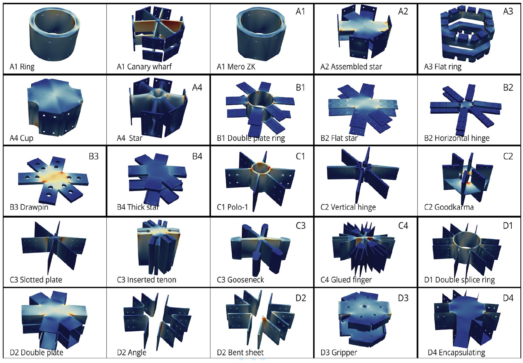
Stress distribution of the von mises stresses from the structural analysis of all the node principles.
Displacement distributions from the structural analysis of all the node principles.
In general, most node principles had a maximum utilisation of around 100%, meaning that their dimensions are approximately correct for the applied loading. Only the D1 Double splice ring utilisation (150%) and displacement (9.93 mm), and C3 Slotted plate utilisation (132%) and displacement (12.64 mm) had performances indicating that the selected dimensions of the node were insufficient. All of the remaining node principles showed potential within initial dimensions and designs.
The implications of the structural analysis on each node are further presented as heatmap plots showing the mean value of different key metrics according to the categories from Figure 9. Figures 15 to 18 show the plots comparing the performance between combinations of bulk materials and gripper types regarding utilisation of connectors and nodes, total weight and displacement. Figure 15 shows the maximum utilisation of the types as a percentage of the materials’ yield stress. General observations are high utilisation in the bulk materials pipe/ring and lower utilisation in the thick plates. Regarding grippers, the lowest utilisation was observed for encapsulating combined with thin or thick plates. Pipe/ring combined with end faces also yielded low utilisation.
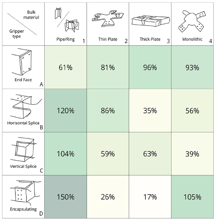
Heatmap plot of the maximum utilisation of the aluminium node for each combination of bulk material and gripper type. Utilisation above 100% is considered material yielding, but is in this study used to indicate the efficienty of the principles.
Heatmap plot of the average utilisation for each combination of bulk material and gripper type. In general, a low average utilisation combined with high local stresses indicate nodes with an ineffective material distribution throughout the node.
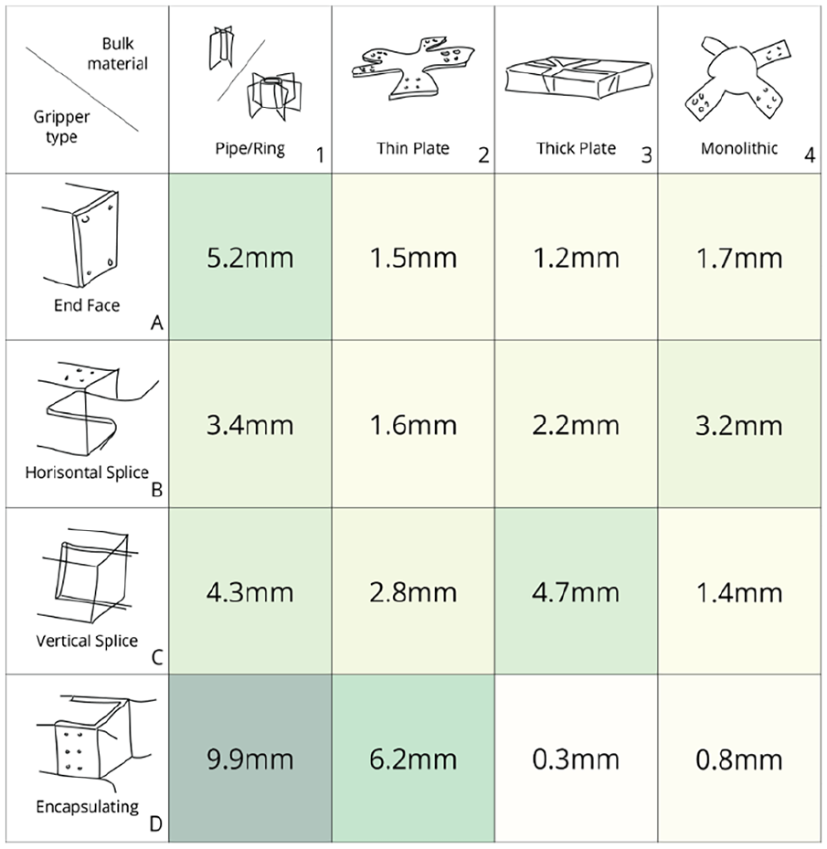
Heatmap plot of the displacement (mm) for each combination of bulk material and gripper type.
Heatmap plot of the total weight (kg) of the aluminium nodes and steel connectors for each combination of bulk material and gripper type.
Displacements of the different node types are shown in Figure 17. The Pipe/Ring nodes had the highest average displacements and the nodes with thick plate and monolithic geometries had the smallest displacements. In more detail, A4 Canary Wharf was the principle with the largest total displacement (14.54 mm), followed by C3 Slotted plate (12.6 mm); both of these have a thin unsupported vertical plate which is subjected to large local stresses, causing bending moments about the weak axis for the asymmetric load.
In addition to knowing the capacity of the principles, another interesting aspect is the average stress level throughout the node. As depicted in Figure 16, the upper left diagonal in the matrix had a higher level of average utilisation in the nodes, with the A3 Flat ring as the highest together with the D1 Double splice ring having values of 9%. Conversely, the D3 Gripper had the lowest average utilisation of 2%, together with B4 Monolithic. Here, the vertical slot at each arm of the node, combined with the thick plates being connected at the top and bottom of the beam provided a connection well suited to the present load cases; the The B4 thick star worked similarly except for the lack of vertical slots. Additionally, the nodes in D2, Angle and Bent sheet, had a low maximum and average utilisation due to the primary load transfer happening between the timber beams themselves, with the aluminium part of the connection working mainly to hold the pieces in place.
The weight of the nodes are estimated by combining the volume of the geometries and the corresponding density of aluminium (for the nodes) and steel (for the connectors) as shown in Table 4. The lightest principles were the A4 Cup (28.5 kg), A4 Canary Wharf (28.8 kg), B2 Flat star (28.9 kg), A2 Assembled star (32.0 kg), C3 Slotted plate (33.1 kg) and D3 Gripper (33.4 kg). Among these, D3 Gripper and A2 Assembled star were among the best performing regarding deflections and stress levels. Looking at the total weight, the lightest were D2 Double plate (39.3 kg), D3 Gripper (40.3 kg), C3 Slotted plate (44.0 kg), C2 Goodkarma (46.5 kg) and C3 Gooseneck (50.9 kg). Figure 18 shows the total weight for each of the categories. End face (A) and some encapsulating (D) stand out as the lightest types, whereas monolithic (4) with horizontal (B) and vertical (C) splices stand out as the heaviest.
Material properties for the finite element analysis in Ansys. Aluminium for the node, steel for screws, bolts and dowels and glulam for timber beams. 37
Discussion
When evaluating the performance of a gridshell node, several aspects should be included. Factors such as manufacturing, assembly and structural behaviour have been presented in previous sections and are further discussed below. It is generally favourable with a node design where most of the material contributes to its load-carrying abilities and stiffness, analogous to industrial steel beam profiles. Regarding characteristics, the nodes with an End Face gripper type and Pipe/Ring geometry seem to outperform the others. This finding is strengthened by the fact that these node principles are commonly used and were derived from realised projects. Canary Wharf, Mero ZK and Polo-1 fall within this group.
Depending on the global shape and topology, the need for resisting bending moments in the plane of the node may vary. In gridshells with a triangular configuration of the elements, the in-plane stability and stiffness are ensured, similar to a truss structure. In such cases, the Pipe/Ring nodes, which have a thin vertical plate without much resistance for the in-plane moments, are suitable. In contrast, the thin and thick plates have their strong axis in-plane and would be more suitable in cases where the chance of in-plane bending is large. However, for out-of-plane bending, the plate geometries, such as the B3 Drawpin, benefit from having a large distance between the horizontal plates to ensure a greater resistance to out-of-plane moments. The hinged nodes, B2 Horizontal hinge and C2 Vertical hinge should be assumed to have no in-plane rotational stiffness in the connection between beams and node, and should consequently only be used for triangulated gridshells.
Regarding manufacturing, some principles would need unique prefabrication of both nodes and members, whilst others are simpler. The principles considered the easiest to manufacture is the A1 Ring node, where the main challenge is unique cuts of the members, C1 Polo-1, a geometry with few parts and simple member machining and B2 Flat star, B3 Drawpin and B4 Thick star, which can be machined directly from a sheet. For the assembly, some nodes consist of several parts and are hard to position, whereas others have few parts and are easier to assemble. The principles considered easiest to assemble are C3 Gooseneck, C3 Inserted tenon and C4 Glued finger, where all parts are prefabricated and slide in position, and B4 Thick star, D1 Double Splice Ring, D2 Double plate and D4 Encapsulating, which consist of two parts that also handle positioning.
There are two benefits of having nodes with low weight. Firstly, the costs are directly related to the price per kilo of metal; secondly, heavy nodes are unsuitable for manual lifting, which has implications at many building project stages. Most nodes have a total weight ranging between 55–80 kg, while the monolithic nodes with vertical and horizontal splices are considerably heavier, with values of 105.5 and 122.4 kg. When looking at the node part, most are below or around 50 kg, a common limitation for manual lifting. Achieving these low weights is expected to be one of the advantages of aluminium nodes over steel.
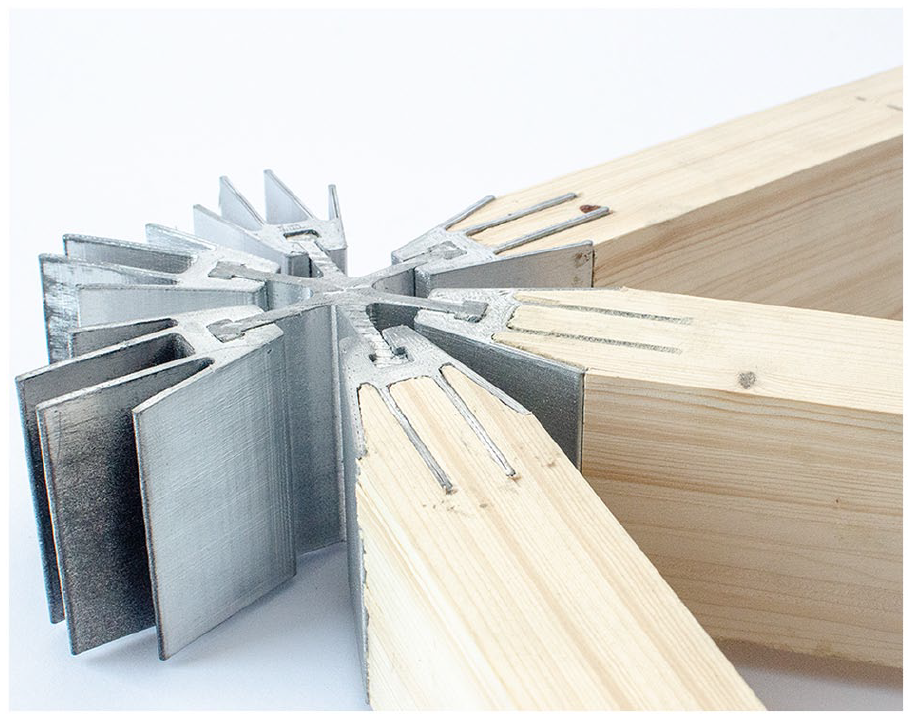
For illustrative purposes, a selection of node principles was 3D printed in 1:5 scale as depicted in Figures 19 to 24. Although neither using the same production method nor being true to size, the prototypes provide useful insights into how the nodes function as structural and design elements.
3D printed prototype of A4 Star.
3D printed prototype of A2 Assembled star.
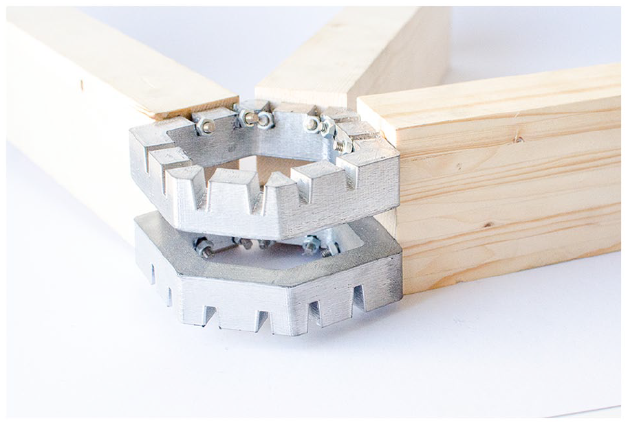
3D printed prototype of A3 Flat ring.
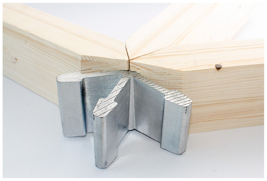
3D printed prototype of C3 Gooseneck.
3D printed prototype of C4 Glued finger.
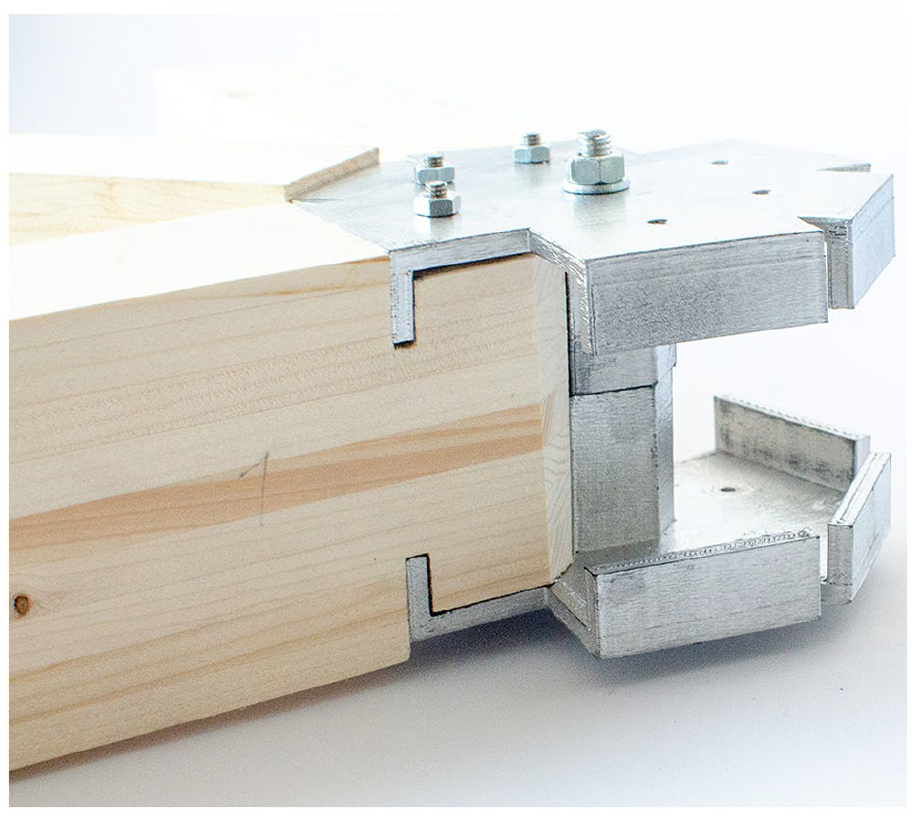
3D printed prototype of D3 Gripper.
Conclusion
This paper has presented a procedure for parametric modelling of timber gridshell nodes in aluminium and evaluated a set of novel node principles. The contribution of this paper is the set of node principles and the procedure for conceptual node design and evaluation. The set of node principles can serve as a future library for designing gridshell nodes. A classification system of node parts has been used to propose novel node principles and evaluate each category’s performance. Some of the principles were proposed to fill all categories for the sake of the study, like the B4 Thick star, which performs reasonably but is much heavier than the others. Some of the nodes could fit into other categories, and many more node principles can be proposed by following the same scheme.
The evaluation of the principles has shown advantages in some of the node types. The nodes with end face grippers all have low maximum utilisation, low total weight, high average utilisation and low displacements. Moreover, D2 Double plate and D3 Gripper showed particular potential, with low maximum utilisation total weight and should be examined further.
The study has highlighted the potential of aluminium in gridshell nodes. Particularly the light weight of the nodes can be advantageous in assembly. The structural evaluations indicate that aluminium is a suitable material for gridshell nodes. The authors believe that a library of nodes should be shared to promote the design of gridshells. At this stage, all the node principles from the study are made available on the following Speckle stream, including displacement plots, stress plots and the British Museum Great Court geometry. https://speckle.xyz/streams/7da24aeba4https://speckle.xyz/streams/7da24aeba4. Further work could include adjustments to the node principles based on the analyses and prototyping. Studies of the rotational stiffness, different cross-sections and experimental testing could further improve the node principles and the usability of the set (Figure 25).
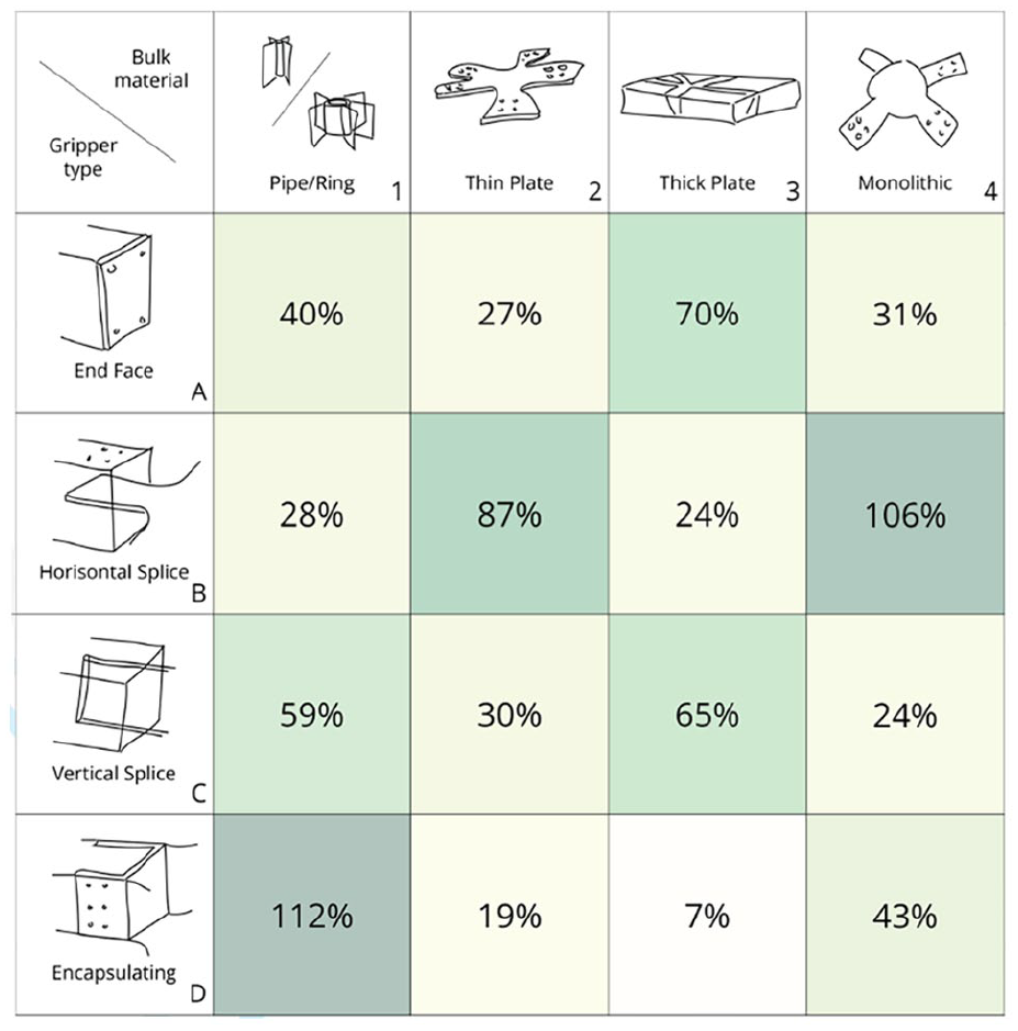
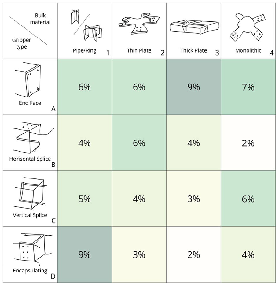
Heatmap plot of the maximum utilisation of the steel connectors for each combination of bulk material and gripper type. Utilisation above 100% is considered material yielding, and is in this study used to indicate the efficienty of the principles.
Footnotes
Acknowledgements
The authors acknowledge the valuable input from the NTNU Aluminium Product Innovation Center (NAPIC) during the development of this project and the effort of architecture student Karl Aksel Jermstad in making prototypes.
Declaration of conflicting interests
The author(s) declared no potential conflicts of interest with respect to the research, authorship, and/or publication of this article.
Funding
The author(s) disclosed receipt of the following financial support for the research, authorship, and/or publication of this article: This research received no specific grant from any funding agency in the public, commercial or not-for-profit sectors. However, the authors appreciate the scholarship provided by the Scandinavia Japan Sasakawa Foundation, which provided the opportunity to bring the research and manuscript preparation to Kyoto University.