
Abstract
Elastic kinetic structures are a recent approach to design transformable structures. Their transformation is based on elastic bending, that is compliant component behavior of structural members. This principle can be used to realize transformable structures with a stable deployment process. Regardless of a stable transformation, elastic kinetic structures are prone to static and dynamic loads due to their lightweight design. However, most of current research on these structures solely focuses on the principles of transformation. This paper proposes a concept for an active hybrid roof structure with a transformation based on elastic kinetics and rigid-body motion. The concept exhibits a stable structural deployment and active control components to counteract static and dynamic disturbances. Furthermore, this paper includes the realization and experimental evaluation of a mid-scale prototype structure.
Keywords
Introduction
Active structures for shape adaptation target to increase flexibility and usability of buildings. Shape adaptation refers to the change of structural geometry/configuration. Examples are transformable structures, such as retractable roofs, movable bridges, and adaptable facade systems. They utilize active control components to realize a usually slow transformation. These active control components are (1) sensors to monitor the structure’s current state, (2) control algorithm utilizing sensor data to decide for suitable interventions in case of external events, and (3) actuators to carry out controller demands. The presence of these three components characterizes active structures and differentiates them from conventional passive structures.1,2
Unlike conventional structures, active structures for shape adaptation adapt to external conditions, like weather events, passing ships, as well as to user requirements, such as sun protection or air conditioning. Thus, they are multi-functional, a property, which makes them superior for many applications and can contribute to saving resources. 3
Common design approaches for shape adaptation utilize rigid elements sliding on rails, folding or rotating around fixed axes, like lift and bascule bridges and retractable dome structures. 4 However, these constructions are not lightweight in general. In contrast, membrane structures are especially suitable for transformability due to their lightness and flexibility, but they are only stable in their final deployed state.4–6
Elastic kinetic structures are an alternative lightweight approach for shape adaptation. 7 Their transformation is based on elastic bending/compliant component behavior. Through the bending of structural members, elastic energy can be stored in a structure. When these forces are balanced in the system, they can contribute to a structural stiffening. This principle can be used to stabilize transformation processes. Current investigations on elastic kinetic structures primarily focus on the principles of structural motion. However, the fact that these structures are highly sensitive to static and dynamic loads due to their lightweight design, is rarely addressed.
The first main contribution of this paper is the development of an active hybrid roof structure concept with (1) stable structural deployment and (2) adaptation for static and dynamic loads. The concept consists of multiple elastic kinetic segments, which are radially arranged. Forces are entirely balanced using a tension and compression ring system. This combination of structural members subjected to elastic bending and normal forces generates a hybrid structure. By reducing the tension ring diameter, the elastic kinetic segments can be transformed simultaneously. The transformation is based on elastic kinetic and rigid-body motion. It is stable during deployment and in any deployment state. In order to react to static and dynamic loads, which may disturb the deployment process, the concept considers active control components for static and dynamic load adaptation of the elastic kinetic segments.
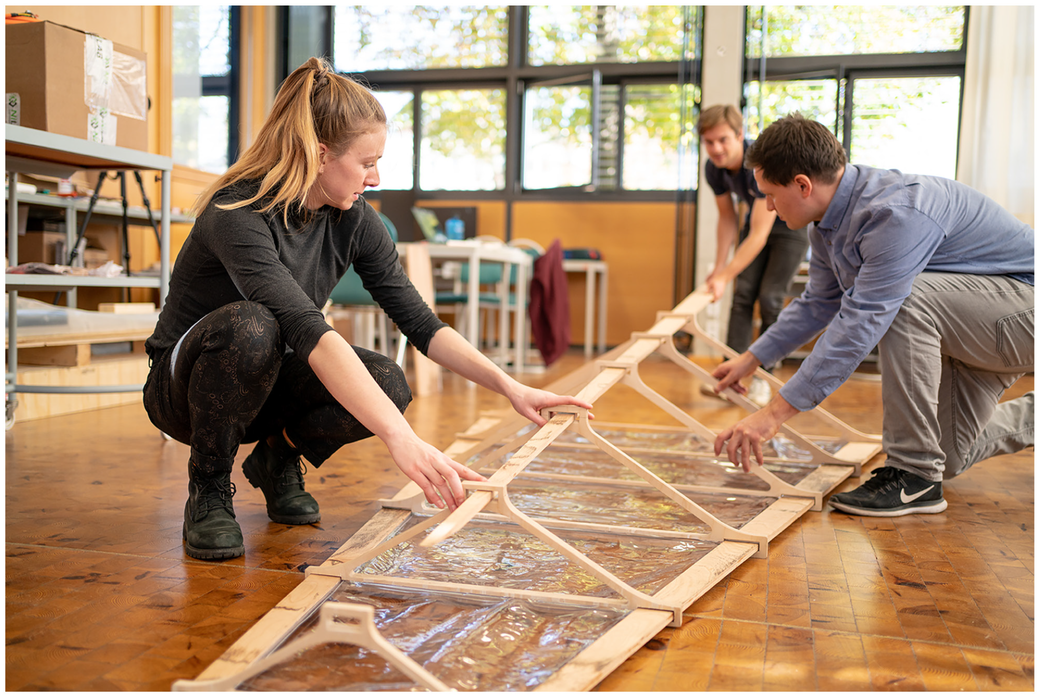
The second main contribution of this paper is the realization and experimental validation of one elastic kinetic segment from the structural concept. This mid-scale prototype was recently built at the Chair of Hybrid Structures – Structural Concrete at the BTU Cottbus-Senftenberg (Figure 1). The developed concept and the realized prototype are the result of preliminary investigated and developed methods at the Chair in the field of active structures.8–12 In the first place the prototype is realized to test and experimentally validate these methods in a laboratory environment.
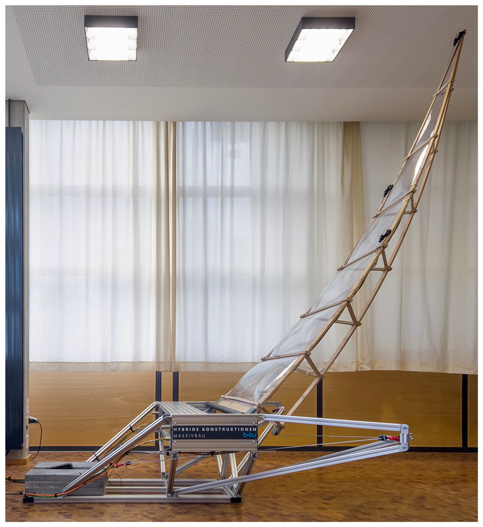
Active hybrid roof structure prototype at the Chair of Hybrid Structures – Structural Concrete at the BTU Cottbus-Senftenberg.
The paper is structured as follows: In the beginning, the basic concepts are introduced, which characterize active hybrid structures. Subsequently, the developed roof structure prototype is described in detail, which includes its concept, design, modeling, dimensioning, and construction. Finally, experimental investigations for static and dynamic validation of a derived finite element model are carried out. The paper concludes with a discussion and gives an outlook on future experimental investigations.
Basic concepts for active hybrid structures
As stated in the introduction, in contrast to conventional passive structures, active structures exhibit active control components. In literature, the term adaptive is also widely used for this type of structures. However, we will use the term active throughout this paper. Active structures can be categorized according to their application, there are active structures for shape adaptation and for static and dynamic adaptation.1,2
Hybrid structures can be defined in various ways, but the characteristic feature in all cases is the combination of different materials, elements, functions and technologies, which lead to an increase in efficiency on several design levels such as the material, cross-sectional, load-bearing, or structural level. 13 Specifically, in our proposed active hybrid roof structure concept, we combine structural members, which are elastically bend with structural members, which are subjected to normal forces only to balance forces.
In the following we will give an overview on lightweight design principles, which are crucial when designing transformable structures. Furthermore, we will give an overview on shape adaptation based on elastic kinetics and on static and dynamic adaption. At the end of this section, suitable materials for elastic kinetic structures are discussed.
Lightweight design principles
When designing a lightweight structure, there are basically three different categories, which in principle can also be combined with each other: lightweight construction materials, lightweight structural systems, and design of lightweight structures. 14
According to the principle of lightweight construction materials, the weight reduction of a structure is achieved by the material used. Thereby, the material is evaluated by considering various ratios of material properties, depending on the specific application. Common ratios are the ratio of strength, stiffness, or elongation to specific weight and the breaking length. 15 Suitable materials for the application in active hybrid structures and their evaluation by means of a material property ratio are described in more detail in subsection Materialization.
The objective of lightweight structural systems is the integration of additional functionalities into lightweight components in order to obtain an overall lighter system. In addition to their load-bearing function, lightweight structural systems can also have room- and space-enclosing or insulating properties, for example pneumatic structures. 15
The design of lightweight structures aims at finding optimal load transfer mechanisms on a constrained design space. Within this structural optimization, there are several methods for finding an optimal geometry for a lightweight structure, which includes the optimization of shape and topology.16–19 Often these methods generate optimal solutions regarding a so called form-defining load case, which in classical structural optimization is usually the dead load. However, for ultra lightweight structures the influence of external static and dynamic loads increases, which questions the consideration of a single form-defining load case within structural optimization. 15 For this reason, active structures with static and dynamic load adaptation and their appropriate design are currently investigated to further shift the boundaries (subsection Static and dynamic adaptation).
Shape adaptation based on elastic kinetics
A recent approach for transformable structures is that of elastic kinetic structures. 7 These structures have the special feature that their motion is based on flexurally elastic respectively compliant component behavior, without the use of additional hinges. Being able to create visually appealing and elegant transformation shapes from initially simple straight rods or flat plates represents one advantage from the field of elastic bending. 20 The inspiration for elastic kinetic/compliant structures is often taken from nature, as described by Howell, 21 Schleicher, 22 or Bögle et al. 23 Concepts for applications range from adaptive facade systems through pavilions to convertible stadium roofs.8,24–26
Regarding the structural behavior, the radii of curvature are directly related to the bending stiffness of the components. The smaller this stiffness of the structural elements, the greater the curvature, which can be realized. Thereby it is highly significant, that the induced bending stresses must not exceed the elastic limit, as plastification causes permanent deformation, thus avoiding the possibility of a complete elastic reversible transformation.
Static and dynamic adaptation
Active structures for static and dynamic adaptation target to improve the load-bearing behavior and serviceability of structures. For static loads, internal forces are redirected to avoid stress peaks and to generate a uniform stress state. For dynamic loads, the resulting structural vibrations are actively damped. This way, with the same or less material usage, the load-bearing capacity, the serviceability and the reaction to extreme events can be improved, which enables to build lighter structures and to save resources. 27
Many researchers have been investigating the reduction of structural motion due to strong winds and earthquakes using passive, semi-active, and active control systems. For a comprehensive overview of structural control, which mainly refers to dynamic adaptation, see for example, Housner et al. 28 and Saaed et al. 29
Recent investigations of lightweight but non-transformable structures yet again proofed the effectiveness of static and dynamic adaptation.30–36
Teuffel 30 developed a load path management method, that allows the design of minimum weight adaptive truss structures. Within this method, load transfer mechanisms and deformation behavior under variable loads can be optimized.
Bleicher 31 experimentally investigated active vibration control to counteract pedestrian-induced vibrations of a CFRP stress ribbon footbridge. Using lightweight pneumatic muscle actuators integrated into the handrail, a multi-modal vibration damping was achieved.
Neuhäuser et al. 32 showed the effectiveness of static and dynamic load adaptation for the example of a lightweight timber shell structure with three actuated supports. In the case of asymmetric loads, the support displacements are actively adjusted, such that stress peaks inside the shell structure are reduced.
A small-scale adaptive arch structure with actuated supports for static adaptation was realized and investigated by van Bommel et al. 33 By rotation of the supports, internal stress states were actively manipulated and maximum stresses were reduced.
Senatore et al. 35 focused on the design of adaptive structures with static adaptation. Thereby the savings in whole-life energy consumption of adaptive structures in comparison to passive structures are discussed. Experimental investigations and validations were conducted on an adaptive cantilever truss structure with 10 actuators integrated.
Weidner et al. 34 and Wagner et al. 36 investigated the principles of actuation and actuator placement for adaptive truss structures on the example of a high-rise building.
The investigations and realized prototypes shown before proof the effectiveness of static and dynamic adaptation. The targeted elastic kinetic structures, which were described in the previous subsection, are highly sensitive to static and dynamic loads due to their lightweight design. However, current investigations on elastic kinetic structures primarily focus on the principles of structural motion, that is the transformation rather than on principles of static and dynamic load adaptation. Consequently, an adaption for these loads seems to be reasonable for a reliable operation of elastic kinetics under real-world conditions.
Recently, we investigated the potential of linear parameter-varying models to describe the dynamic behavior of lightweight elastic kinetic structures. 9 In the scope of a simulation study with a simplified 2D structure, the applicability of the modeling framework was shown. Based on the derived dynamic model an active vibration control of multiple modes during the structure’s transformation was designed and validated in simulation.10,11
Materialization
For the realization of the aspired active hybrid structures, the use of materials with a high ratio of bending strength to bending modulus is essential. 37 Materials, which suit these requirements are primarily fiber-reinforced plastics (FRPs), but also wood and engineered timber like bamboo and beech laminated veneer lumber (Beech LVL) seem to be adequate. A comparison of these materials is given in Table 1.
Comparison of materials by means of bending strength
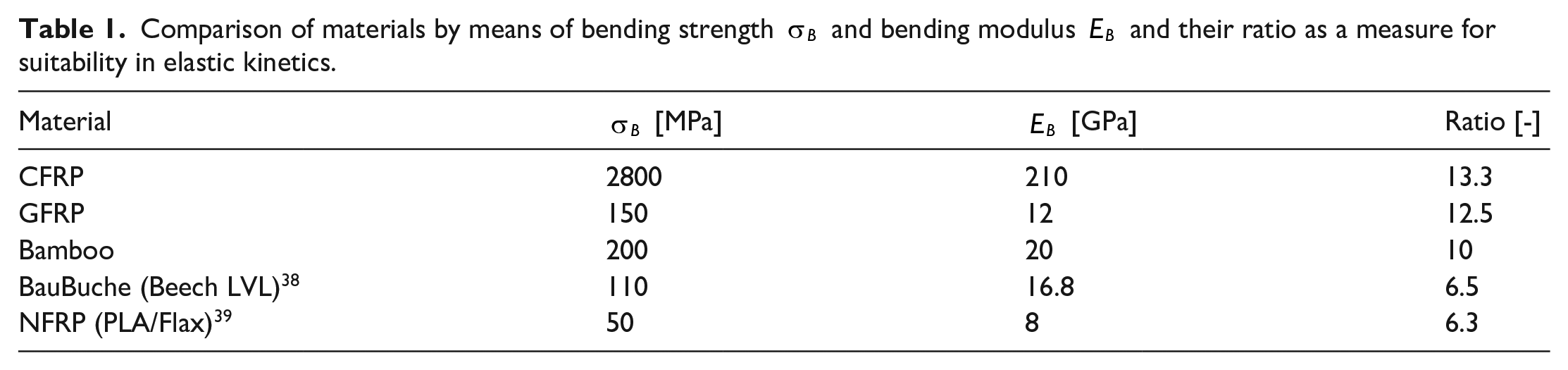
The fundamental advantage of FRPs is, that their material properties can be individually adjusted up to a certain degree, based on fiber matrix combinations and fiber orientations. For this reason, there is a suitable FRP for various applications and requirements. 14 However, the most widely used glass and carbon fibers have disadvantages when it comes to sustainability. They are not renewable materials and their production, especially of carbon fibers, is energy-intensive. Moreover, the problem of recycling GFRPs and CFRPs is not fully solved yet. Mostly they are downcycled at the end of their usage. 40
More sustainable FRPs with natural fibers (NFRPs) are the focus of research. Their main advantages are low cost and low embodied energy in comparison with glass and carbon fibers. Moreover, they exhibit low density and relatively high strength. When the natural fibers, mostly from flax, hemp, or sisal, are embedded into a bio-based polymer matrix they are even 100% bio-degradable. 41 However, the quality of natural fibers is strongly influenced by their growing environment, which leads to variation in mechanical properties. By regulation of growth conditions and optimization of the fiber extraction process, quality problems can be diminished. 42
Most applications utilizing NFRPs so far do not primarily focus on a load-bearing function, but rather on non- or semi-load-bearing, such as for roof panels or facades. 42
An example, where NFRP with flax and hemp fibers was used as a primary load-bearing material, is the prototyping pedestrian bridge built in 2016 at the Campus of TU Eindhoven in the Netherlands. 43
Another material, which can be considered highly suitable for elastic kinetics is bamboo. Compared to other lumbers, it has a very high bending strength. However, its material properties are highly dependent on its habitat. Depending among others on the climate, soil condition, location, and age of harvest, the material parameters vary significantly. 44
In contrast, BauBuche, which is a beech laminated veneer lumber made by Pollmeier Massivholz GmbH, 38 is manufactured in a highly technological process and shows few material imperfections, which results in a rather homogeneous distribution of stresses in the material. It can be processed and reworked precisely.
A previously conducted 3-point bending test of BauBuche GL75 at BTU even revealed a bending strength of 137 MPa and a bending modulus of 12 GPa. This results in a ratio of strength to stiffness larger than 11, which is in between bamboo and GFRP. However, it is noted that BauBuche is suitable for indoor or covered applications only (service class 1/2). As this restriction does not play a decisive role in the realization of our indoor prototype, BauBuche GL75 will be used as the primary material.
Prototype concept
In the previous chapter, basic elements of active hybrid structures were discussed. Based on these elements, a structural concept for a convertible roof is derived in the following, which aims to combine elastic kinetics with lightweight design principles and adaptivity.
The following requirements are stated for the derivation of the roof’s structural concept:
(1) Stable transformation based on the principle of elastic kinetics
(2) Multi-functional upper closure skin for various buildings by using a structural concept with entirely balanced forces, thus, the impact on any possible building is the structure’s self weight only
(3) Realization of a maximum transformation range, for example, defined by rotation angle of the structural members
(4) Active control system for the adaptation against static and dynamic loads during transformation as well as for discrete transformation states
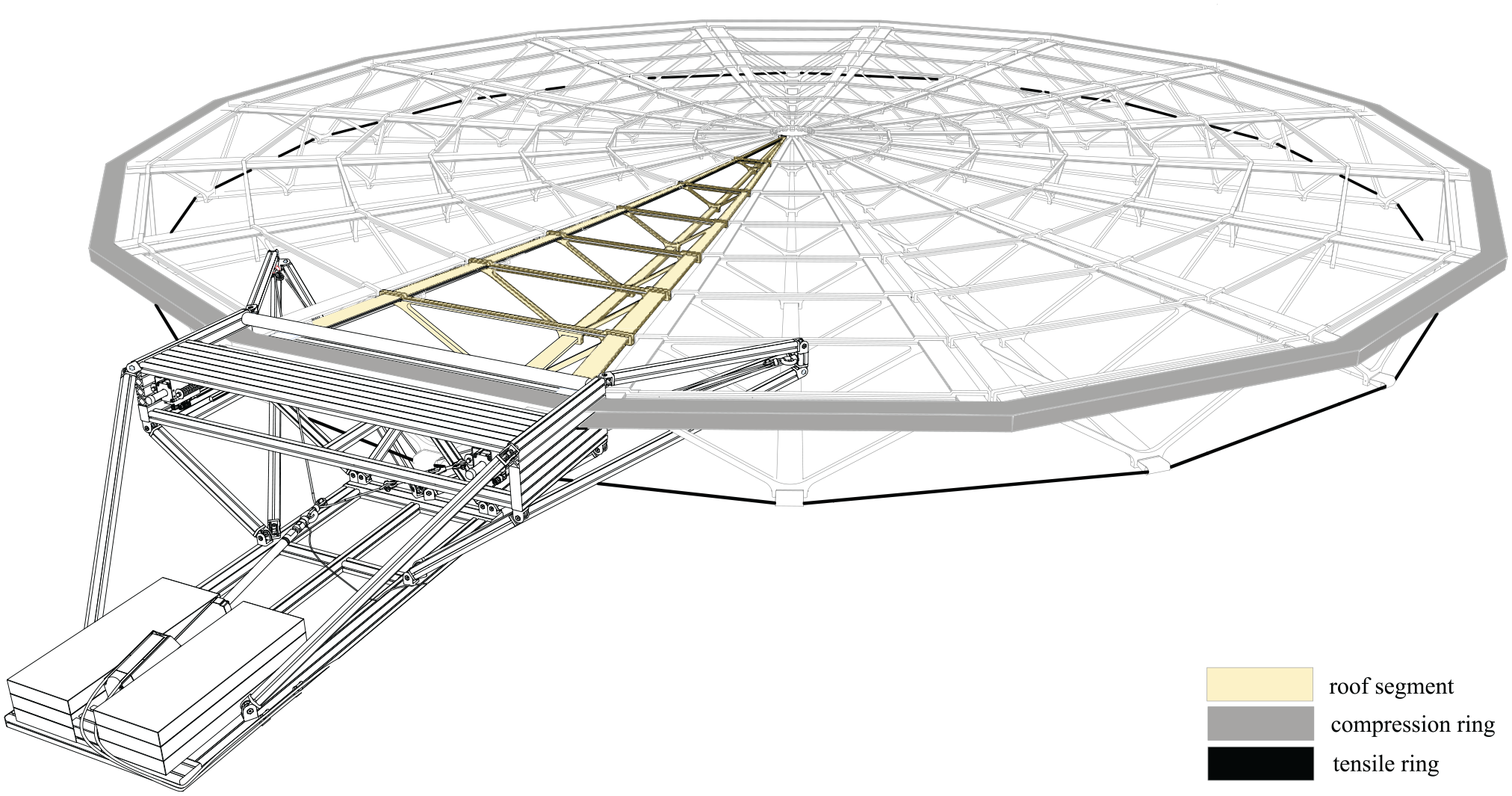
The structural concept, on which the prototype is based, imagines a circular balanced roof structure, consisting of multiple elastic kinetic segments (conceptual sketch in Figure 2 and rendering in Figure 3). These lightweight segments are inspired by the Fin Ray® structure. The tail fin of bone-fish is composed of v-shaped bones with connective tissue in between. If a load is applied on one of the bones, the tail deforms toward the applied load, which is unexpected and is termed the Fin Ray® Effect. This behavior allows fish to move very efficiently. 45
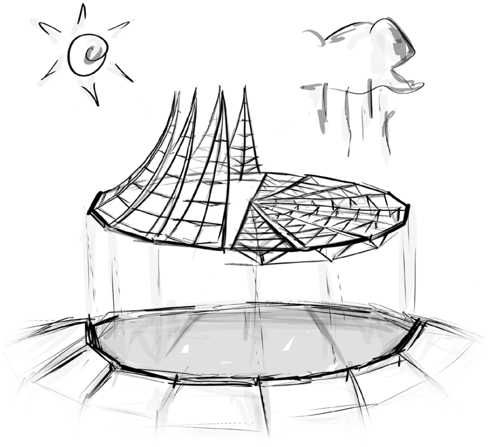
Conceptual sketch of a circular balanced roof structure. The partly opening is shown for demonstration purposes only, but not realized with the structural concept.
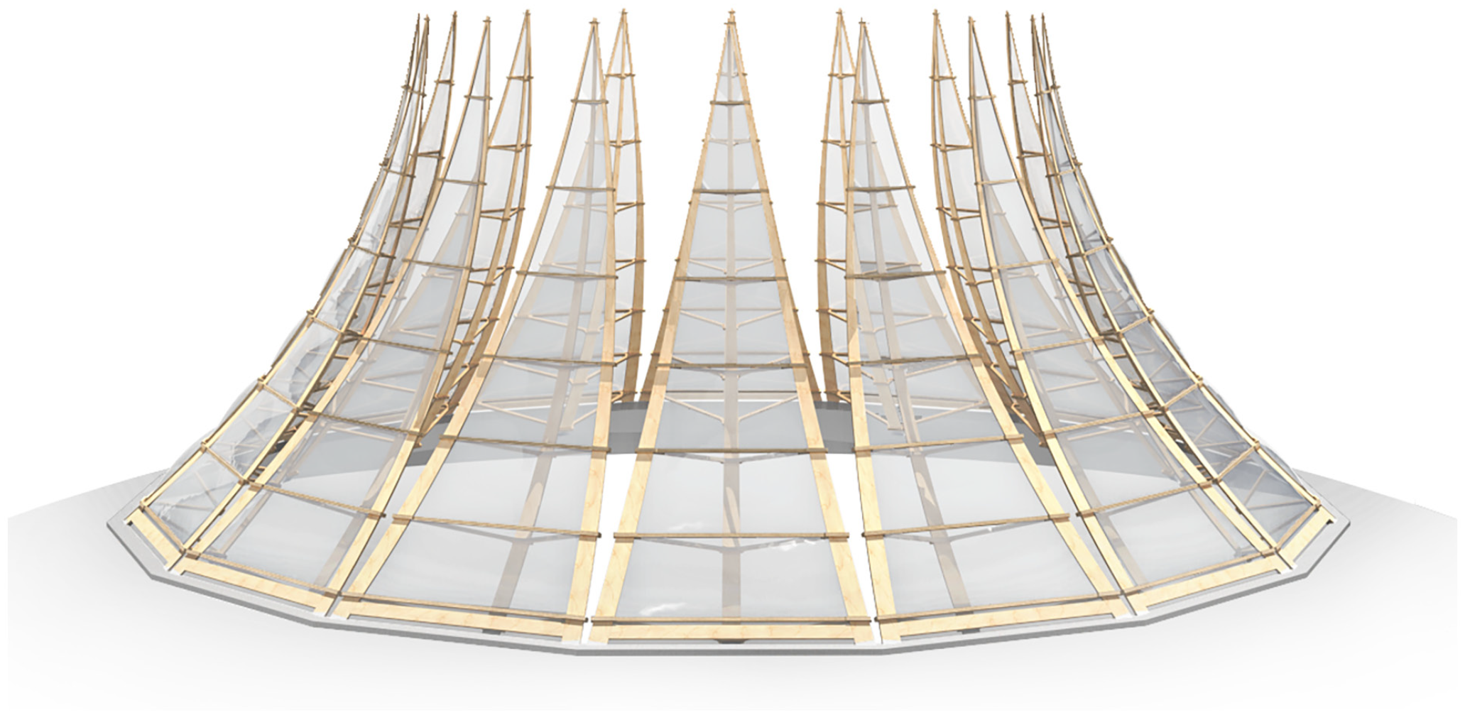
Rendering of the active hybrid roof structure concept.
Basically, one elastic kinetic segment can be interpreted as a three dimensional extension of the two dimensional Fin Ray® structure. The static system of the segment is shown in Figure 4. It consists of two upper and one lower flank. The flanks are coupled via pin-jointed braces. A special property of this structure is, that a small movement of the support is amplified to generate a large displacement at the tip. This makes the Fin Ray® structure an interesting candidate to design transformable structures.
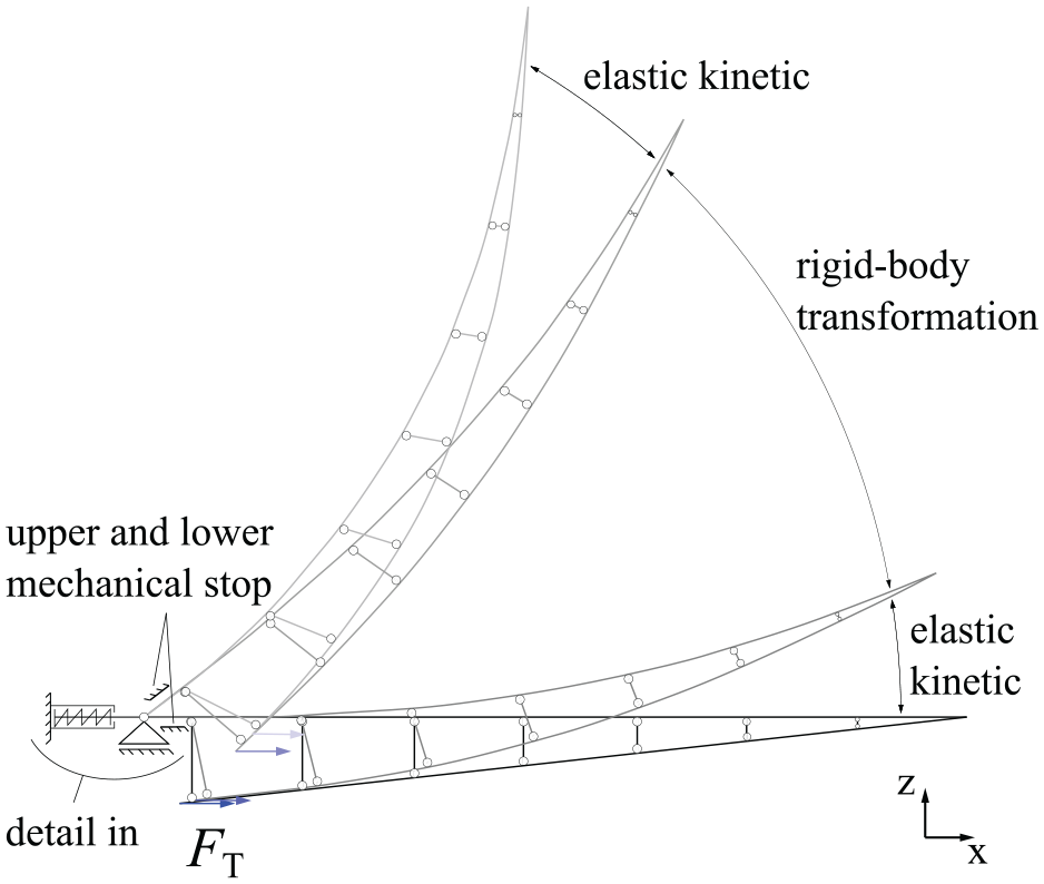
Static system of one elastic kinetic segment in side view. The transformation force
Bögle et al. 23 investigated the Fin Ray® structure for application in civil engineering in the course of a parametric study. With regard to the proportions of the static system, a height to length ratio of 1:10 was found to be a good compromise between load-bearing capacity and achievable transformation. 46
Investigations conducted at our Chair showed that the Fin Ray® structure allows a very energy-efficient transformation when actuated at the supports. 12
Transformation concept
The individual segments are radially arranged, as shown in Figures 2 and 3. Their reaction forces are balanced by a ring system, whereby the upper flanks are connected to a compression ring and the lower flanks are connected to a tension ring.
Balancing the system implies a coupling of the individual segments. This coupling is exploited in the transformation concept. By a reduction of the tension ring diameter, compression forces are introduced into the lower flanks of all segments. Consequently, a simultaneous transformation of all segments can be generated. For one segment, this is illustrated in Figure 4, where the transformation force
As the achievable elastic kinetic transformation is generally limited, we decided to use a combination of elastic and rigid-body transformation. This requires suitable support conditions at the upper flanks. For this purpose, the upper flanks are supported by a jointed connection, supplemented with two mechanical stops (see Figure 4 and detail of the upper support in Figure 5). With this support situation the overall transformation of one segment proceeds as illustrated in Figures 4 and 5: Starting in the closed state, the upper flanks are in contact with the lower mechanical stop. A pair of vertical forces
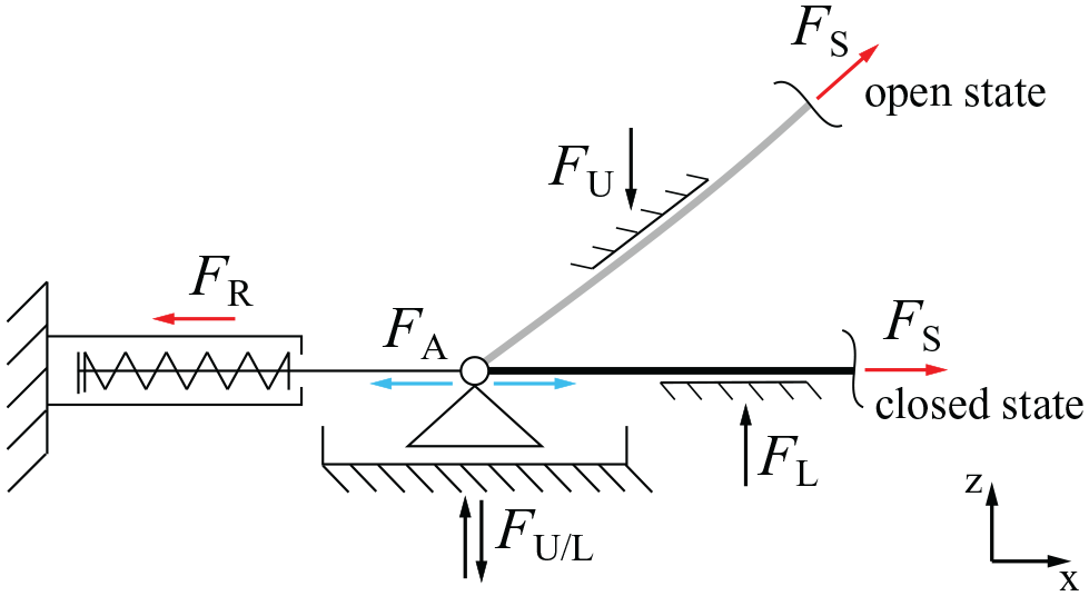
Actuated upper support of flank, horizontally movable and held by a compression spring. An actuator is attached in parallel and generates the adaptation force
Static and dynamic adaptation concept
Static and dynamic adaptation is realized by actuators, which have to be integrated into the structure appropriately. Looking at the prototype concept, two approaches are possible, on the one hand, the integration of actuators into the structure itself and, on the other, the integration of actuators at the supports.
Based on previous investigations regarding energy efficient actuator placement for a similar structure,8,12 we decided to realize a concept with actuation of the upper supports. This allows the actuators to be hidden inside the compression ring and the structure itself is kept simple and pure.
The concept of the actuated upper supports is shown in Figure 5. The support is movable in the horizontal direction. The horizontal reaction force
Load transfer
The load transfer for one segment in the open and the closed state under dead load is shown in Figure 6. In both states the loads from dead weight are transferred by tensile forces in the upper flanks and a compression force in the lower flank. During the transformation an additional compression force is introduced into the lower flank, which leads to an increase of tensile forces in the upper flanks. Consequently, the forces are generally higher in the open state, when compared to the closed state. Additional symmetrical loads result in an increase of tensile and compression forces in upper and lower flank, respectively. The forces in the pin-jointed braces, which couple upper flanks and lower flank, are tensile or compression normal forces, depending on the specific transformation state. In the closed state the braces near the supports tend to be under compression, whereas coming closer to the tip, they tend to be under tension. In the open state, most of the braces are under tension.
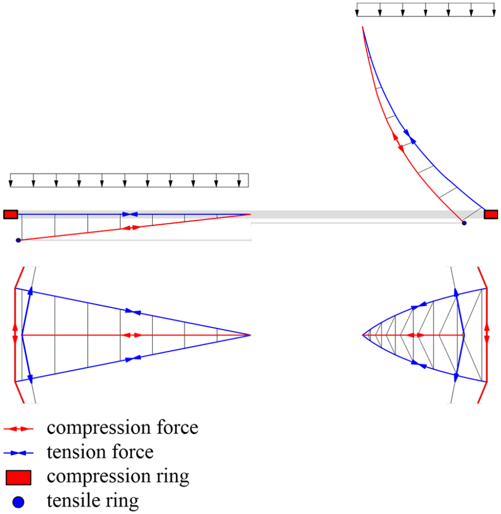
Load transfer under dead weight in closed (left) and open state (right) for one segment.
The circular arrangement of the individual segments, according to the structural concept, results in a radial formation of tensile forces from the upper flanks and compression forces from the lower flanks. Consequently, the radial tensile forces are transferred to the compression ring and the radial compression forces are transferred to the tension ring.
Prototype design
In the following, the design of one single elastic kinetic segment from the overall structural concept is derived and described in detail (Figure 7). The forces released from the balanced system are transferred via an aluminum space framework, which is described subsequently.
Prototype representing one segment of the active hybrid roof structure.
Elastic kinetic segment
The elastic kinetic segment is a timber structure based on a modular plug system. The size of the prototype is significantly influenced by the 3.90 m height of the laboratory at BTU.
The upper flanks with a length of 3.82 m are connected to an aluminum box girder representing a part of the compression ring (Figure 8). The lower flank with a length of 3.65 m ends in a 3D printed detail through which the cable of the tension ring is passed. Force flow-oriented, the cross-sections of the flanks taper from 10 cm width at the supports to 2 cm width at the tip. The thickness is constant at 12.5 mm. In total, eight braces are placed on the flanks at an uniform distance of 0.5 m (Figure 8). An important aspect was not to weaken the flanks cross-sections by the connections with the braces, since they undergo large elastic deformations. The birch plywood braces have a triangular shape and are manufactured from on piece using a CNC milling machine. This leads to reduced effort required for the production of connection details. Moreover, they allow a modular assembly. The braces, which enclose the flanks, are held in place using metal pins, one per upper flank and two for the lower flank. The largest brace has a height of 40 cm, a width of 130 cm, and a thickness of 21 mm. The dimensions of the other braces decrease toward the tip. The total timber dead load is only 11.6 kg. Together with the multi-chamber foil cushion and the mounted sensors, it increases to 14.75 kg.
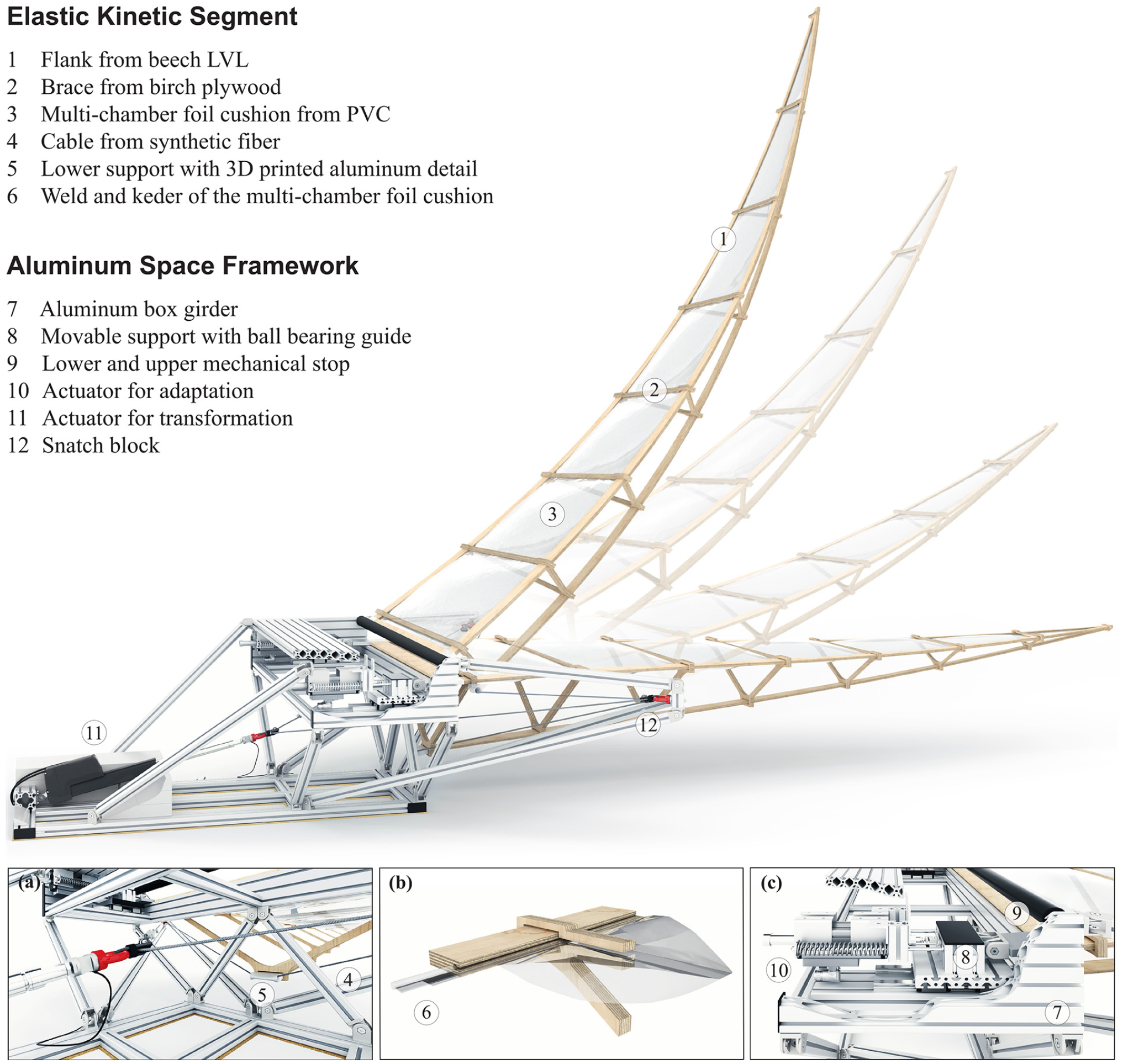
Transformation states of the prototype and its components: (a) connection of linear actuator and fiber cable, (b) connection of the multi-chamber foil cushion to the timber flank, and (c) movable upper supports with linear motors for adaptation.
The multi-chamber foil cushion serves as the roof closure. It is installed between the two upper flanks. One requirement of the roof skin is to ensure sufficient stiffness on the one hand and not to impair the transformation of the segment on the other. In addition to the very good lightweight properties, this variant offers sufficient stiffness as a secondary structure, because it is mounted between the flanks and passes through the upper gaps of all braces to the tip. At the tip it is fixed, so that loads can be transmitted efficiently to the surrounding timber structure. The edge of the cushion is fixed by an elastic keder, which is held directly in a timber notch of the elastically deformable flank, as illustrated in detail (b) in Figure 8. Since the prototype will only be used indoors, a PVC foil with a thickness of 0.5 mm is used instead of a weather-resistant foil.
Aluminum space framework
In the realized prototype, the aluminum space framework is the fixed part. This framework is only necessary for the prototype when one segment is detached out of the balanced tension and compression ring support system. The section of the compression ring is realized as an aluminum box girder. The box girder (detail (c) in Figure 8) includes two actuators, four spiral springs, two horizontally movable supports as well as a contact roll, enabling the control of the two upper flanks of the timber structure. In order to balance the tension ring force for the one segment prototype, the cable had to be redirected laterally. For this purpose, the two tripods are constructed, which are also composed of aluminum members. Two snatch blocks are attached to the tips of these lateral cantilevers so that the cable, which passes through the 3D printed aluminum detail at the wide end of the lower flank, can be guided to the back. These snatch blocks bearing a working load of 12 kN. The fiber cable, with a diameter of 6 mm, is then connected via a third snatch block to a linear actuator responsible for the transformation of the convertible part (detail (a) in Figure 8). The horizontal force resulting from the transformation process at the support of the linear actuator is balanced with forces of a member of each tripod, which meet in the front on the symmetry axis of the fixed part. In order to stabilize the whole free cantilever aluminum structure without additional anchoring, it is weighted down with concrete counterweights in the rear part.
Actuators and sensors
The linear actuator with a ball-screw drive sits in the back of the space framework (Figure 8). It has a stroke length of 300 mm, can generate forces up to 6.8 kN, and has a maximum velocity of 18 mm/s without and 14 mm/s under full load, respectively. An opening of the structure is realized by retraction of the linear actuator’s cylinder. The snatch blocks, attached at the cantilever tips, rotate with the changing cable angle during the transformation, guaranteeing safe guidance of the cable over the whole transformation space as well as in case of disturbance-induced vibrations. The actuator stroke is measured with an integrated position sensor. For a full transformation between open and closed state, the linear actuator’s cylinder is retracted by 250 mm, which takes approximately 15 s. Moreover, the force, which is generated by the linear actuator, is measured via a force sensor attached between the cable and the linear actuator’s cylinder (detail (a) in Figure 8).
For adaptation, the two upper supports are designed to be movable (detail (c) in Figure 8). Thereby the movable support is realized as a recirculating ball bearing guide. This guide has static friction of approx. 10–20 N and can carry high loads in the vertical direction as well as moments, around the flank and the global vertical axis. The supports are connected to a linear motor each. The linear motor is a direct drive actuator with permanent magnets. This type of actuator is very compact and highly dynamic. It can generate peak forces of up to 325 N with a maximum acceleration of more than 200 m/s 2 and a maximum velocity of nearly 6 m/s. With these properties, it is well suited for dynamic investigations and dynamic adaptation purposes. The continuous stall force with passive cooling is 50 N. This force can be continuously generated by the linear motor without overheating and may later be used for static adaptation purposes. In order to carry the static support load and hold the structure in equilibrium, without the need for a permanent actuation, two compression springs on both sides are used, with a spring stiffness of 9 N/mm each. This horizontal degree of freedom of the upper supports leads to a support movement of approximately 30 mm during the transformation, due to an increase of normal tensile forces in the upper flanks.
The linear motors can be activated only when needed and generate additional forces onto the movable supports. A force sensor is attached between the actuator’s slider and the movable support on each side to measure the generated forces. This way, the current-controlled motors can be supplemented by a force feedback loop, that enables force control. Moreover, the actuators include a position sensor, which allows position measurement of the upper supports and is used for position control. The actuators can be driven in a synchronized way as well as independently to counteract both, vertical bending modes and torsional modes.
Structural responses are measured via three 9 degrees of freedom inertial measurement units (9-DOF IMUs). These sensors deliver accelerations, angular rates and magnetic field data in local space. Combining this data (using e.g. Kalman Filter) dynamic roll and pitch angles can be derived. Statically these angles can be used to determine the structure’s current transformation state.
Modeling and dimensioning
Using the software SOFiSTiK, separate models are generated for the two parts that constitute the prototype, one for the timber structure (Figure 9) and the other for the fixed part. As the prototype is located in the laboratory, only dead loads are considered. The form finding in the closed state is performed with the intention of achieving straight upper flanks under dead load (Figure 9 bottom). For this purpose, in the form finding process the structure is arranged in a cambered configuration (Figure 10 top) and iteratively adapted with respect to the magnitude of the camber. Additionally, a form finding is performed regarding the air pressure and the related geometry of the foil cushion. The result of the real form finding can be seen in Figure 10.
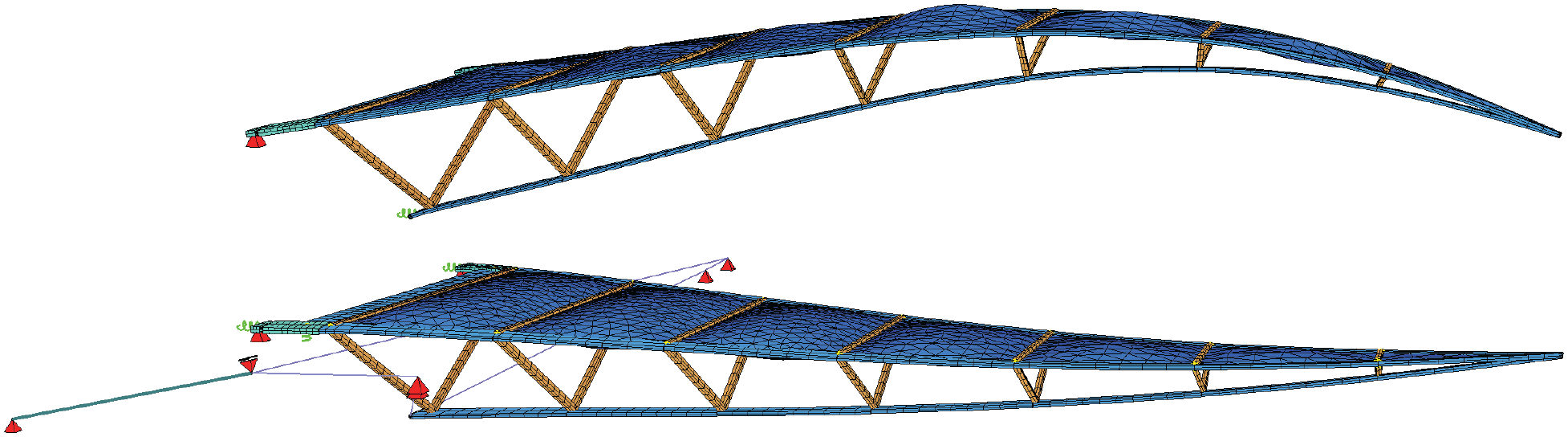
Finite element model in the cambered state (top) and in the form found state under dead load (bottom).
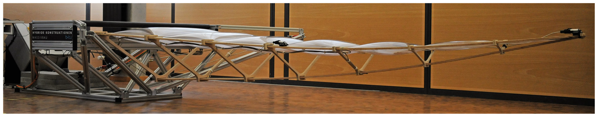
Form found active hybrid roof structure prototype at the Chair of Hybrid Structures – Structural Concrete at the BTU Cottbus-Senftenberg.
First of all, the FEM analyses are performed for the convertible part, where a Young’s modulus
The three tapered flanks and the braces of the timber structure are modeled using beam elements (Figure 9). They are connected by hinge couplings acting around the weak axis of the flank cross-sections. For modeling, a couple of assumptions and simplifications are introduced. Firstly, the tapered cross sections of the prototype’s flanks are approximated by simplified step-wise constant cross sections. Secondly, the braces are connected in the middle of the flanks, whereas in reality the braces enclose the flanks. To account for an increased torsional stiffness of the prototype, based on simulation results, the shear modulus is increased by 15% compared to the one given by the technical assessment. 38 In addition, the friction behavior of the 21 hinged connections between flanks and braces is approximated by the introduction of equally chosen rotational springs at the upper connections of flanks and braces. However, the actual hinge effect of the individual flank – brace connections highly differs, depending on the manufacturing tolerances.
The multi-chamber foil cushion, modeled with quad elements, is fixed to the inner sides of the two upper flanks. Thus, the forces from the form found cushion, which are generated by applying an internal pressure of 0.04 kN/m2, are transferred to the timber structure.
The changing support conditions during the transformation at the two upper flank ends represent a significant aspect of the modeling. The mechanical behavior of the spiral springs and the mechanical stops is modeled using spring elements. Thereby, the spiral springs are linear springs with a spring constant of 18.04 N/mm, which corresponds to the springs actually used in the prototype. The springs representing the mechanical stops inhabit a large spring constant of
For the bearing of the cables, a support is modeled at each of the two symmetrically arranged points at which the snatch blocks are located. The support allows the cable to slide through. At the bottom rear end, a support is modeled to which the cable is finally fixed. The actuator which causes the transformation is modeled by a shortening of the cable. In this way, it is possible to analyze the complete transformation behavior of the timber structure with the multi-chamber foil cushion.
In order to realize the straight geometry of the timber structure the camber of the timber structure is determined iteratively. The large bending elastic deformations resulting of the camber can be modeled with a command (ACTB) that analyzes the initial bending stresses of curved geometries assuming that they were originally straight. The transformation process is analyzed by means of a load capacity iteration, which includes the use of primary load cases. In this way, the relevant load cases for the design can be observed.
The decisive states for the dimensioning are the open transformed (Figure 11(c) and (d)) and the cambered state (Figure 11(a)) of the timber structure. The maximum bending moments (cambered: −26 Nm; form found: −38 Nm; fully transformed: 56 Nm) occur in the flanks. The maximum normal force of −601 N in the flanks is located at the rear end of the lower flank in the fully transformed state. The maximum bending stresses of 29 N/mm2 and maximum shear stresses of 0.3 N/mm2 occur in the fully transformed state at the widest point of the flank cross-section. Within the braces, the first brace (i.e. the largest brace) is the one with the highest exposure by a normal force of 607 N. In this open configuration the force in the cable is 2.2 kN.
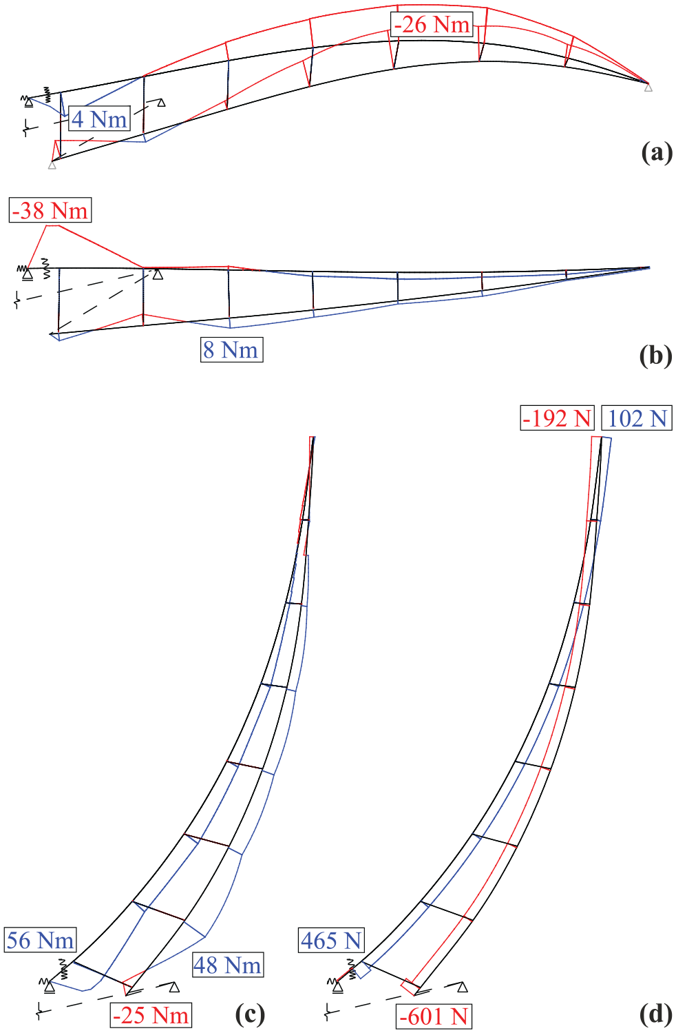
System cutout with Normal forces [N] and bending moments [Nm] for different load cases: (a) cambered state with temporary support at tip and lower flank, (b) form found state, (c and d) fully transformed state (only one upper flank is shown).
The geometry of the fixed part (Figure 8) is generated by a specific optimization, considering the positions of the flank ends, the position of the compression ring and its installation space as well as the positions of the snatch blocks and the counterweights. Based on these boundary conditions, a parametric model of a spatial framework is created on which the reaction forces of the convertible part are applied as loads in the form of single forces. All bracing members of the fixed part are variably modeled with respect to their positions using five parameters. The variable geometry of the parametric model is dependent on horizontally axis symmetric conditions with respect to their nodal coordinates. For the optimization of this variable FE-model, a self-implemented optimization algorithm based on an axis parallel cross search is employed. It first sorts the entries of the vector of design parameters of the given parametric model according to their determined influence on the objective. Subsequently, a hierarchical optimization is employed. In the design process of the fixed part, this procedure is performed several times for different ratios of the criterion mass to deformation in order to validate the algorithm and determine a pareto-optimal solution of the structure that, in addition to optimal values in terms of minimum mass and minimum deformation, also has the visual appeal of a suspended light structural effect. Also for validation purposes, all the results are validated with the results of the complete solution space with 129,600 possibilities and a multi-criteria optimization using a surrogate model. For this optimization procedure the target criteria of stiffness and mass are chosen and the entire pareto-front is determined. Thus it can be ensured that the result of the implemented algorithm is pareto-optimal. For the investigated parametric model the application of the algorithm can save a significant amount of time compared to the calculation of the entire solution space and also compared to the optimization using a surrogate model the axis parallel cross search can find the solutions more efficiently. However, more complex models could cause problems for this hierarchical algorithm with respect to local extreme values. After the performed analysis and validations the obtained solution is used as a basis for a more detailed modeling in SOFiSTiK. Besides the loads from the convertible structure, this model also allows an analysis regarding the counterweights necessary to stabilize the structure.
Construction
After the modeling and dimensioning, the fabrication and assembly of the structure is performed, illustrated in Figure 12. At the beginning the braces are positioned at one of the upper flanks (Figure 12(a)). Then the multi-chamber foil cushion is placed (Figure 12(b)). Afterward the remaining flanks and the closing timber member for the multi-chamber foil cushion are attached (Figures 12(c) and 13). Thereafter the timber structure is mounted to the fixed part and the braces are positioned and bolted to the flanks equivalent to the predetermined cambered position (Figure 12(d)). Finally, the multi-chamber foil cushion, which is integrated in the form found timber structure, is filled with air until the previously determined air pressure and the corresponding cushion thicknesses are reached (Figure 12(e)).
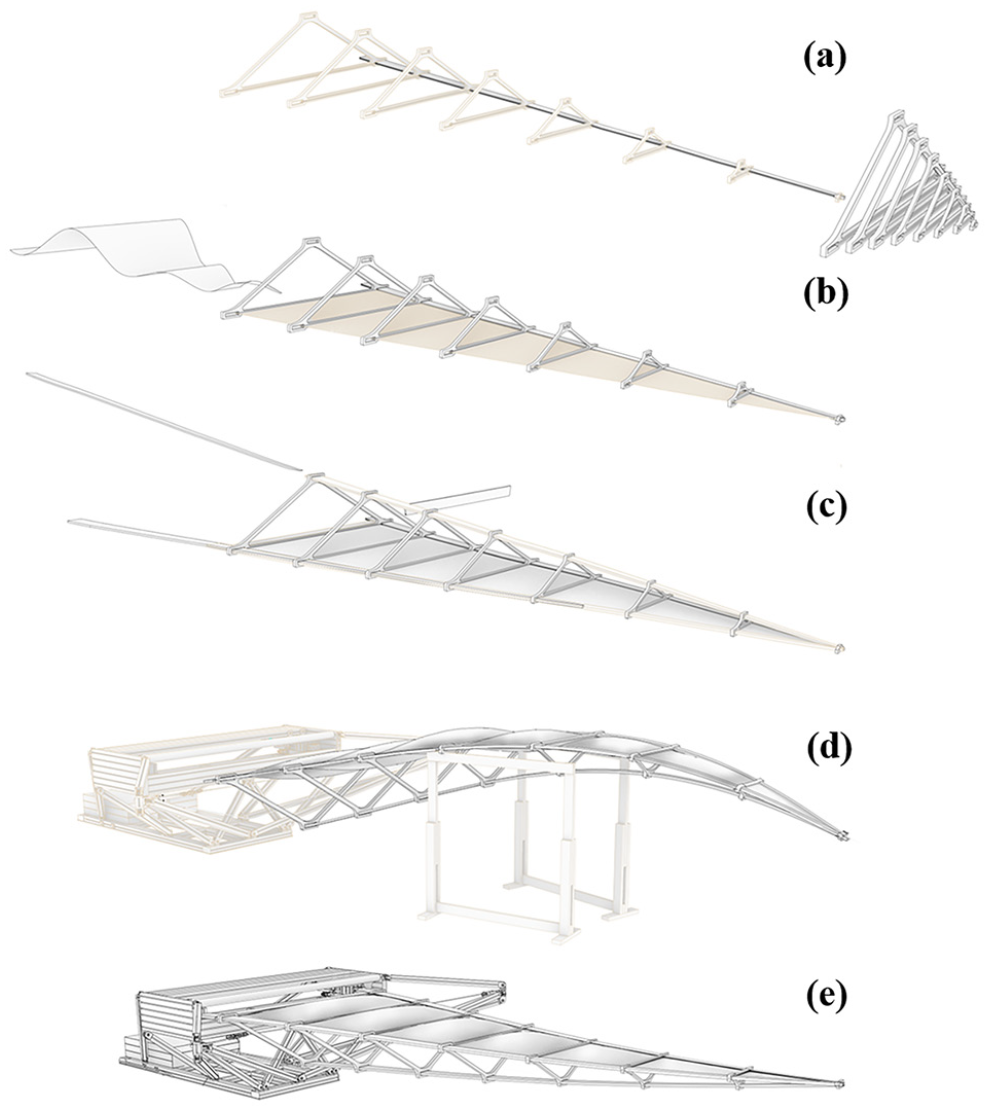
Assembly procedure of the prototype in steps: (a) positioning of braces at one of the upper flanks, (b) insertion of multi-chamber foil cushion, (c) insertion of remaining two flanks and of the closing timber member, (d) bolting of braces in predetermined cambered configuration and (e) inflation of multi-chamber foil cushion.
Insertion of the lower flank as part of assembly step (c).
Experimental validation
Within the scope of the experimental investigations, both static and dynamic experiments are carried out, with the aim to identify the static and dynamic structural behavior over the transformation space and to validate the above derived finite element model.
The actuation and measurement concept used for the experimental investigations is depicted in Figure 14.
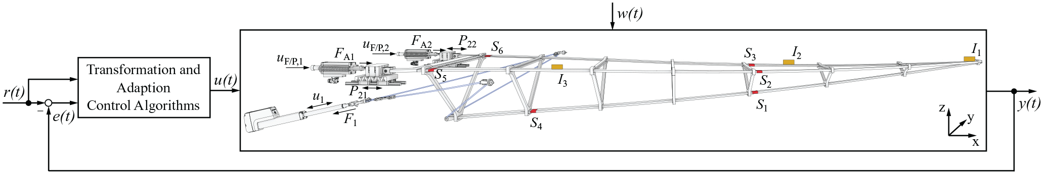
Measurement, control, actuation, and transformation concept of the prototype, with reference variables for transformation and adaptation
Within this concept, the actuation variable
Structural responses due to static and dynamic loads
The transformation force, applied by the linear actuator is given by
Strain gauges are placed at locations
The dynamic responses are measured via the three 9-DOF IMUs
Static analysis
In order to analyze the structural behavior over the transformation, a total of six measurements are conducted. The transformation is given in terms of the linear actuators cylinder retraction
The experimental and simulation results for support forces and pitch angles are given in Figure 15, the bending stresses are presented in Figure 16. Since all the six measurements give similar results, only the result of one measurement is presented. Moreover, note that the initial bending stresses resulting from the cambered state are not included in the comparison, as they cannot be measured with the strain gauges.
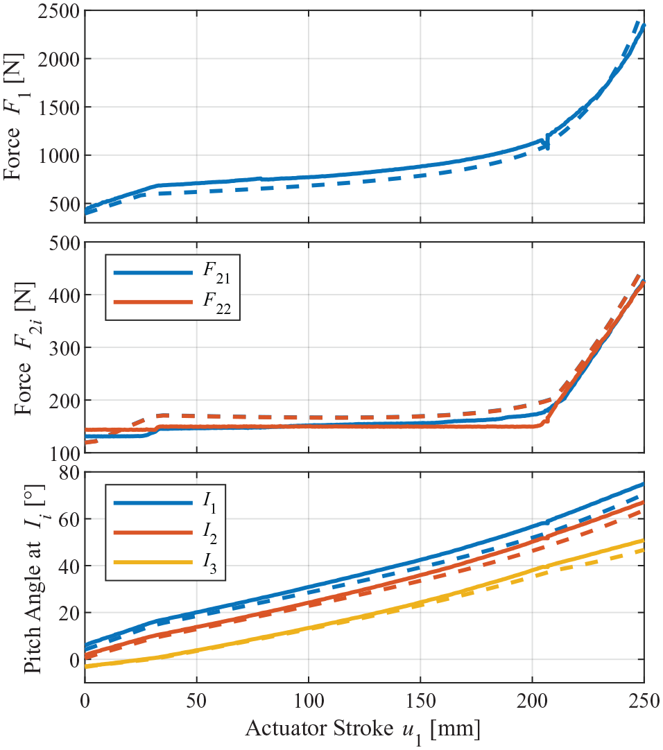
Transformation force
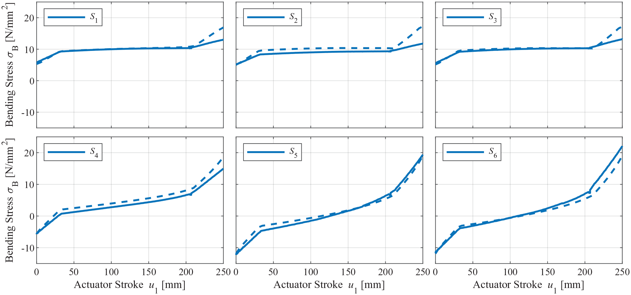
Bending stresses at strain gauges
The combination of elastic kinetic and rigid-body transformation is realized by the change of supporting conditions between fixed and pin-jointed. Until approx. 30 mm and from approx. 210 mm cylinder retraction, the transformation is elastic kinetic (i.e. supporting condition is fixed), whereas within these borders it is rigid-body (i.e. supporting condition is pin-jointed). The change of supporting conditions at these actuator strokes (30 and 210 mm) can be observed in most of the resulting data curves in the form of points of discontinuity.
The measured transformation force
The horizontal reaction forces (Figure 15) of the movable upper supports show clear deviations at the beginning of the transformation. Whereas the simulated forces linearly increase, the measured forces stay constant, which is due to static friction between the flanks and the lower mechanical stop as well as static friction of the upper ball bearing guides. These friction effects are not included in the simulation. However, they have a significant influence on the results, especially for small measurement values. In the course of the transformation the deviations start to decrease, as forces increase and the flanks lift off from the lower mechanical stop. The different behavior of the two movable supports is due to a higher static friction of the second support’s ball bearing guide, which was observed during the experiments.
The deflection shape over the transformation is compared by means of the IMU pitch angles (Figure 15). At the beginning of the transformation, the three pitch angles show a good agreement with the simulation result. During the transformation, the deviations are becoming more evident, particularly for IMU
The calculated bending stresses (Figure 16) show a good agreement for the six locations
Both the analysis of the IMU pitch angles and of the bending stresses indicate differences in the curvature behavior toward the tip of prototype and model. At this point it should be kept in mind that a couple of simplifications were introduced for modeling, which may influence the curvature behavior.
Modal analysis
An experimental modal analysis is carried out, in order to reveal the prototype’s dynamic behavior over the transformation.
Firstly, impulse responses are conducted for 10 different transformation states, equally distributed for rigid-body and elastic transformation. The inputs are applied open-loop at the upper supports by means of motor current. The motor current impulses of 3 A are held for 0.01 s, generating forces
Subsequently, the amplitude spectra of accelerations and angular rates, given by IMUs
Finally, the natural frequencies are determined based on the measured free responses. This is done as before, by calculating the amplitude spectra of local z-accelerations, and x- and y-angular rates, followed by a peak detection.
The experimentally identified natural frequencies over the transformation are depicted in Figure 17 together with the modal analysis results of the finite element model (dashed lines). To show the effect of increased static friction for the elastic kinetic transformation sections, modal analysis results with fixed upper supports are also provided (solid lines). These fixed supports represent static friction, which is not overcome during experiments. Moreover, in Figure 18, the determined four mode shapes are shown for the finite element model in the closed and the open state.
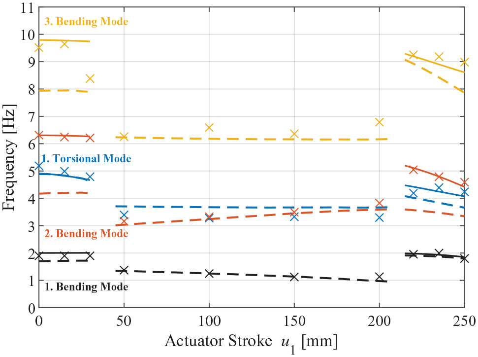
Natural frequencies of the first four mode shapes over the transformation for simulation (– –) and experiment (
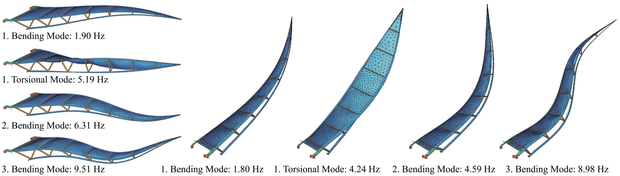
First four mode shapes with natural frequencies determined in the experiments for the closed state and open state.
Looking at the natural frequencies of simulation and experiment, the sections of elastic kinetic and rigid-body transformation can be clearly distinguished (Figure 17). For the elastic kinetic sections, the natural frequencies are generally higher than for the rigid-body transformation section in the middle. This effect is expected, as a fixed support condition increases stiffness compared to a pin-jointed support condition.
Comparing the natural frequencies of simulation and experiment for the rigid-body section, a good agreement can be stated, especially for the bending modes. For the first torsional mode, simulation results are slightly larger than the experimental results.
For the elastic kinetic transformation sections, the simulation results (dashed lines) show significant deviations from the experimental results, depending on the considered mode. They are clearly visible for the second and third bending mode. These deviations can be explained by increased friction. For the first elastic kinetic section, there is increased friction due to the contact between the flanks and the lower mechanical stop. For the second elastic kinetic section, friction results from a significant increase of the vertical forces acting on the movable supports.
In order to verify this explanation, we conducted a modal analysis with the finite element model, where the upper supports were fixed (solid lines). These fixed supports represent static friction, which may not be overcome during experiments. The results obtained this way show a good agreement with experimental results, especially for the second and third bending mode. For the first bending mode and the first torsional mode, the effect of fixed supports is not that significant.
The experimental results, which were presented in Bleicher et al. 13 for the first bending and the first torsional mode, confirm these results. However, they differ from the ones presented here in the way of excitation. Therein the structure was deflected by hand into the corresponding mode shape and the free vibration response was captured.
Conclusion and discussion
In the framework of this contribution, the concept and design, modeling and dimensioning, and the construction of an active hybrid roof structure prototype are presented. This concept is characterized by a stable transformation, that is shape adaptation based on elastic kinetic and rigid-body motion. The lightweight timber design is sustainable, beneficial for resource efficiency and allows energy-efficient actuation. Nevertheless, the lightweight design makes the structure prone to external disturbances. For this reason the concept includes the idea of static and dynamic adaptation, which has been proven to improve load-bearing and serviceability with the same or less material usage. In the future, the concept can be further developed for larger spans.
Furthermore, this contribution presents the experimental evaluation of a realized prototype by means of static and modal analyses.
The results of the static analysis indicate, that the developed finite element model can be used to estimate stress states over the whole transformation range. However, so far the static analysis was conducted for dead load only. In future experimental investigations, the structural behavior under additional symmetrical and unsymmetrical load situations has to be evaluated and compared to finite element model results. In a next step, static load adaptation algorithms can be investigated.
The results of the experimental modal analysis are in accordance with those of the developed finite element model. They reveal natural frequencies well inside the region of external disturbances (e.g. wind). Furthermore, the natural frequencies are changing during structural deployment, there are even frequency jumps due to the change of the upper support conditions. In next steps, we will investigate the model-based control design for a realization of dynamic adaptation, which will be a challenging task considering this dynamic behavior.
Footnotes
Declaration of conflicting interests
The author(s) declared no potential conflicts of interest with respect to the research, authorship, and/or publication of this article.
Funding
The author(s) received no financial support for the research, authorship, and/or publication of this article.