
Abstract
This paper presents the use of a computational design algorithm in combination with robotic fabrication and sensing to augment the design and construction process for non-standardized material. Although reusing reclaimed material can significantly reduce the environmental impact in building construction, current design processes are not set up for this shift in thinking. Contrary to conventional practices, designing within the constraints of available material means that geometry and topology cannot be fully pre-determined. This paper introduces a design methodology for corrugated shell structures from folded sheet metal of variable geometries and properties, in which the design goal adapts to available material. It follows a two-fold approach of digital algorithm development and scanning and physical prototyping for robotic fabrication. The scanned materials database is classified based on object geometry data and material properties; such as thickness, type of metal, and spring-back values for fabrication purposes. Together with a target surface, it is an input for a generative design algorithm consisting of surface generation and optimization. The surface generation tries to approximate the target through a translation of search algorithm results for object placement into a 2D mesh graph which is then linked to 3D particle spring based form-finding. The optimization consists of evaluation of structural, fabrication, and design criteria, with finally user selection. Robotic fabrication included object recognition, metal sheet folding and consideration of different metal spring back behavior. These methods were tested on a single curved arch surface and applied to a double curved cantilever canopy as a final demonstrator. The algorithm results showed a generation of different corrugated shell topologies based on iterated object placement. As a demonstrator, a part of the selected canopy was robotically fabricated from local industrial leftovers.
Keywords
Introduction
This research presents the development of a generative design algorithm and a robotic fabrication workflow that leverages the capacity of digital technologies and data processing for a design approach with non-standardized material. This expands the existing design strategies in the field of re-use and designing with available material in the context of computational design and robotic fabrication.
The building sector is a major contributor to material consumption 1 energy usage and greenhouse gas emission 2 , and waste. 3 Most of the embodied environmental impacts of buildings are related to the linear processes of raw material extraction, production, construction, demolition and disposal without considering all stages of building material life and its reuse. While circular economy principles of “reduce-(repair)-reuse-recycle” 4 are becoming more and more applied due to the environmental crisis, the current approach to reduce the environmental impact of the construction industry is mainly focused on recycling. However, recycling involves energy usage for reprocessing of materials and may not always be the best solution for material with high embodied energy, such as metal or plastic. In contrast, reusing material has the potential to further reduce environmental impact because less energy is spent for reprocessing. 5 However, reuse comes with additional challenges which are due to the inherent irregularities in the left-over materials. Specifically, most of the construction and industry produced waste and leftovers are of irregular shapes and mixed materials due to current disassembly strategies 6 and manufacturing processes. 7 Thus, reuse requires unconventional strategies in design and fabrication to deal with non-standardized materials.
Designing with non-standardized material
Using non-standardized irregular material for construction, from “naturalized” raw wood 8 or bamboo 9 to stones found in Inca’s masonry 10 and even reusing building elements 11 such as in Roman spolia, 12 was common practice in vernacular architecture. On the other hand, contemporary architecture lies on the foundation of industrialization and standardization. 9 In conventional modern practices, raw materials, such as trees and stones, are highly processed before being used in construction. This allows treating them as an infinite set of identical elements, whereas using the pieces in their original form poses constraints and limitations in the design process. 13
Including reuse and reclaimed materials into architectural construction involves reversing the conventional design process. Designing within the constraints of available materials means that geometries cannot be fully predetermined, as they are constrained by “unknown” elements and properties. This means a change in design paradigm where element characteristics become inputs, and system geometry and topology the outputs of the design process.14,15 Such change in paradigm has become possible through novel computational design and digital fabrication technologies.
Previous research shows the use of novel processes such as genetic algorithms and optimization to decrease complexity and increase efficiency when designing with non-standardized material. In the work of SXL design of truss structures from reused structural steel elements was explored through stock-constrained optimization both through (a) object placement assignment and (b) a cutting stock approach where elements could also be partitioned into one or more pieces.16,17 The Elastic Gridshell Project on the other hand presents an approach where individual bending stiffnesses of discarded skis were measured and the values used in a bending simulation to determine the final shape of a gridshell. 18 One of the main obstacles to reuse of leftover material in design and construction in particular is the lack of a material database infrastructure. 5 A recent example of creating reclaimed material databases is the Rotor Deconstruction 19 cooperative. However this is possible only due to the standardized nature of the objects due to manual dismantling of building components.20,21 Further state of the art projects incorporate machine vision 22 with robotic fabrication into their workflows to extend the design space onto non-standardized materials. In Cyclopean Cannibalism each rubble stone is custom carved as ancient construction thinking from Incas is translated into procedural logics for object placement in a target geometry. One of the main aspects was sorting objects based on geometry and linking them to specific steps in linear digital assembly sequence. 23 The project Woodchip Barn by AA Design and Make creates a vierendeel arch structure from wood logs by iterating through different placement options in Galapagos and using robotic fabrication for custom joints.24,25 Creating customized joints is one of the most common approaches to account for unpredictability of natural material as can be also seen in the growing number of projects utilizing 3d printing such as the Sombra Verde project. 26 In “Natural Wood Log Structures with Stochastic Assembly and Deep Learning” evolutionary algorithm and network training include user ranking of placement options while exploring the potential of simultaneously designing and constructing with unknown material. 27 This project as well as a growing number of projects outside construction such as Dreamcatcher by Autodesk 28 and Delve, 29 showcase the potential to explore alternative solutions by enabling the designer to set a definition of a problem through goals and constraints rather than modeling a specific geometry (Figure 1).
Prototype.
Design based on availability: A generative design and robotic fabrication approach
The aim of this research is to develop a computational design and robotic fabrication workflow for designing with non-standardized material.
This paper introduces an integrated computational design to fabrication methodology for corrugated shell structures using leftover sheet metal. Corrugated shells gain structural depth through folding which makes them suitable for designing with flat material. In addition the different mechanical properties such as different stiffness and strength values of leftover sheet metal can be mitigated through folding. The scope of the project therefore covers robotic sheet metal folding and the development of a generative algorithm which takes user design goals and restrictions of the available material as an input to generate solutions within the given constraints.
This paper highlights the potential of combining new technologies of generative algorithms and robotic sensing in the design of non-standardized material. It calls into question the typical linearity and pre-determinacy of the design processes and suggests a codependency of the design solution to the limitations and unpredictability of reclaimed available material.
Methodology
The research methodology is structured into three main areas: (i) tectonic study, (ii) generative design algorithm development, forming the design methods, and (iii) physical prototyping and hardware development for robotic fabrication.
Within the tectonic study construction principles for corrugated shells were examined and translated into rules and procedures for implementation in the generative design algorithm, while within the algorithm development different strategies such as learning, form-finding and structural analysis were used. In robotic fabrication, strategies to combine sensing and material recognition were used in the development of a fabrication setup.
The following chapters will describe in detail the method development for each of the areas.
Design methods
Corrugated shell tectonics: System logic and placement procedures
Corrugated shells are folded surface-active structures in which bending stiffness is increased through the folding depth in the direction parallel to the corrugations. This chapter will present a tectonic study of these types of structures used to determine and translate its principles into object placement rules and procedures that were integrated into the computational design and digital fabrication workflow. The study considered strategies for object placement based on geometry and properties, as well as fabrication and connection logic for sheet metal. It is conducted through surface analysis in Rhino, empirical testing, and sheet metal prototyping.
The translation of procedural logics for object placement was examined on two scales: (1) global scale considering target surface requirements and (2) local scale considering implications of available material pieces.
Global scale: Design surface rules
The global scale study dealt with developing a surface approximation method. In its most basic form, a single curved surface with two linear supports consists of a series of arcs spanning between linear supports. The arcs can be considered as the main linear directions of the surface, and therefore the surface can be abstracted as a series of curves on the surface. The length and direction of these curves can therefore be considered as a guide for object placement (Figure 2(a)).
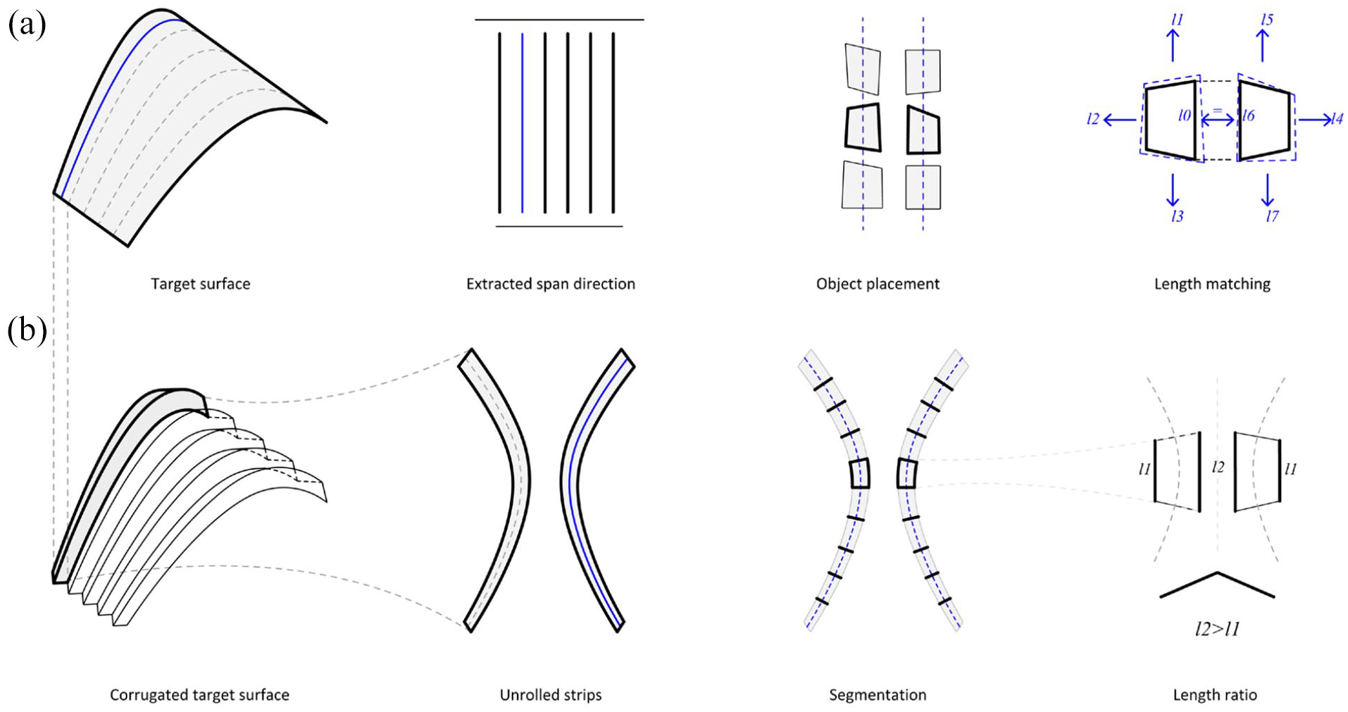
Global Scale tectonics rules study: Single curved surface abstraction: (a) object placement strategy, (b) surface approximation strategy.
When approximating a corrugated (initially) single curved surface we have to take into account that it is necessary to use flat planar pieces of material. Therefore in this study, the corrugated shell consists of only developable strips. Each corrugated arc can be considered as two disjointed developable strips with positive Gaussian curvature at the seams. Unrolled these strips follow curves of opposite directionalities. This is due to the height produced by the corrugation which establishes a longer and shorter edge rule. A basic segmentation of the two disjointed strips therefore suggests that the ideal subdivision consists of mirrored trapezoid pieces (Figure 2(b)).
Based on this several conclusions can be made for ideal object placement. The procedure for creating a “generic” corrugated surface considering only the geometry of the pieces is as follows. (1) Sort material into types—prefer trapezoidal pieces. (2) Set orientation of the object vertically. (3) Select pieces that are roughly the same size and proportion to each other. (4) Seek and select the best match that fits adjacent to the previously placed object based on edge length. (5) Check the best match so its’ edge length fits adjacently to the previously placed piece to the side. (6) Place best match. (7) Continue the process from steps 2 to 6 until reaching target surface length and width.
This same principle can be applied to interpret both synclastic and anticlastic surfaces and more complex geometries as long as the span direction and supports are defined. Important parameters to consider when designing with unknown material are (a) topology of the surface, (b) support conditions, and (c) support type.
Figure 3(a) shows the basic principle of different surface approximations with different topology and support condition combinations; (I) single-curved surface with two linear supports, (II) anticlastic surface with two curved linear supports, (III) synclastic surface with three linear supports, and (IV) anticlastic surface with a single linear support. Cases I–III demonstrate the impact of surface topology on choice of objects based on the overall target width and length, such as placing objects of equal width or objects of increasing width. While Case IV shows in particular how the support conditions determine the placement of objects based on material properties where heavier and/or stiffer material is placed at the bottom.

Global scale tectonic rules: Surface interpretation I–IV: (I) two linear supports condition/single curved arc surface, (II) two linear supports/anticlastic surface, (III) Three linear supports / trimmed synclastic surface, and (IV) single linear support. (a) Surface (b) abstraction (c) strip width, and (d) object placement based on object width and (e) based on object material properties.
Local scale: Object availability rules
The local rules study dealt with developing a bottom-up approach for object placement based on unpredictability of available stock material. While the global study showed that the ideal pieces for creating a “typical” corrugated surface are trapezoids of similar size and proportion and that the target surface determines object placement based on material type, in the case of surface approximation based on limited available material it is highly unlikely ideal conditions can be met.
There are several things to consider when dealing with unknown material; (a) different thicknesses of sheet metal, as well as different material properties, require different degrees of folding to achieve the same required surface stiffness, and (b) variations in object geometry have implications on global surface division. Consequently, this study had two main objectives at the scale of the object. (1) To set up a hierarchy of rules for “best match” piece selection. And (2) to describe implications of any selected match on the overall global surface corrugation.
For both of these, the starting point was listing the range of possible object geometries and material property variations that the corrugated shell tectonic could work with. Geometrically these are: (I) trapezoid, (II) rectangular or quad objects, and (III) triangular pieces.
The hierarchy for object type selection based on (1) material waste and (2) corrugation complexity. Geometrically this means “IF there is no ‘best’ match (trapezoid)—THEN select the next possible ‘best’ match”(quad else triangle). Materially this means prioritizing selection of objects of the same properties and stiffness to maintain an equal level of corrugation, followed by pieces with similar performance.
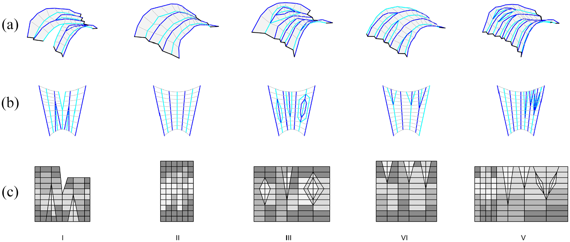
Figure 4 illustrates how selection (or availability) of different objects affects the global surface corrugation in four cases. Each object placement choice is the basis of building up a single corrugated arc. Case I shows “ideal” object selection where objects of same geometries and proportions are available, therefore producing a consistent corrugation. Cases II, III, and IV, on the other hand show a change in corrugation that is necessary when objects of different (II) properties, (III) large size variations or (IV) different geometry families need to be connected. Therefore “branching” is introduced in the corrugation. This enables a transition from a single corrugation (of a set width) to multiple corrugations (adding up to the same width) and can mitigate different material stiffness requirements or reduce offcut.
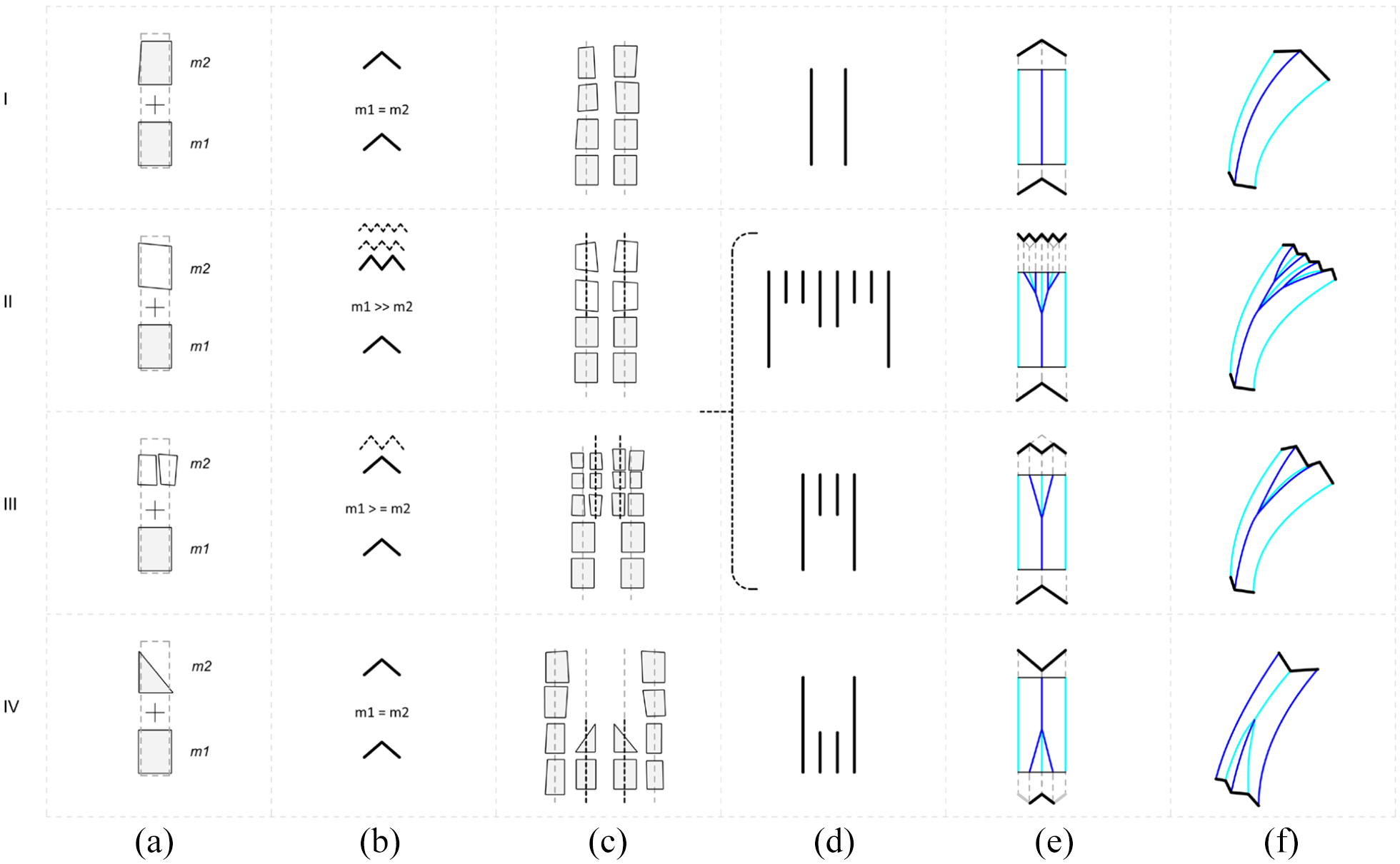
Tectonics Local Object Placement Rules: (a) object selection, (b) material stiffness requirements, (c) object placement strategy, (d) linear surface abstraction, (e) 2D surface topology implication, and (f) 3D surface corrugation.
Each of the cases in Figure 4 is explained from local object scale to global implications through the following steps: (a) object selection for placement, (b) material stiffness requirements per piece, (c) object placement strategy for the following pieces, (d) linear surface abstraction, (e) 2D surface topology graph, and (f) 3D surface corrugation.
Connection logic
Several factors were considered when determining the connection type: (1) reversible connections as the key joining strategy, and (2) minimizing the overall number of joints. Therefore, a folded overlap with bolts was selected to join metal sheets. Staggering of pieces and replacing an object edge with a fold line reduces the number of joints and enables a one-sided lap to connect pieces, which also stiffens the arc ribs (Figure 5(b)). This connection was tested as two sheet metal prototypes in 1:1 scale: first with the same sheet metal sample, second with different sheet metal materials (Figure 5(c) and (d)).
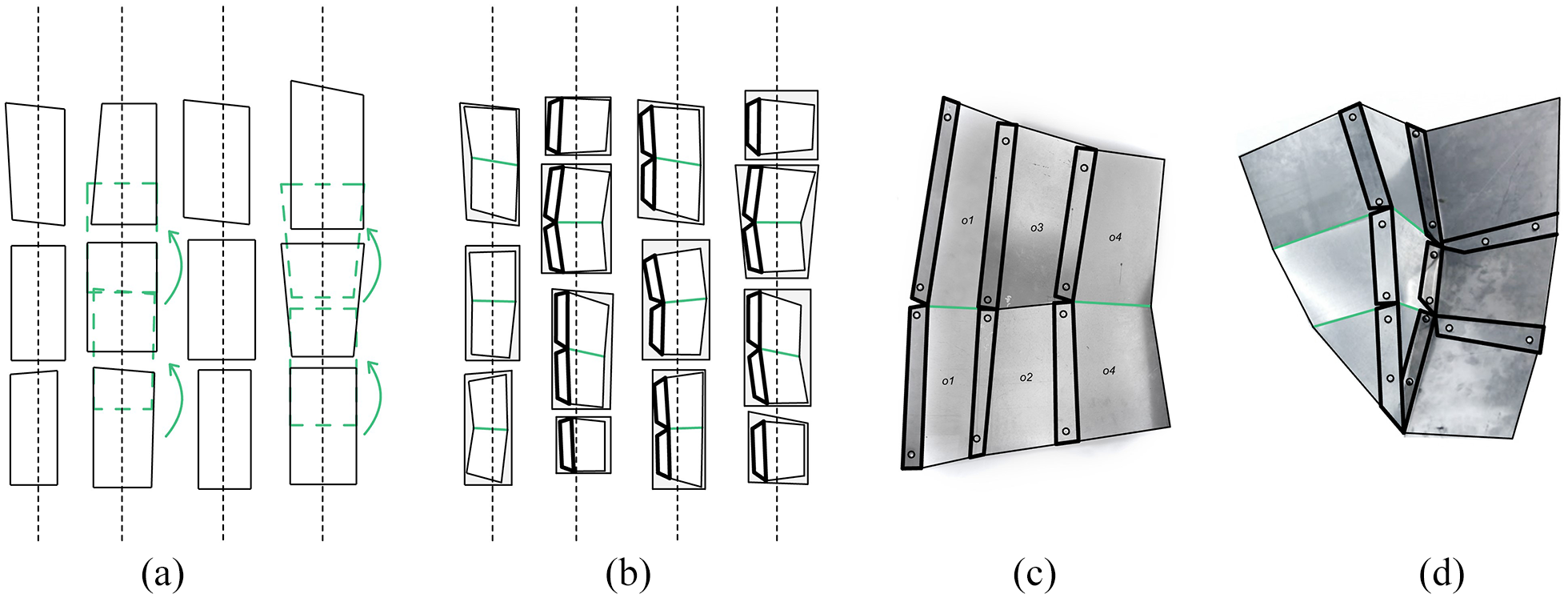
Connection logic: (a) basic object placement, (b) shifting and staggering, (c) prototype I single-sided joint, and (d) prototype II double-sided joint connection.
Computational design workflow
The project proposes a workflow where planar pieces of sheet metal and design parameters are inputs and the generative design algorithm would approximate and adjust the design surface based on the available material.
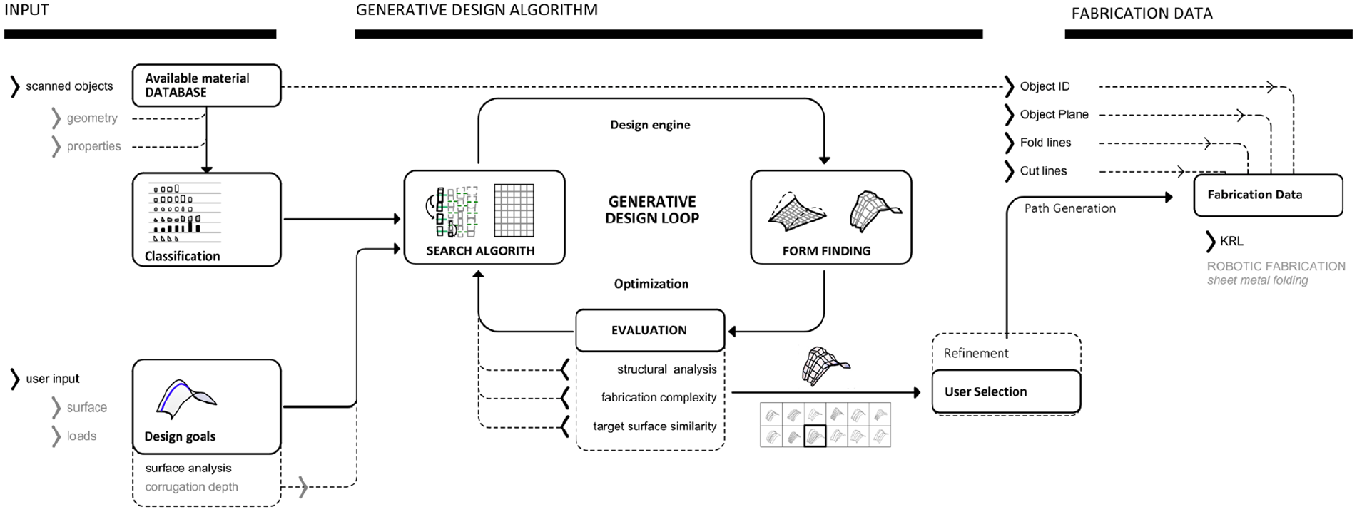
The computational workflow consists of three main parts; inputs, generative design algorithm, and generation of fabrication data. (Figure 6) The inputs for the generative design algorithm are the available material, design goals and rules. The generative design algorithm consists of material classification and a design loop which iterates through the following steps: (i) search algorithm - where material pieces to be used are selected, (ii) form-finding – where a 3D surface is generated, and (iii) evaluation and selection- where the solution is analyzed and rated. The last step triggers the next iteration of the design loop. The output of the algorithm is a set of possible solutions helping the designer explore the possibilities within the object constraints. Finally, fabrication data is generated for the selected solution.
Computational workflow.
The workflow was developed in the Rhino Grasshopper 30 environment. A custom GHPython script was developed for the search engine. Simulations were done using dynamic relaxation solvers of Kangaroo Physics 2 31 for form-finding, and Karamba 32 for structural analysis. The plug-in Octopus 33 was used to optimize the possibly conflicting multi-criteria of structural stability, fabrication complexity, material waste, and similarity to target surface with evolutionary algorithms.
Due to the large number of variables that make it impossible to calculate all the possible object arrangements, Accord C# Library was used in Grasshopper. It provided a basic interface for machine-learning-oriented data processing. Finding matching elements within multiple pieces and to form a matrix is a complex search problem that cannot be solved with blind search methods. 34
Arranging pieces in a grid can be seen as solving a constraint propagation problem with constraint satisfaction methods which reduces the search domain via techniques such as back-tracking, forwards-tracking and local search. 35 The search algorithm and form-finding make the design engine within the workflow as they generate a surface and approximate the target through a translation of search algorithm results for object placement into a 2D mesh graph which is then linked to 3D form-finding. The optimization with the design engine creates a generative design loop. The result is a set of solutions available for overview and finally user selection (Figure 6).
Inputs: Design goals and establishing a database of available material
The inputs for the computational workflow are the available object database and the design goals.
The digital object database was established by scanning material for geometry and by manually inputting material property data. The objects were scanned with an RGB camera and outlines were extracted and simplified as two-dimensional polygons by using OpenCV 36 in Grasshopper. From there, the main linear direction was determined as the longer axis of the objects to be used for placement direction. A recursive algorithm 37 determines the largest four-sided polygon that fits within the scanned outline (Figure 7(b)). This “virtual” polygon is used later on in the computational workflow. The geometries are divided into quad-like and triangular pieces based on the length ratio of the polygon edges. Material properties were manually assigned within the visual scripting environment Rhino Grasshopper as follows: (1) material thickness, (2) type of metal, as well as (3) color. (Figure 7(c)) Objects with lower material stiffness due to thickness are also assigned as pieces which can be partitioned and used for multiple surface fragments. The design goal is defined through a target Nurbs surface with defined anchors and spans with UV direction informing the object placement. An additional design input is the loading condition. The input surface geometry is analyzed to determine the ideal corrugation depth. This value is used to start the search process in the following step.
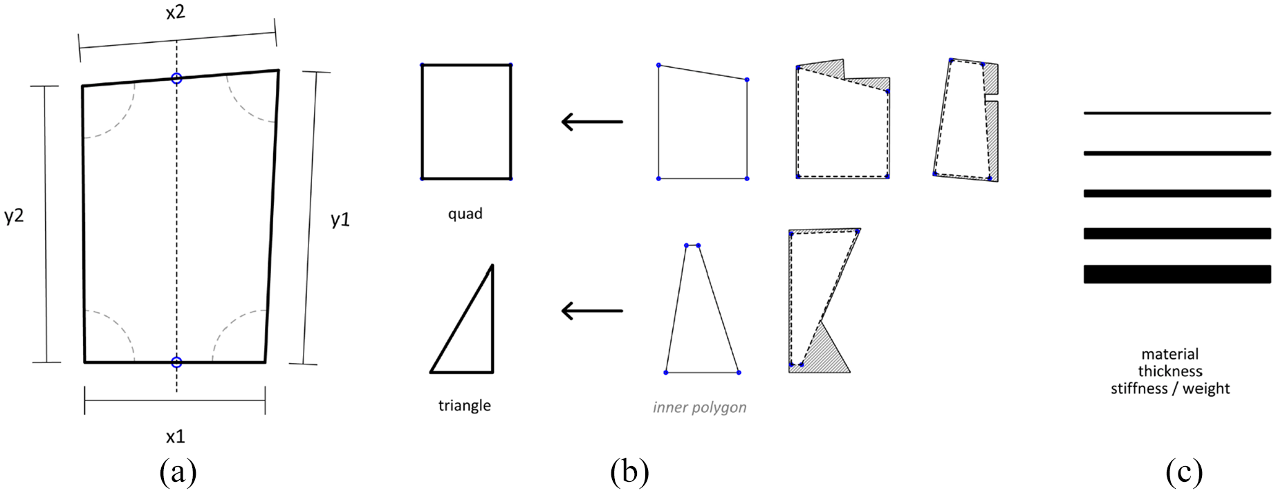
Object data and classification: (a) available material, (b) geometry classification, (c) material properties.
Generative design loop
The design engine consists of a search algorithm for object grouping and form finding. The grouping algorithm searches for corresponding geometry and properties of objects based on tectonic logic. It outputs a mesh graph which is the basis for form-finding and three-dimensional surface approximation.
Search engine grouping
The search engine determines the object placement and groups objects by situating them inside a virtual grid/matrix. Based on the tectonics each piece is constrained by its neighbor as their width and length need to match within a set tolerance range.
The algorithm performs the following steps: (1) local search for domain reduction and (2) backtracking. The local search initially groups objects based on their widths. This limits the number of pieces to be looked at when choosing a potential match. Backtracking is used when the algorithm cannot find a match. Each time backtracking occurs, the previously selected pieces are eliminated from the list of potential match candidates. The algorithm follows a hierarchic list of tectonic rules to determine further match options when there is no solution (Figure 8).
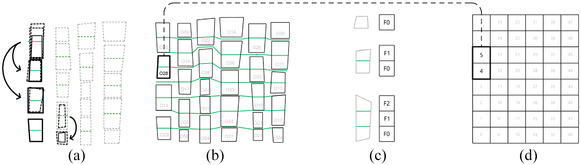
Search engine: (a) search algorithm, (b) resulting object placement, (c) mesh face assignment, and (d) mesh graph.
The search algorithm determines the length and number of connections for each piece, in which the goal was to find the corresponding length between neighboring strips from the middle of each object to another. In the search algorithm the matrix is represented as a list. The objects are placed iteratively, matching widths and lengths within the set tolerance, and adding pieces until the added dimensions of arranged pieces match the target required by the surface. Based on the tectonic logic, the algorithm staggers the objects; when a new sub list is started it has to match the length between the mid-points of the neighbors in the U and V direction. (Figure 8(a)) In that way the subdivision of the placed object or its fold-line is defined. (Figure 8(b)) The output of the search engine is a digital matrix with a nested list data structure. This matrix is later used to translate the objects into a three-dimensional surface approximation as it defines the basis of mesh subdivision and topology (Figure 8(d)).
Form-finding
A digital form-finding tool was developed to generate the possible mesh geometries. The matrix result of the previous grouping step is used to generate a mesh graph and later topology. The mesh graph is a representation of the connectivity between pieces as each object, or specifically each object segment, directly corresponds to a specific mesh face index. (Figure 8(d)) The search algorithm already determines the fold lines which in this translation means that no fold lines represent a single mesh face, one-fold line two mesh faces, and so on retrospectively (Figure 8(c)).
Following the mesh graph generation, a set of both 2D and 3D constraints and goals were defined for form-finding in Kangaroo (Figure 9). The 2D parameters are linked to the actual objects, while the 3D parameters are linked to design inputs, the target surface and approximated structural fold. The 2D constraints are: (1) boundary of the actual objects, (2) offset value for the joint overlap connections, (3) line length ratio, and (4) length matching of lines between neighbor pieces as this directly translates to mesh edges. The 2D goal is maximizing object usage, which leads to minimizing waste (Figure 9(a)). The 3D constraints are: (1) set anchor points, (2) object planarization, and (3) definition of mountain and valley folding behavior. 38 The 3D goals are: (1) pull to surface, (2) to achieve a smooth corrugation through 180 angle between each polyline segment, (3) fold line and angle goals for corrugation. This link between 2D and 3D goals and constraints allowed for a better understanding of the relationship between geometry and object usage trade-off. (Figure 9(b)) The result of the form-finding process is a relaxed 3D mesh and the corresponding 2D objects with defined cut and fold lines within the original object boundary.
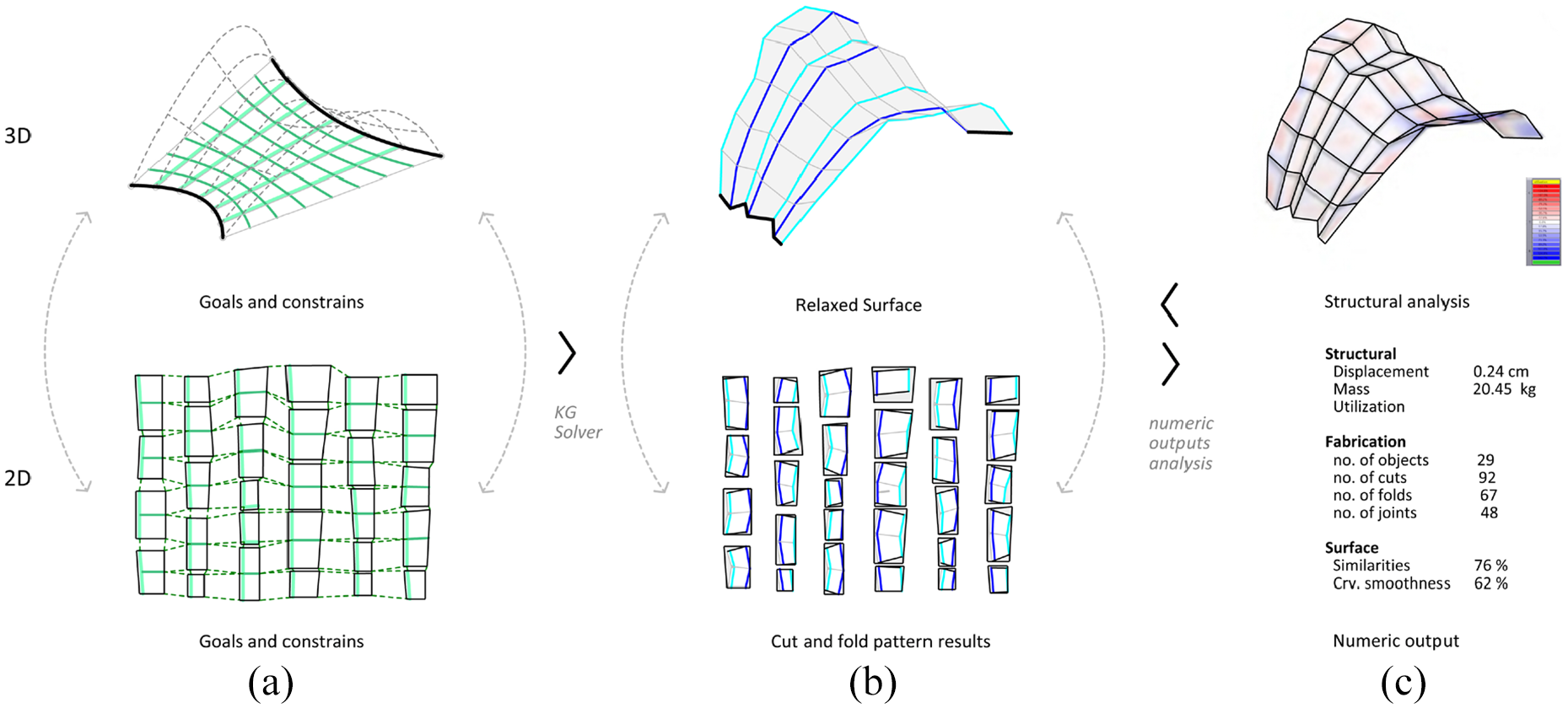
Form finding and evaluation: (a) input, (b) result, and (c) evaluation.
Evaluation and selection
To evaluate the quality of results structural analysis in Karamba 32 was applied, as well as custom Grasshopper 30 scripts calculating material waste, fabrication time and complexity (number of cuts and folds), and similarity to target surface. These numeric values were the evaluation criteria to rate each option.
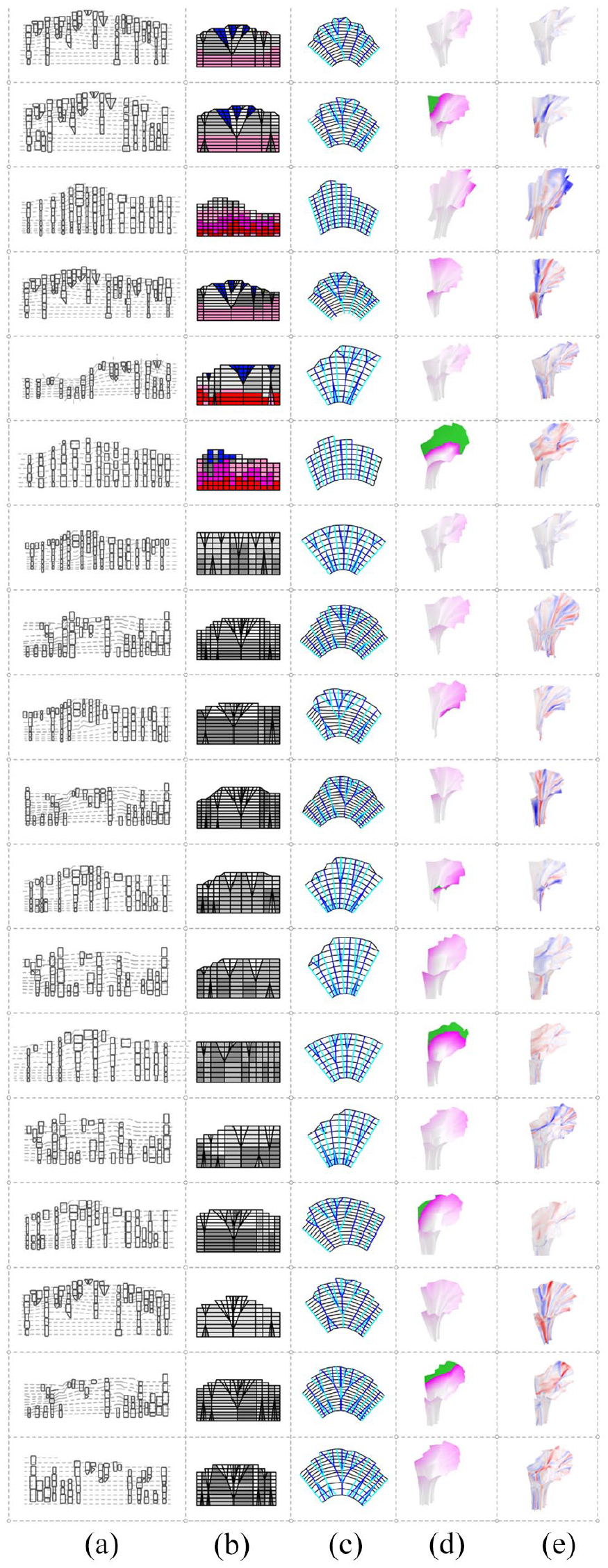
Structural analysis included simulating the model under self-weight and external loads and correlating mesh faces to object material properties; values for thickness and type of metal. The main evaluation factors for the structures’ load bearing capacity and efficiency were the deflection value and self-weight (kg) of the structure. Optimization of the multiple evaluation criteria is performed by looping through generated meshes and updating grouping with the multi-objective search engine Octopus. 33 The genetic solver in Octopus triggers the next generation of grouping. This loop enables generation of different surface approximations (Figure 10).
Single curved surface approximation resulting mesh topologies I-V: (a) generated surface, (b) mesh topology, (c) mesh graph with material distribution.
The best solutions are recorded, sorted and displayed using a built-in visualization within Octopus. To view the options the user can access our custom-built visualization in Rhino displaying both the 2D objects and the corresponding 3D mesh with the numerical evaluation values.
Fabrication methods/manufacturing
Robotic fabrication
The robotic fabrication methods consist of strategies to deal with unknown material, empirical testing for determining material behavior (in this case spring back), scanning and sensing for object recognition, and hardware development of a folding setup and a robotic end-effector to recreate an industrial sheet metal folding process. The workflow is as follows; all pieces are pre-scanned and marked to be used in the computational workflow before the fabrication process, followed by piece recognition, robotic fabrication, and finally assembly. As industrial waterjet processes make it difficult to account for different material properties for each piece of sheet metal, the fabrication workflow consists of both robotic fabrication and manual processes. Tasks requiring precision and strength such as material localization, marking and folding were executed by a Kuka industrial robot, while drilling and cutting of the objects as well as assembly were executed manually with an accounted tolerance (Figure 11).
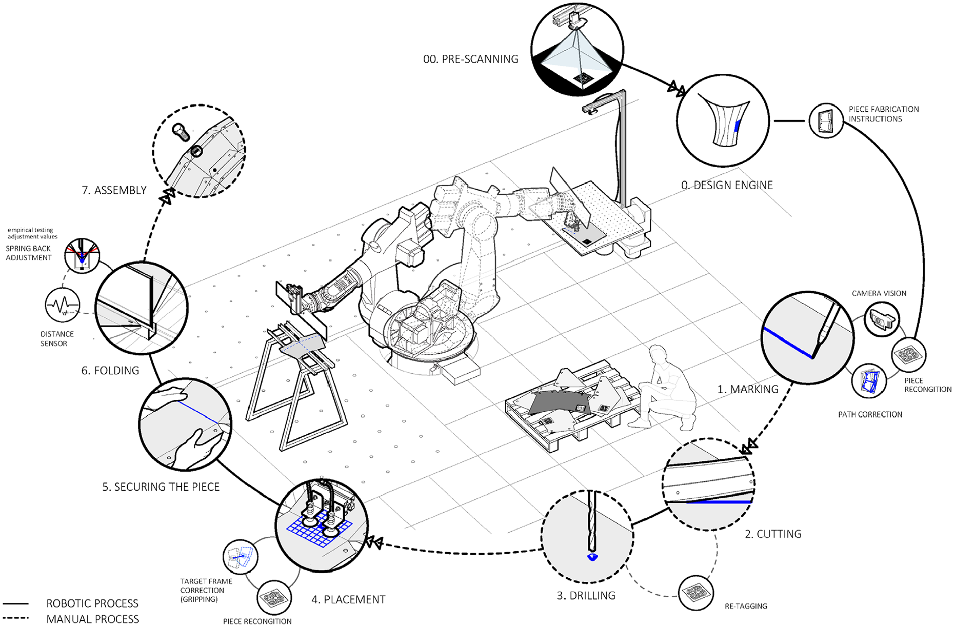
Robotic fabrication workflow.
Robotic fabrication setup
The robotic fabrication workflow consists of the following steps: piece recognition and robotic marking, manual cutting and drilling, piece recognition and robotic gripping and folding, and finally assembly.
A bespoke end-effector was developed to carry out these tasks. It consists of three separate tools to perform the functions as distinct operations; an automatic center punch spring screw for metal marking (AFUT) (Figure 12(b)), a suction cup vacuum gripper (Figure 12(c)), and a steel plate with a custom profile for folding (Figure 12(d)).
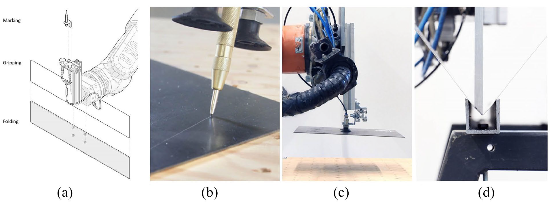
End effector and main robotic operations: (a) end effector, (b) marking, (c) gripping, and (d) folding.
The workspace consists of two workstations with different base coordinate systems; one for tracking and material recognition with a camera, and one for folding. The tracking station consists of a material placement area with a camera which is used for recognition and marking cut lines and drill points. The folding setup is based on the industrial press brake mechanism and the air bending principle which can accommodate different materials thicknesses and bend angles without retooling. 39 Although less accurate than other folding methods, this setup makes it suitable for dealing with different materials within one production line. Here, a U-shaped steel profile acts as the bottom die while a steel profile mounted on the end effector is used as the punch tool. The profile of the punch tool defines the bending radius while the downward stroke of the end effector defines the bending (folding) angle.
Material properties
Due to the unpredictability of material properties and behavior of reclaimed objects, it was important to establish both bending radius and spring back values for different sheet metals for fabrication. This was done through empirical prototyping where each sample of material and thickness was tested on the same folding setup with the same initial stroke and target folding angle. As expected, materials behaved differently and the resulting angle values were recorded and used to determine spring back adjustment values through repeated testing. (Figure 13) These values were used to adjust the robotic stroke movement within KRL to achieve the target folding angle based on the individual materials.
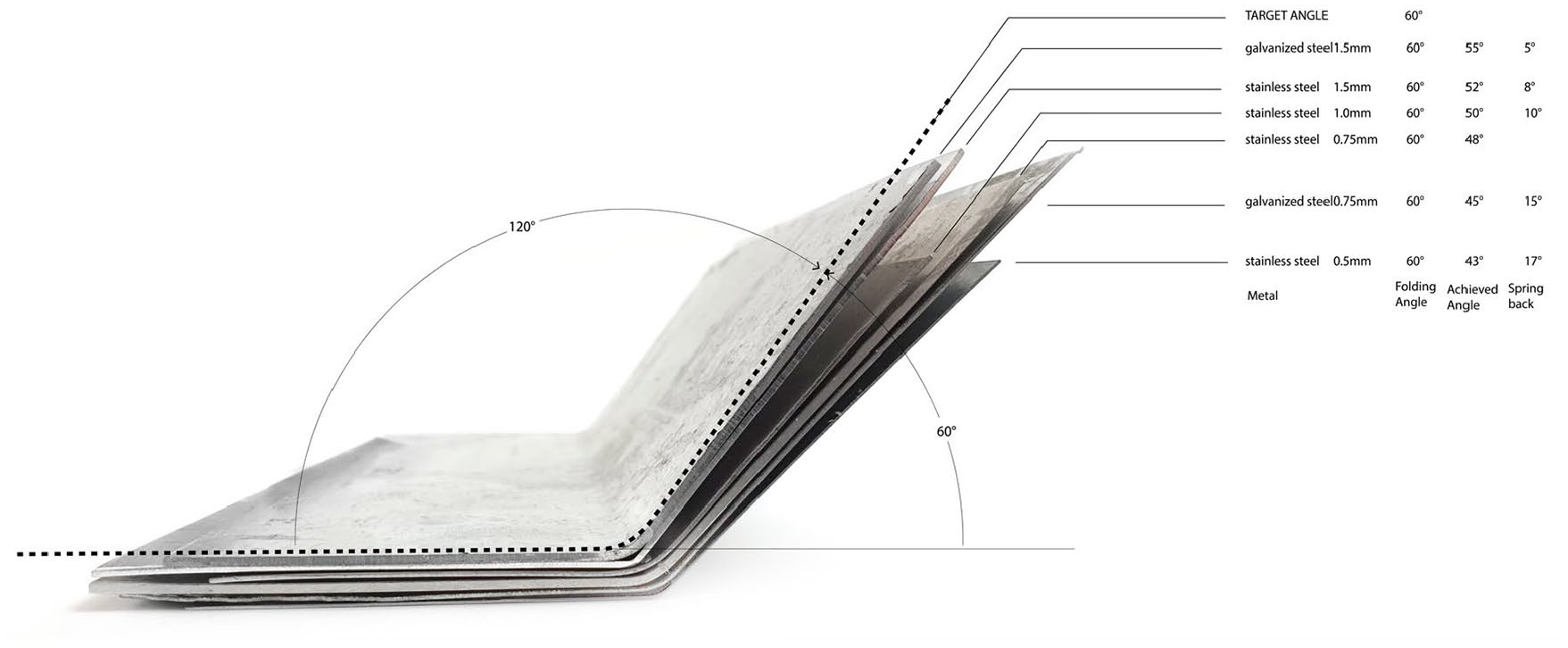
Material properties, spring back.
Material recognition
Material recognition is crucial when dealing with non-standardized materials in fabrication. In addition to the established outline extraction in the computation workflow, for the purposes of robotic fabrication fiducial markers 40 were attached to each piece of material in the pre-scanning step. The fiducial markers were used to save object ID, plane origin and plane orientation in relation to the outline to correctly locate the piece later during fabrication.
Robot control and communication
In conventional KRL path planning, the robot executes a predefined code for fabrication. This is based on the assumption that all pieces are standardized and therefore their position is also predetermined throughout the process. The fabrication of non-standardized pieces in this project was enabled through the Kuka Robotic Sensor Interface (RSI). With RSI real-time data exchange through serial communication is possible; ethernet packages are streamed via user data protocol over a network between the server, which handles data communication, the client, which is used for data processing and control, the robot, and in this project’s case a camera sensor 41 (Figure 14).
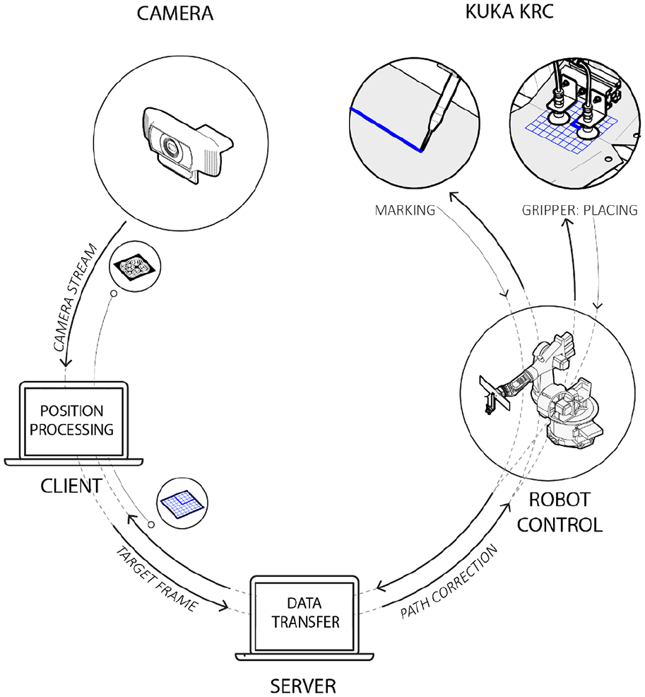
Object recognition & RSI workflow.
For object recognition an open-source cross-platform computer vision framework ReacTIVision 42 was used for fiducial marker tracking to get an up-to-date object location and orientation from the camera via RSI. The object ID was used to locate the fabrication instructions in KRL, while the plane information was used to create adjustment values in path planning. This process is used both for marking where the robot adjusts the path of the metal marker, and the folding operation where the objects are already cut, and the adjustment is used for material gripping. The gripping operation is one of the crucial steps not because of accuracy of material placement but because of material orientation which is crucial to ensure the correct folding direction. When using non-standardized material in the fabrication process mistakes in fabrication also mean that an object cannot be as easily replaced.
Demonstrator
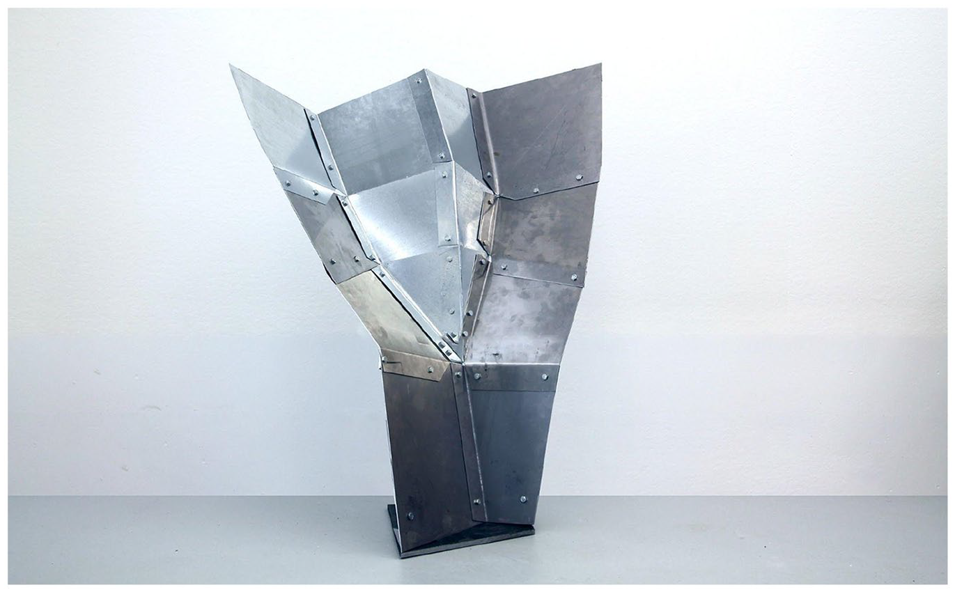
In the presented research the developed methodology was tested on two examples to test its applicability to different surface typologies; a single curved arch surface (Figure 9), and a double curved surface cantilever with different surface edge lengths ratios(Figure 15). In the latter, the structural typology requires a careful distribution of material based on its properties due to the self weight. 243 pieces of metal were cataloged and classified into four different material groups (galvanized steel, stainless steel, aluminum and copper) of four different main colors(copper, white paint, light gray, dark gray) with different thicknesses ranging from 0.5 to 2 mm. Geometrically, the majority of the pieces were quads with some triangular elements. The goal for the cantilever surface was a corrugation of approximately 40 cm at the support, based on a structural analysis under self weight load. The preferred design solution was selected from the top scores. (Figure 16) A refinement step was performed to smoothen the selected result corrugation. As a demonstrator, only a part of the selected solution was robotically fabricated (Figure 17).
Final design: (a) grouping, (b) mesh graph, (c) mesh topology, (d) 3D surface with deformation, and (e) utilization.
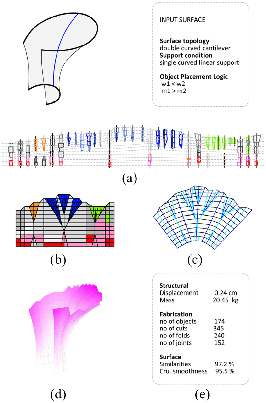
Surface generation: (a) grouping, (b) mesh graph, (c) mesh topology, (d) deformation, and (e) utilization.
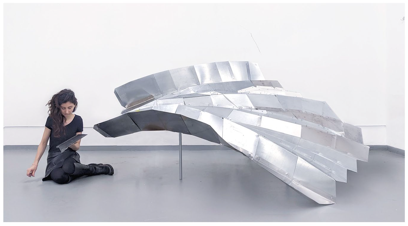
Robotically fabricated demonstrator segment.
Discussion and Conclusion
Discussion
The work presented in this paper introduces a novel methodology integrating generative design, robotic fabrication, and unknown material. The computational workflow for designing with non-standardized material demonstrated that any planar sheet of material can be used as an input to approximate a target surface. The results show a variety of non-predetermined topologies informed by the available stock material. The robotic fabrication workflow incorporates sensing as a crucial aspect of working with non-standardized materials. Nonetheless, some aspects of the research require further technical development.
The computational workflow shows potential by linking a recursive search algorithm for object placement, form-finding, and evaluation in a loop. However not all parts have been fully automated. More complex tectonic rules such as branching for object placement were manually performed in the search algorithm to test the methodology. Another limitation of the search algorithm was its inability to mirror the objects which could better determine object placement and potentially lead to better object usage. The results showed that despite the ability to produce different mesh topologies further refinement was still necessary to achieve a greater degree of esthetics and user satisfaction. It is therefore necessary to add user preference into the optimization loop which could influence the value of the different goal strengths within form-finding and the ability to change the design intent to a greater degree. Future work could also integrate multiple solution generations within one iteration of grouping as an additional step as it is difficult to achieve a preconceived design when working with a finite number of available objects. The same grouping could generate different surfaces, but this would imply that there would also be more waste.
The developments in robotic fabrication successfully integrated material properties consideration into the workflow by accounting for different spring-backs. The key to enabling the use of non-standardized material in this scenario however would be to implement sensing also within the steps of recognition and folding. In the industrial press brake folding setup sheet metal bending happens with die and punch tools in order to control the material specific bending radius. 43 This makes the setup hard to use when dealing with changing material properties. However, press brakes with automatic tool changers with detection of sheet thickness and angle adjustment are already available on the market. 44 This would eliminate the need for test bending as adjustments of the initial bend angle can be automatically corrected, providing a precise folding angle. These developments show that there is already technology in an industrial setup for fabrication of non-standardized material but that there is no support structure as the processes are linked to cutting and forming from standardized stock material. An additional constraint in the fabrication setup was Kuka payload which limited the thickness of the sheets that could be robotically folded within the project setup. For this reason, 2mm steel and aluminum sheets were folded manually with a bending brake setup. Using an industrial automated robotic press brake folding setup would extend the possible material range.
In order to increase the stiffness of the overall system the joints will be optimized in future work using integrated “form-fit” connections which are laser cut into the sheet edges.
Currently the project computationally deals with 2D metal sheets and 2D database information. Robotically press brake folding is used as a method of fabrication, in addition to manual shear scissor cutting. Future work could extend this method to the more readily available waste of hydro- and press formed 3D metal sheets. The new availability of 3D scanning and laser cutting techniques may give access to this extensive source of material for reuse.
Conclusion
This paper presented a novel computational and fabrication methodology that allows designing and building with non-standardized as-found sheet metal. The computational workflow takes the restrictions of the available material and the design aim as input, it generates solutions that satisfy both the design goals and the availability constraints. The output is a generation of different corrugated shell topologies, showing a direct link between availability based on geometry and material properties of reclaimed material and design possibilities.
These methods could be applied at different scales (architecture, design, products, etc.) depending on the size of the leftover material and the fabrication setup, as well as other material systems within the scope of planar sheet material and shell structures. The project highlights the potential of combining new technologies of generative algorithms and robotic sensing in design with non-standardized material. It calls into question the typical linearity of design processes and pre-determinacy of design solutions. Although not explored in this project, further development of the computational methods could enable a greater degree of designer interactivity to make a more direct dialog between resources and design goals.
Footnotes
Acknowledgements
The project was developed by the first authors within the ITECH MSc program “Integrative Technologies and Architectural Design Research” offered by ICD and ITKE at Stuttgart University. The authors would like to thank Zhiqi Lin for help with the search algorithm, H.P.Kayser company and metal workshop facilities of University of Stuttgart for providing the project with leftover sheet metal, and Julian Lienhard for support and discussion. The research has been partially supported by the DAAD.
Declaration of conflicting interests
The author(s) declared no potential conflicts of interest with respect to the research, authorship, and/or publication of this article.
Funding
The author(s) disclosed receipt of the following financial support for the research, authorship, and/or publication of this article: The authors Hana Svatoš-Ražnjević, Jan Knippers and Achim Menges acknowledge the support by the German Research Foundation DFG under Germany’s Excellence Strategy – EXC 2120/1 – 390831618.