
Abstract
Gastrointestinal surgery using a stapler is usually associated with tissue damage, anastomosis leakage, bleeding, and other complications, which is one of the effective methods for treating digestive tract cancer. The cutting properties of staples and the tissue damage occurring in the process of stapling porcine esophageal and gastric tissues have been evaluated and a new type of stapler has been designed. Since different structural and mechanical properties esophageal and gastric tissues layers, the puncturing force exhibits a fluctuating trend. Compressive stress caused by the bending of the staple legs can lead to the destruction of the vascular network inside the tissue, tissue deforms and tears. Finally, a staple with an internal incision arc (IIA) tip is designed, which meeting the performance requirements.
Introduction
Gastrointestinal cancer is a disease with very high incidence and mortality rates, and the main form of treatment is surgical reconstruction of the digestive tract. In recent years, the stapler has been the critical surgical instrument used in digestive tract reconstruction, which has extensively promoted the development of digestive tract reconstruction methods. Compared to traditional manual suturing, staplers can significantly shorten the operation time, minimize tissue damage, effectively reduce the complications of the surgery, and are widely used for the anastomosis of digestive tract organs and tissues. Nevertheless, there are still many problems associated with the structure, function, and use of the stapler,1–3 including poor staple forming, inability to strike, incomplete firing, damage to parts, and component shedding, 4 which may result in significant complications after anastomosis. 5 To this end, it is crucial to investigate the deformation process of staples, reduce anastomosis injuries, and optimize the staple structure.
Hümér Hültl 6 invented the first gastrointestinal closure stapler, which used staggered staples with a “B” shape similar to anastomosis spikes. The “B” type staple combines two layers of tissue to achieve a stable, relaxed, and reasonable effect beneficial to the healing of the anastomosis tissue; thus, in the clinic, “B” type staples are mostly used. In recent years, the circular section of the “B” type staple was changed into a rectangular shape to allow it to bend more reliably. Ethicon’s 2019 electric circular anastomosis featured the “3D Stapling Technology,” which uses an off-set closure of the anastomotic staple to distribute the compression evenly throughout the anastomosis, thereby reducing the possibility of potential anastomotic leakage.7,8 This was followed by “D” type anastomosis staples for low-grade colorectal surgery 9 and “mouth”-like skin anastomosis staples. However, currently, staples are designed primarily based on the level of use function and the damage caused to the tissue during the stapling process is not actually taken into consideration. Tissue damage can affect the healing of soft tissues, the restoration of the operation site, and even the regeneration of organs. 10 Son et al. 11 reported that, in the case of tissue edema, unintentional over-compression occurs, leading to unacceptable tissue damage. Zhou et al. 12 investigated the changes of the intracellular and extracellular fluid of small intestinal tissue under the action of a staple, and found that when the small intestinal tissue is compressed to a thickness of less than 0.54 mm, the ring and longitudinal muscles will be broken and sparse. Currently, the research on biological soft tissue injury is mainly focused on injuries caused by instrument clamping on tissue,13,14 while there is limited research on the type of tissue damage and the effect of the tissue injury during stapler closure.
Soft tissue anastomosis is the key to the quality of mechanical anastomosis, and its success rate is affected by several factors. Liaoyuan et al. 15 conducted a simulation analysis of the end-end anastomosis of large intestine tissue. They reported that when the anastomotic staple was struck at a 50%–60% tissue compression, the anastomosis was at its finest level. Gessica et al. 16 performed equine jejunum-cecal contralateral anastomosis using different diameter staples and found that staples with a diameter of 3.8 mm were better applied in the distal part. Contini et al. 17 compared the synthesis rate of three rows of staples with a varying-height stapler and a single-height stapler, and found that the arrangement of the anastomosis staples of the varying-height stapler could improve the success rate of forming. Jinhua et al. 18 investigated the effect of the staple alignment on the quality of soft tissue mechanical suturing surgery. When the number of suture staples was 3, the row spacing was 1; at 25 mm, the effect of mechanical suturing of blood vessels was optimal. Masahiro et al. 19 found that, when the staple was pushed from the small intestine into the esophagus, the blasting pressure was greater than that of the staple, and concluded that the direction of stapling affects the strength of the anastomosis. Weimin et al. 20 reported that the stapler operation method should be changed based on the bi-phased compliance and creep of viscoelastic biosolids. These are all ways to increase forming by improving the interaction between staple and tissue; however, the mechanism of the stapler soft tissue force is not yet clear.
In this study, the soft tissue stapling mechanism and the staple formation process are investigated, the tissue morphological characteristics after piercing are observed, and the mechanical damage effect and typical characteristics of the staples on soft biological tissues are analyzed. Moreover, stress-strain analysis is performed on both staples and soft tissues. An IIA staple tip structure is developed to satisfy the piercing, forming, and tissue damage requirements and its performance is assessed by performing ex vivo animal studies.
Materials and methods
Experimental materials
Pig is an ideal model for studying anastomoses in the lower gastrointestinal tract, since they are monogastric and similar in anatomical features to humans.21,22 Fresh porcine gastric and esophageal tissues (transferred frozen from a slaughterhouse to our laboratory) were selected as the experimental material. Before the start of the experiment, the gastric and esophageal tissues were processed and cut into small pieces of 5 mm × 5 mm (Figure 1(a)). A tube-type digestive stapler, staple anvil groove, and staple used herein are depicted in Figure 1(b) to (d).
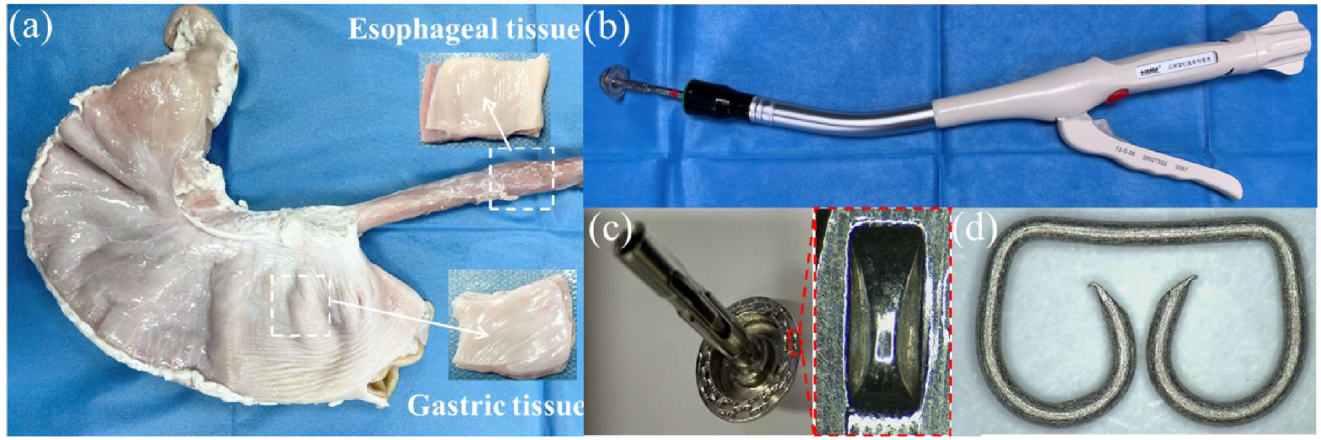
Tissue samples and digestive stapler used in the experiment: (a) gastric and esophageal tissues, (b) tube-type digestive stapler, (c) staple anvil groove, and (d) staple.
Experimental setup
The biological tissue puncture experiments were performed using a six-axis robotic arm (EPSON S5-701A, EPSON, Japan) with a repeat positioning accuracy of ±0.030 mm and a speed of 1–2000 mm/s (Figure 2). The puncture force during the piercing process was collected using a compact multi-component dynamometer (9119AA1, Kistler, Switzerland) with a force measurement range of 0–4 kN, the sensitivities of Fx, Fy, and Fz were set to 25.78, −12.66, and −26.26 pC/N, respectively, and the sampling frequency was set to 100 Hz. The observation of the structure before and after the forming of the staple, the recording of the staple forming process, and the observation of the surface morphology of the staple structure were all conducted using a Kunshan Gaopin 4 K microscope, with a measurement accuracy of 0.001 mm. Its optical magnification could be adjusted within 0.7–5.0×.
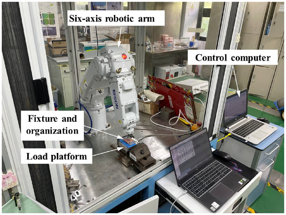
Tissue compression and puncture experimental platform.
Experimental methodology
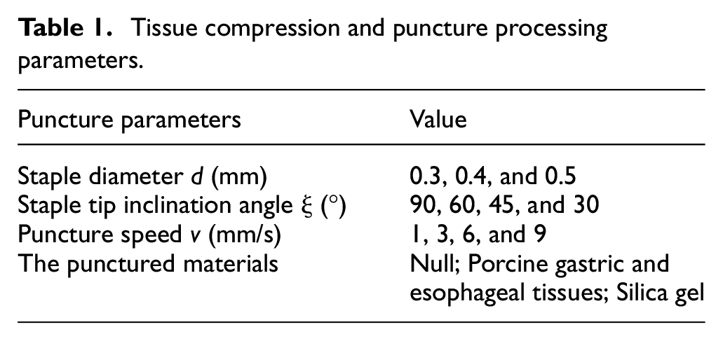
The porcine gastric and esophageal tissues were placed on the staple compartment, and a six-axis manipulator controlled the staple anvil to move toward the staple compartment. The force on the tissue was measured by the Kistler force measuring platform. Since the staple is a symmetrical structure, the simplified model in the puncture experiment used only a single side for a puncture, and the experimental puncture direction was vertical. The processing parameters are listed in Table 1. The experiment adopted a practical single-factor comparison method, and the fixed experimental parameters were the staple diameter of 0.4 mm, staple tip inclination angle of 45°, and puncture speed of 1 mm/s.
Tissue compression and puncture processing parameters.
In the staple forming observation process, the staple was pushed in silica gel or in the absence of tissue under the 4 K microscope, so the movement and deformation of the staple tip on the staple anvil groove and the tissue damage was observed. The method for preparing the anastomosis mouth sample is as follows: (1) the stomach and esophagus are detached, the esophagus end above the cardia is sutured and placed in the counter staple seat, and the purse suture is ligated. If necessary, the tissue of the esophageal stump is trimmed to avoid the presence of excessive residual tissue during anastomosis; (2) the staple compartment is extended into the stomach from all openings at the bottom of the stomach, and the puncture cone pierces the stomach wall and rotates out entirely; (3) after docking with the center rod of the staple seat in the esophagus, the adjustment nut should be tightened, the green sign of the appropriate range of staple forming is indicated in the window, and screw it to that green sign; (4) finally, the operator should hold the movable handle, hit the stapler, hold it for 15 s, release the staple after forming, and complete the cutting and stapling operations.
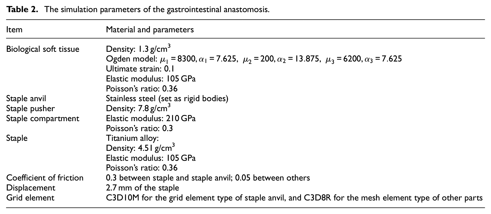
The staple forming model as shown in Figure 3(a), comprises staples, the staple anvil, the staple compartment, the soft biological tissue, and the staple pusher. For symmetrical models, 1/2 of the model was used to reduce the simulation time. The structure and material parameters of staple and staple anvil were shown in the Figure 3(b) to (d) and Table 2.
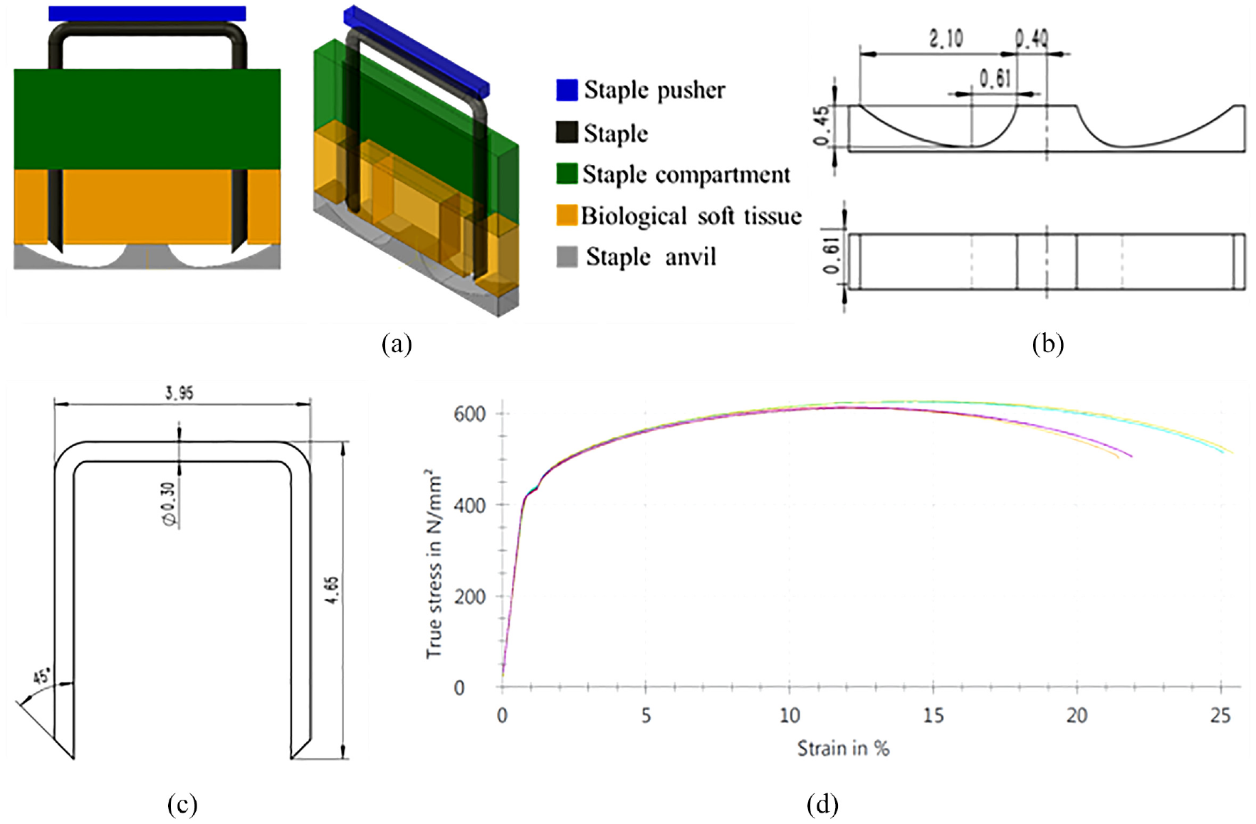
Staple forming simulation model: (a) the model of gastrointestinal anastomosis device, (b) the structure parameters of staple anvil, (c) the structure parameters of staple, and (d) the tensile stress-strain curve of titanium alloy used for the staple.
The simulation parameters of the gastrointestinal anastomosis.
To assess the effect of the shape of the stapler tip on the forming of the staple and the tissue, the shape of the left leg tip of eight staples was studied (Figure 4(a)–(h)). The Abaqus simulation software was used to determine the effect of different staple tip design parameters on forming performance.
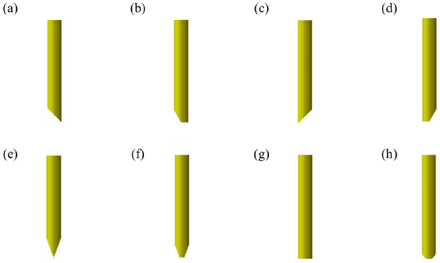
Staple tips with: (a) internal total incision (ITI), (b) internal half incision (IHI), (c) external total incision (ETI), (d) external half incision (EHI), (e) bilateral total incision (BTI), (f) bilateral half incision (BHI), (g) flat head (FH), and (h) round head (RH).
Finally, anastomosis pressure resistance performance and anastomosis tensile strength tests were performed according to the People’s Republic of China pharmaceutical industry standard YY/T 0245-2008 “General conditions of anastomosis (suture) clutches” and the YY/T 1797-2021 “endoscopic surgical instruments lumpectomy cutting anastomoses and components.”
Results and discussion
Soft tissue anastomosis
Biological tissue anastomosis process
As depicted in Figure 5(a) to (c), the tissue stapling process can be divided into a tissue compression stage (a), a tissue puncture stage (b), and a staple forming stage (c). Since soft tissues of the digestive tract, for example, the stomach and the esophagus, have viscoelastic mechanical properties, compression can fix tissues with uneven thickness to a specific thickness, thereby limiting their movement and facilitating the puncture. The tissue puncture stage is mainly the stage where two stapler staple legs pierce into two layers of separated tissue, the essence of which is to penetrate the tissue. In the staple forming stage, after the staple has passed through the tissue, the stapler staple legs are bent and deformed along the staple groove on the stapling anvil. After the anvil and the staple compartment are opened, the staple can still resist the rebound of the tissue. The stapler staple legs are pierced into the tissue twice; thus, the anastomosis staple connects the tissue tightly together, preventing the entry of the organ into the chest cavity through the gap between the two layers of tissue and closing the blood vessels around the anastomosis region.
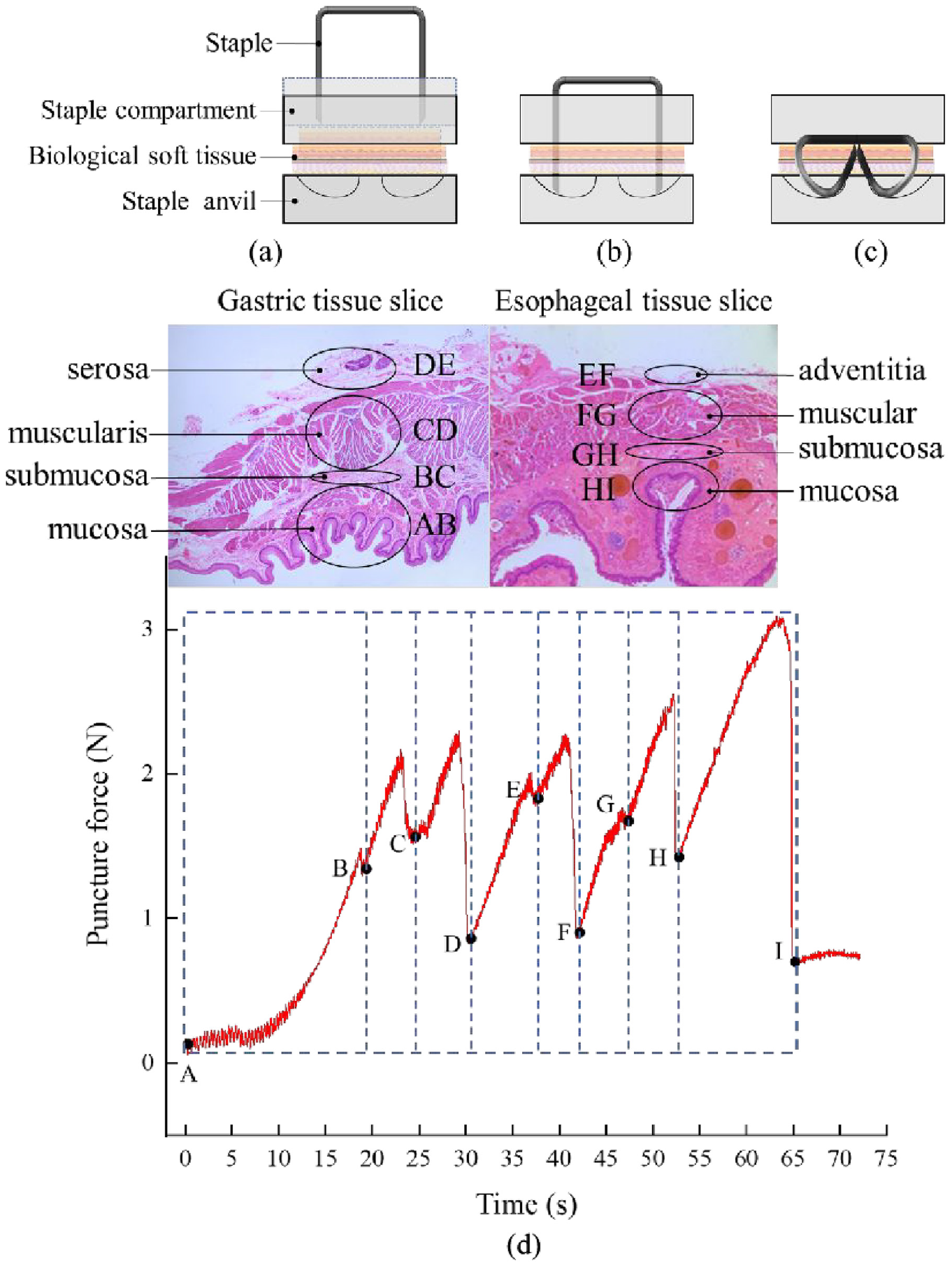
Biological tissue anastomosis process: (a) tissue compression stage, (b) tissue puncture stage, (c) staple forming stage, and (d) puncture force versus time curve of a staple piercing through gastro-esophageal tissue when the puncture velocity was set to 3 mm/s.
The stomach and the esophagus are multi-layer composite structures, and each layer has different structural and mechanical properties. Due to the presence of many intricate tissue fibers inside the tissue, the puncture force-time curve exhibited a fluctuating upward trend, as shown in Figure 5(d). During anastomosis, the gastric serosa layer corresponds to the contact layer with the esophageal adventitia layer, and the anastomosis staple passes through the gastric and esophageal tissues in turn. Based on the obtained curve, the puncture process can be divided into eight stages, which correspond to the gastric mucosa, gastric submucosa, gastric muscular layer, gastric serosa, esophageal adventitia, esophageal muscular layer, esophageal submucosa, and esophageal mucosa. The anastomosis starts to contact the tissue at point A. Then, the puncture force gradually increases, the tissue deforms, and the force decreases sharply after reaching a peak value, indicating that the anastomosis has pierced a layer of tissue. Eight large fluctuations can be observed in the mechanical curve of the AH section, which fluctuate within the range of 0.8–3 N; after the puncture has been completed, the force value drops to point I, where the puncture force is only 0.5 N.
Figure 6(a) demonstrates the effect of staples with different diameters and tip inclination angles on the gastro-esophageal tissue puncture force. It can be observed that, under the same diameter, with the increase of the inclination angle, the puncture force gradually decreases. Moreover, the larger the diameter, the more obvious the force reduction. This is attributed to that, the larger the inclination angle of the staple tip, the smaller the contact area with the tissue at the staple tip, and the sharper the staple tip. Under the same inclination angle, the puncture force increased gradually with increasing staple tip diameter, and the smaller the inclination angle, the more obvious the force increase. As Figure 6(b) shown, It can be observed that when the speed was increased from 1 to 9 mm/s, the puncture force decreased gradually from 3.1 to 2.2 N. Therefore, the puncture force decreases with increasing puncture speed. However, compared to that of the staple diameter and tip inclination angle, the impact of the puncture speed is small. Consequently, the optimal design of staple structure is an essential factor for improving tissue anastomosis.
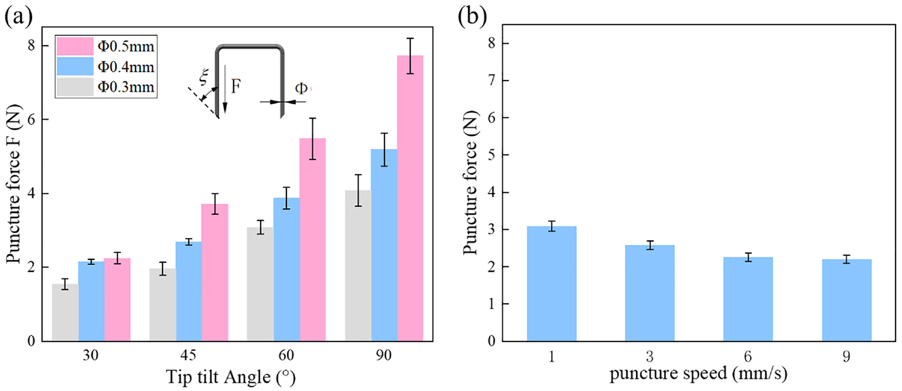
Factors affecting the puncture force: (a) Effect of anastomosis staple diameter and tip inclination angle on puncture force and (b) Effect of puncture speed on puncture force (diameter of 0.4 mm and an oblique angle of 45°).
Deformation process of staples
Figure 7(a) to (f) show the process of a staple air-punching under a microscope. Figure 7(g) depicts the staple tip force analysis of the forming process of Figure 7(a) to (f). In addition to the pressure exerted on the staple pusher, there are tissue friction, extrusion forces, cutting forces, and staple anvil groove support forces; all these forces combined lead to staple forming. In the forming process, the staple tip first touches the outer arc (Figure 7(a)), and as the staple is pressed down, its tip gradually slides inward along the outer arc, and its leg bends around the rounded corners at both ends of the staple beam (Figure 7(b)). Subsequently, the staple tip slides to the lowest point of the staple anvil groove, and its leg begins to undergo large deformation, forming a curved arc (Figure 7(c)). With the further downward application of pressure to the staple, the lower part of the staple leg gradually fits with the outer arc, and the point of action of the force becomes the arc of the staple leg. As a result, the force on the staple is transmitted to the arc of the staple leg, further pushing the staple tip to glide on the inner arc (Figure 7(d)). Then, secondary staple piercing occurs (Figure 7(e)). The tissue experiences a squeezing force at the secondary penetration region, and the movement direction after the staple leg has penetrated the inner arc changes with the bending of the staple leg and the extrusion of the tissue out of the inner arc. Finally, the staple gradually obtained a “B” shape, achieving the purpose of anastomosis (Figure 7(f)).
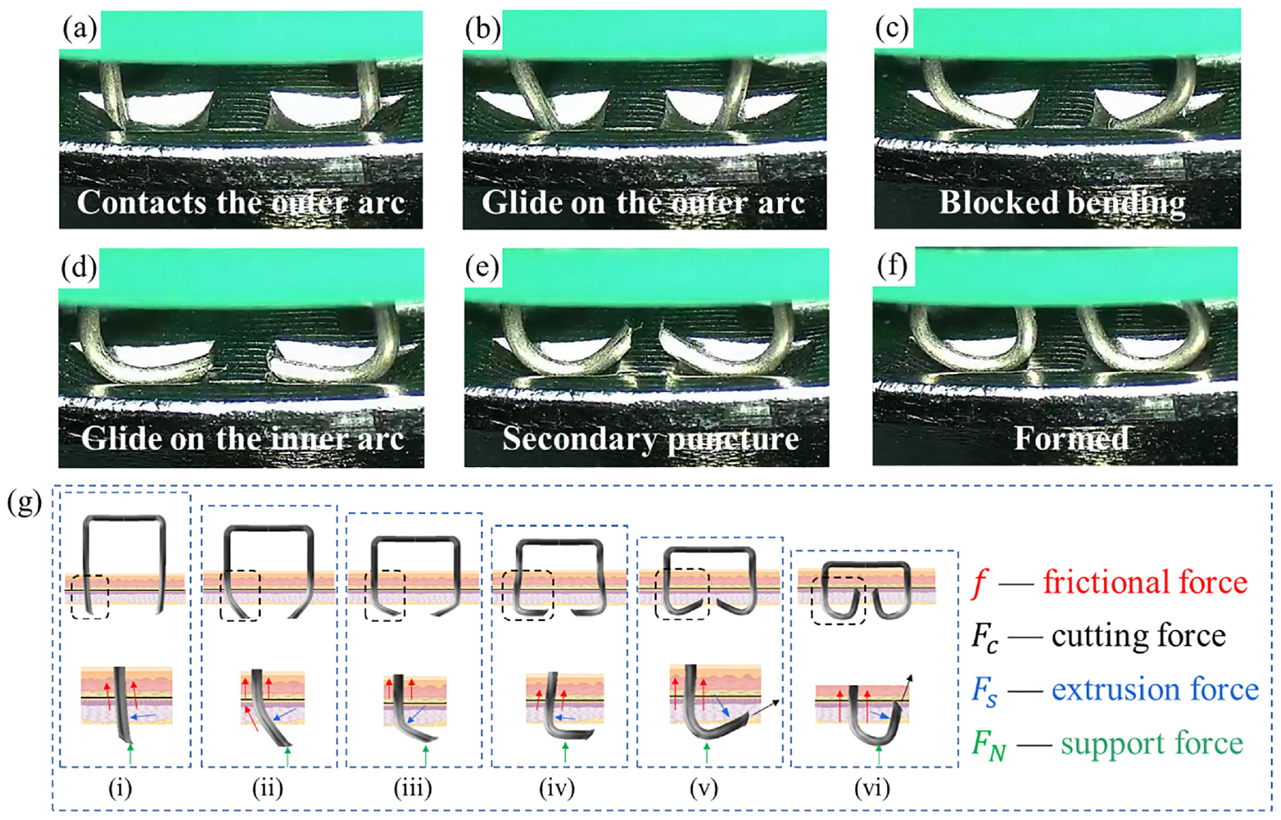
The process and force of anastomosis staple: (a) the tip contacts the outer arc, (b) Glide on the outer arc, (c) blocked bending; (d) glide on the inner arc, (e) secondary puncture, (f) molding, and (g) (i)-(vi) corresponding to (a)-(f) the force during the stapling of the staples to the tissue.
Figure 8(a) and (b) compare the experimental and simulation results. It can be observed that the deformed shape of the actual staple was the same as that of the simulated one. The high equivalent stress was found to be mainly concentrated on the curved arc of the staple leg and the point of contact between staple and staple anvil groove. Figure 8(c) and (d) correspond to the contours of the shear stress and equivalent plastic strain along the radial direction of the staple. It can be observed that the shear stress was concentrated on the arc of the staple leg, and the plastic strain of the staple was also concentrated on the bending position of the staple legs and tip. Figure 8(e) and (f) are cross-sectional views of the equivalent stress and strain distribution in the tissue, respectively. It can be seen that, after the staple has penetrated the tissue, the tissue is damaged, and the stress magnitude is higher than the fracture strength of the tissue. Finally, the maximum principal strain of the tissue after anastomosis was distributed evenly around the area in contact with the staple legs.
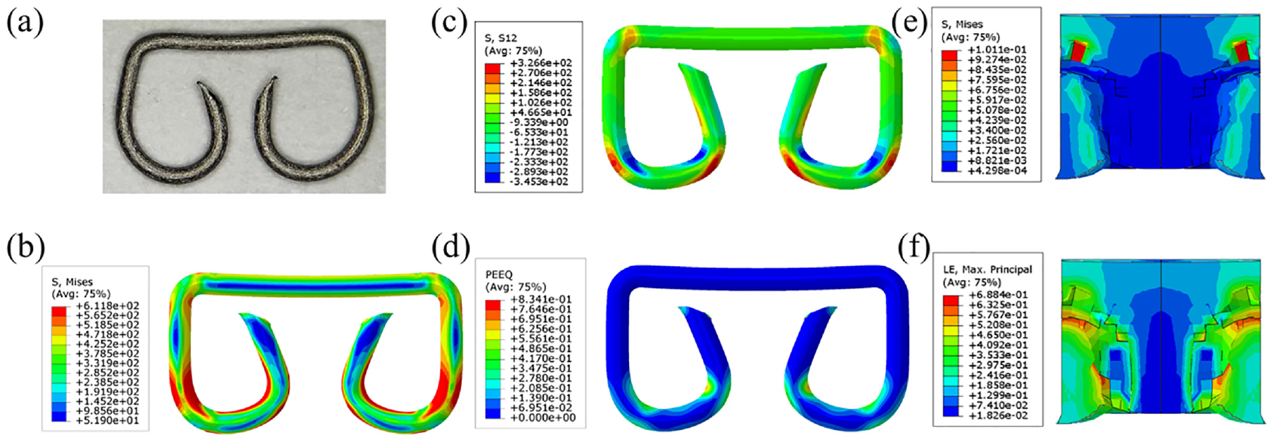
Stress-strain distribution on staples and tissue: (a) actual deformed staple, (b) simulated staple deformation and stress distribution, (c) shear stress distribution on the staple, (d) equivalent plastic strain distribution in the staple, (e) equivalent stress distribution in the tissue, and (f) strain distribution in the tissue.
Anastomosis injury of soft tissue
Figure 9(a) shows the compressed gastric tissue, deformed and concave at the location where the surface of the gastric mucosa layer is in contact with the anvil surface, while the part that is not squeezed appears as a bump. Due to the presence of blood vessels under the mucosal layer, the compression stress leads to the destruction of the internal vascular network. As illustrated in Figure 9(b), at the second passage of the staple through the tissue, the legs of the staples move along the inner arc of the anvil slot and bend toward the staple beam. The staple legs, which have limited degrees of freedom, can also better resist the rebound of the tissue, and the hole formed by the first piercing is further enlarged. In the frozen tissue sections in Figure 9(c), it can be observed that the hole left in the tissue after puncture has a water-drop shape, and the tip of the hole is due to crack expansion and deformation under the action of tissue elasticity. This type of tissue damage is the essential factor for anastomosis failure. Figure 9(d) and (e) demonstrate that, while the staples move along the staple anvil grooves, the two sides of the staple legs squeeze the tissue inward; subsequently, the staple tip pierces the anvil into the tissue twice and the staple tip cuts the tissue, causing it to tear and the crack to expand. As it can be observed in Figure 9(f), when the staple is bent and deformed into the tissue, a relatively long tear is formed, with the tissue surface having a more severe tear and obvious deformation. When the anvil and the staple compartment are separated and depressurized, the tissue returns gradually to its original thickness. On the contrary, the tissue limited by the staple does not bounce back to its original thickness, and a significant amount of tissue deformation remains (Figure 9(g)).
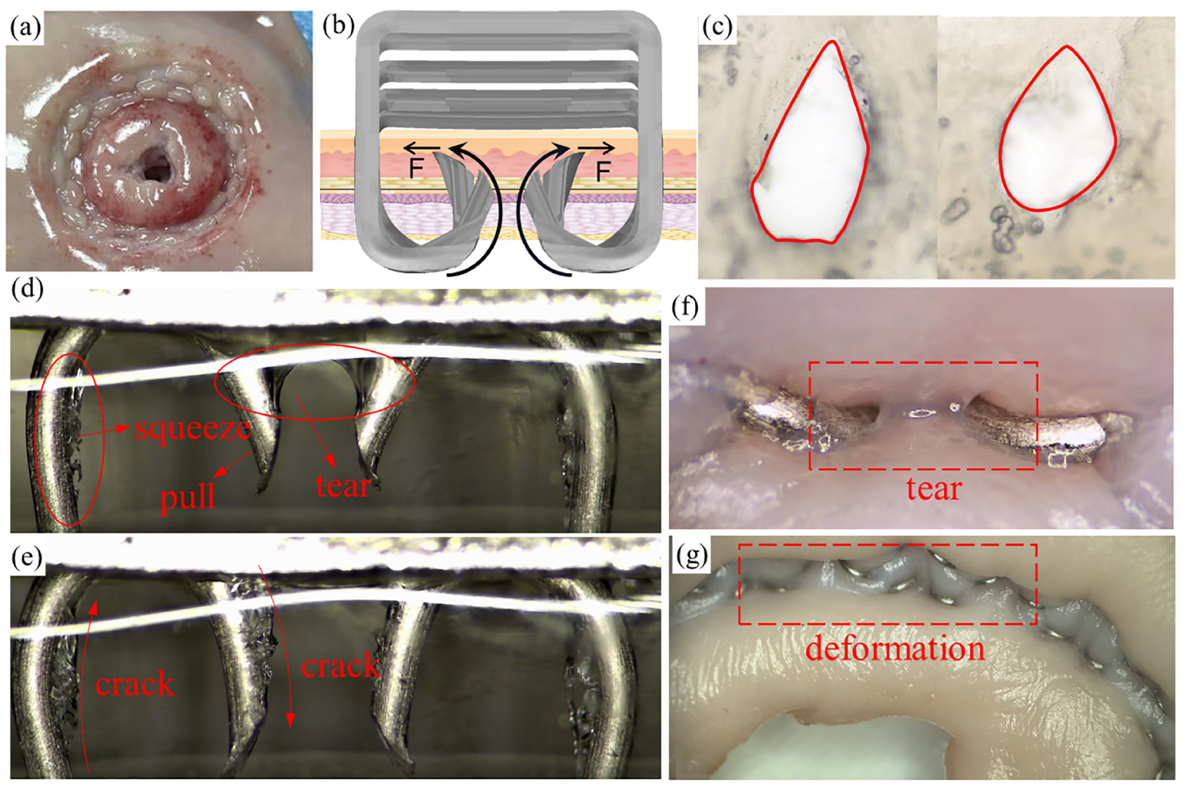
Anastomosis injury of soft tissue: (a) tissue compression damage, (b) illustration of secondary puncture injury of b-type staples, (c) tissue puncture injury, (d) and (e) internal tissue damage during forming, (f) external tear of the tissue after forming, and (g) tissue deformation after forming.
Optimal staple design and evaluation
Figure 10 shows the force-displacement curves of eight staples with different tip shapes (Figure 4). At the initial stage of contacting the anvil groove, the staple tip with internal total incision (ITI) has the lowest force. The staple tips with bilateral half incision (BHI), external total incision (ETI), and external half incision (EHI) are subjected to higher forces. During the forming process, the ITI, ETI, flat head (FH), and round head (RH) staple tip puncture forces appear smaller and more stable. The ITI and RH staple tips have relatively good forming performance since they are easier to fit with the arc of the anvil groove.
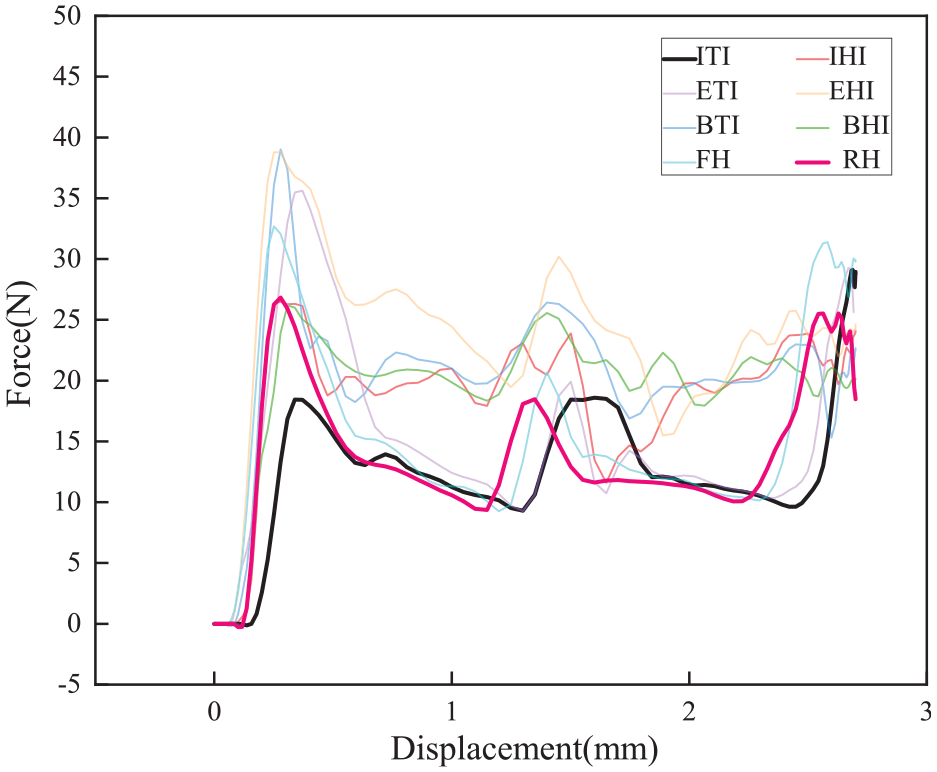
Force-displacement curves of staples with different tip shapes. Internal total incision (ITI); internal half incision (IHI); external total incision (ETI); external half incision (EHI); bilateral total incision (BTI); bilateral half incision (BHI); flat head (FH); and round head (RH).
When designing the staple structure, its puncture cutting performance and bending forming performance should be taken into consideration. Moreover, the primary role of the external row staple is to connect the two layers of tissue and provide a suitable anastomosis force. As depicted in Figure 11(a), the ITI staple tip has an oval cross-section, and the primary parameter for effectively piercing the tissue is the arc radius at the oval tip. In general, the larger the inclination angle of the staple tip, the easier it is to pierce the tissue; however, it is easier to deform after the tip of the staple contacts the anvil groove. As a result, the circular-arc cutting-edge of the section will continue to cut the tissue, and the crack of the tissue will propagate along the cutting-edge direction. The force of the RH staple tip piercing the tissue is higher than that of the ITI staple. Still, during the deformation process, the staple tip can completely fit with the anvil groove, forming line or surface contact, with almost no deformation at the staple tip. Therefore, by combining the characteristics and advantages of the ITI and RH staple tips, a staple with the above characteristics is designed, which is presented in Figure 11(b). It can be seen that the inner side of the staple tip has a moderately sharp structure, which is conducive to puncturing the tissue, while the outer side is arc-shaped, matching the staple anvil groove. Figure 11(a) and (c) compare the ITI and internal incision arc (IIA) staple tips. The inclination angle ξ1 of the IIA staple tip is larger than the inclination angle ξ2 of the ITI one; thus, the inclination angle at the edge is smaller. Sections A and B are the projections of the cutting plane at the tip of the staple. It can be observed that the arc radius of the IIA staple tip is larger than that of the ITI one; thus, the force is higher when puncturing and cutting the tissue.
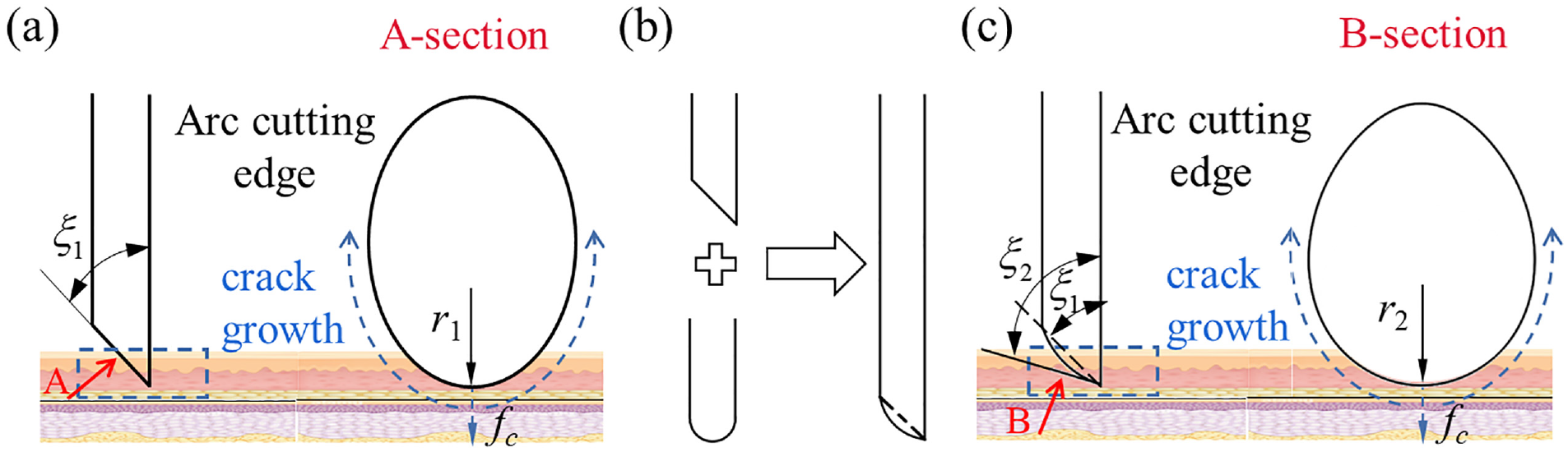
Optimal design of the anastomosis staple tip: (a) ITI staple tip, (b) tip optimization, and (c) IIA staple tip.
Figure 12(a) shows the maximum equivalent plastic strains of the ITI and IIA staple tips. Compared to that at the ITI staple tip, the equivalent plastic strain at the IIA staple tip is significantly lower, and the deformation at the staple tip is much smaller. Figure 12(b) displays the force-displacement curves obtained by simulating the ITI and IIA staples formed on the external rows of staples. On the same staple anvil, the two staple tips appear to bend essentially in the same direction, with a very tiny fluctuation in their value. Figure 12(c) shows the stress on the tissue when the ITI and IIA staples were deformed at several points during the simulated forming process. The staples with IIA tip exerted lower stress on the tissue at the initial and final forming stages and higher stress during the forming process.
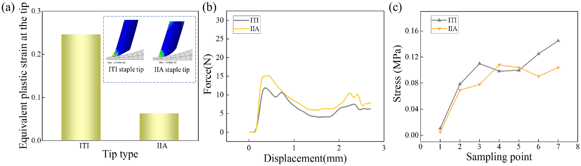
Simulation of the mechanical properties of the two staple tips and the tissues: (a) maximum equivalent plastic strain of the ITI and IIA staple tips, (b) force-displacement curve of the two staple tips, and (c) tissue stress of two staple tips.
New staples were manufactured using titanium wire by combining picosecond laser processing and sanding. Figure 13(a) depicts the ITI and IIA staple tips. The inclination angle ξ of the ITI staple tip was 30° and that of the IIA staple tip was 60°. The chart compares the puncture forces of the 0.4 and 0.3 mm diameter ITI and IIA tip staples. It can be observed that the puncture force of the IIA staple tip was higher than that of the ITI staple tip. Figure 13(b) shows the anastomosis curves obtained using the two staple tips, where it can be observed that the forces were roughly the same.
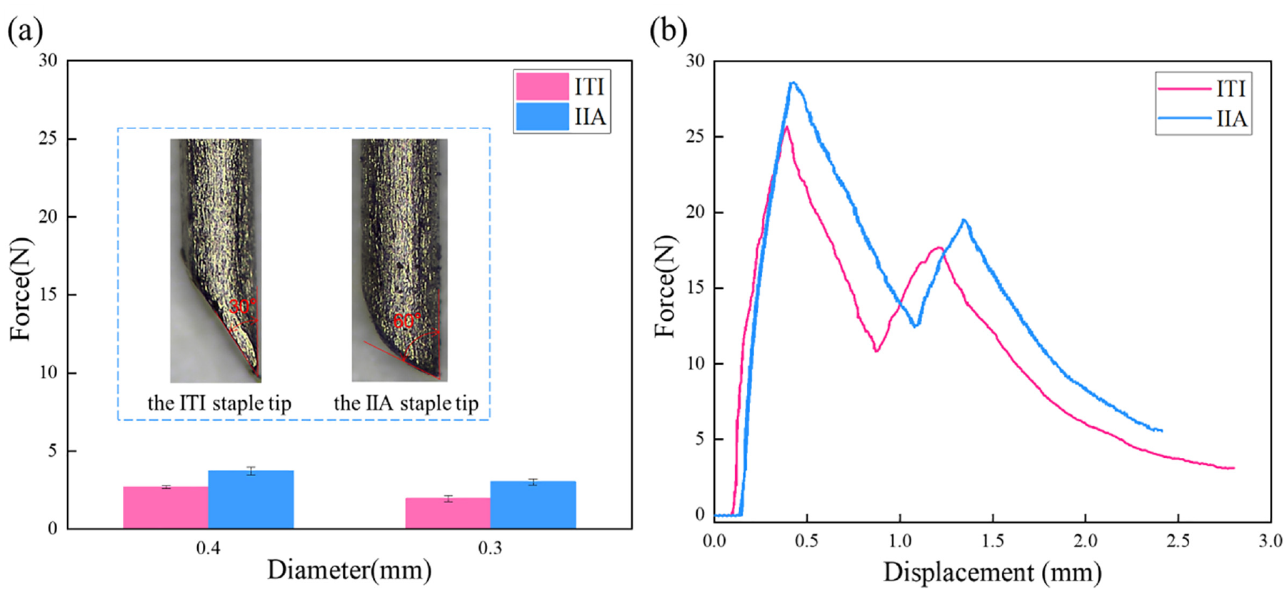
Comparison of the penetration force and anastomosis curves: (a) penetration force applied by two staple tips with different diameters and (b) anastomosis curves obtained using the two staple tips.
Figure 14(a) shows the gastro-esophageal anastomosis model, where it can be observed that the anastomosis stoma was flat and well-formed. Subsequently, the anastomosis pressure tests were performed, where the pressure was gradually increased to the specified value of 3.6 kPa, and then further increased to 8.0 kPa; each pressure level was maintained for 1 min. No water leakage or tearing occurred. When the pressure was further increased to 9.0-11.0 kPa, blisters began to appear in some of the anastomosis staple holes, but the amount of leaked water was minimal. These values exceed the industry standard of 3.6 kPa and meet the performance requirements. As displayed in Figure 14(b), the gastro-esophageal anastomosis model was clamped on a tensile testing machine and stretched under a displacement rate of 5 mm/min until the anastomosis was broken. The tensile force-displacement curve in Figure 14(c) indicates that the maximum tensile force was 32 N; then, the tissue was torn at the clamping position, and the force decreased gradually. In the experiment, no tear was observed in the anastomosis, which satisfies the tensile strength performance requirements.
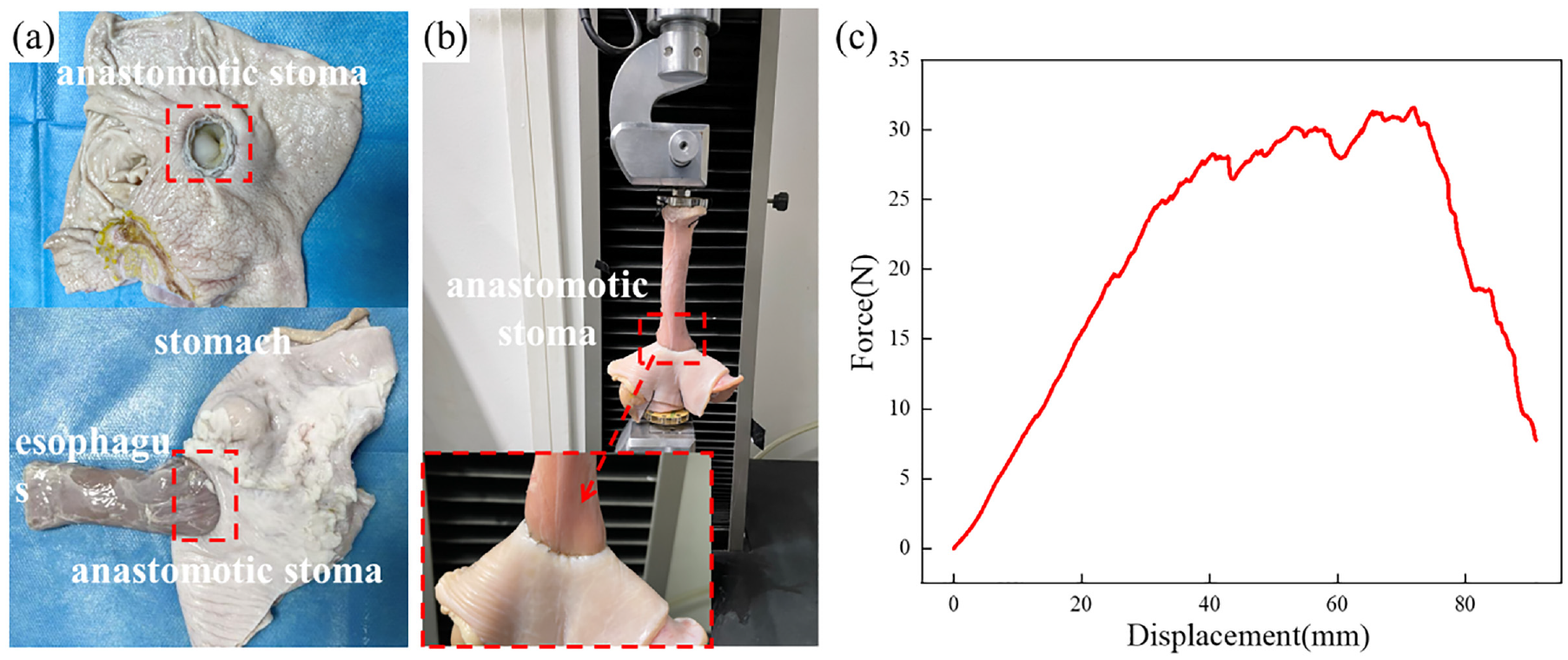
Performance evaluation of anastomosis staples: (a) anastomosis model, (b) tensile strength test of the anastomosis model, and (c) force-displacement curve.
Conclusions
The cutting properties of staples and the tissue damage occurring in the process of stapling soft tissues have been evaluated and a new type of stapler has been designed. The following main conclusions can be drawn:
The puncturing process can be divided into eight stages, which correspond to the gastric mucosa, gastric submucosa, gastric muscular layer, gastric serosa, esophageal adventitia, esophageal muscular layer, esophageal submucosa, and esophageal mucosa. Since each layer has different structural and mechanical properties and contains complex arrangements of tissue fibers, the puncture force curve exhibits a fluctuating trend.
In addition to the force exerted by the staple pusher, there is friction force with the tissue, extrusion force, cutting force, and the support force of the staple anvil slot, which combined lead to the deformation of the stapler.
Compressive stress can lead to the destruction of the vascular network inside the tissue. Tissue puncture deforms and tears the tissue. The bending of the staple legs squeezes the internal tissue, and the movement of the staple tip exerts a pulling force on the tissue, tearing it.
The puncture force of the IIA staple tip is slightly higher than that of the ITI staple tip, while its equivalent plastic strain is much lower than that of the ITI staple tip. The compression and tensile strength tests indicate that the IIA staple tip can meet the performance requirements.
Limitations and prospects
In this paper, only the characteristics of the anastomosis staple were preliminarily studied through ex vivo experiments, and have not been verified by animal experiments. In this manuscript, only gastric tissue and esophageal tissue were selected as experimental materials, and the differences in anastomosis characteristics between different biological tissues still need to be studied in the future. At the same time, there are still many problems in biological soft tissue anastomosis technology, such as the tethering effect of the anastomosis process, and the mechanobiological mechanism after anastomosis implantation.
Footnotes
Authors contributions
Xuan Dai contributed significantly to analyzing result and writing and the manuscript; Junjie Zheng performed the experiments; Chengyong Wang, Xiaoli Yu, Zhihua Liu, and Zhihua Chen helped perform the analysis with constructive discussions; Chengyong Wang and Lijuan Zheng helped to revise the paper; Chengyong Wang and Xiaoli Yu provided financial support for this study.
Declaration of conflicting interests
The author(s) declared no potential conflicts of interest with respect to the research, authorship, and/or publication of this article.
Funding
The author(s) disclosed receipt of the following financial support for the research, authorship, and/or publication of this article: This work is supported by the National Natural Science Foundation of China (52205458), the Specialized Research Fund for the Technology Innovation of Foshan City (2020001006106), and Guangzhou Science and Technology Industry-University-Research Collaborative Innovation Major Project (Grant No. 201704020107).