
Abstract
Bone cement is often used, in experimental biomechanics, as a potting agent for vertebral bodies (VB). As a consequence, it is usually included in finite element (FE) models to improve accuracy in boundary condition settings. However, bone cement material properties are typically assigned to these models based on literature data obtained from specimens created under conditions which often differ from those employed for cement end caps. These discrepancies can result in solids with different material properties from those reported. Therefore, this study aimed to analyse the effect of assigning different mechanical properties to bone cement in FE vertebral models. A porcine C2 vertebral body was potted in bone cement end caps,
Introduction
Polymethyl methacrylate (PMMA) bone cement is extensively used in orthopaedic surgery for fixation of prostheses and to enhance screw stability.1,2 It is also widely used in experimental biomechanical tests as a potting agent, as it is readily available and is easily moulded into specimen specific fixtures.3–5 As a consequence, bone cement end caps are often included in specimen specific Finite Element (FE) models, particularly in spine studies, to increase geometrical and boundary condition accuracy.3,4,6–9
The Youngs modulus of bone cement is reported to range from 2.1 to 3.1 MPa, depending on cement type, brand and on the procedure followed during mixing.8,10,23,25 The determination of bone cement compressive mechanical properties is usually made using short and thin cylindrical samples following ISO 5833:2002, 10 therefore ensuring relatively uniform cooling as well as homogeneous and continuous properties. 2
Particularly for spine studies, while the majority of cement specimen holders prepared for experimental work are still cylindrical, they are considerably larger.6,11–16 Such change in dimensions could potentially generate differences in the final mechanical properties, such as material stiffness, as there would be a cooling gradient across the cement and air could be readily trapped inside the mould, giving rise to significant porosity and consequent depletion of mechanical properties.1,2,17,18
A variation in the mechanical properties of the cement end caps could have a considerable effect on the numerical results of FE models, as the influence of load application and boundary conditions on FE vertebral body models has been found to be significant. 3 In particular, the correct application of boundary conditions increases the accuracy of the FE models. Therefore, ensuring that the contact between specimen and fixtures is correctly represented and that the mechanical properties of the fixtures material are correctly defined would improve the accuracy of the numerical models, and would allow focus on more important experiment specific parameters, such as the accurate definition of bone material properties.
Recently, Digital Image Correlation (DIC) has seen increased levels of popularity in experimental biomechanics, mainly due to its non-invasive nature and its ability to output field measurement of both strain and displacement. These two characteristics afford DIC considerable advantages over more traditional techniques, and this is especially important when dealing with samples characterised by complex geometries such as vertebral bodies.19–22
This study aimed to analyse the effect of the compressive mechanical properties of bone cement specimen holders on the stiffness prediction of finite element models of vertebral bodies.
Materials and methods
Experimental procedure
A C2 cervical vertebra was dissected from a juvenile porcine spine obtained from a local butcher and cleaned of all soft tissues. Transverse and posterior processes were removed so to isolate the vertebral body (VB). PMMA bone cement (Simplex SimplexP, Stryker Ltd, Newbury, United Kingdom) was mixed by hand at a room temperature of
In addition to the VB sample, fifteen bone cement cylinders (n = 15) were produced using the same cement brand, procedure and equipment used to create the vertebral end caps; after mixing the cement was poured into the PTFE moulds and left to solidify. After 30 min, the now solid cement was removed from the moulds, machined to ensure that both top and bottom sides were flat and parallel, and sequentially numbered. The PMMA cylinders were
The vertebral sample and the fifteen cement cylinders were tested in axial compression using a 30 kN. materials testing machine (Instron 5967, High Wycombe, United Kingdom). Each specimen was positioned in the centre of the machine baseplate and, in order to avoid any local deformations and to ensure that a uniform load would be applied, a steel plate was placed between the cement (this either being the top face of one of the cylinders or the flat face of the vertebral specimen cement end caps) and the crosshead of the materials testing machine (Figures 1 and 2(a)). A compressive ramp was applied at a rate of 1000
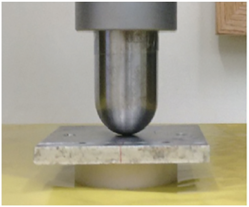
Bone cement sample loading set-up including steel plate and push rod attached to the crosshead of the materials testing machine.
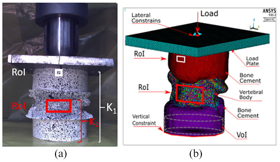
Regions of Interest (RoI) and Volume of Interest (VoI): (a) Vertebral body sample prepared for DIC with the two different RoIs clearly marked. Each RoI allows the loading response of different parts of the specimen to be isolated. The top RoI (white outline) is defined on the superior cement cap, its displacement combined with the applied load will allow an estimate of the stiffness of the whole sample comprising the two cement end caps and VB (
In the case of the cylindrical PMMA specimens, their known geometry allowed to plot stress-strain curves from which Youngs modulus was calculated. Average values for cement stiffness and Youngs modulus for the group were calculated, weighted by the reciprocal of the standard error of the slope of the line of best fit. 23
The loading response of the vertebral sample was further analysed using DIC. Briefly, a single GigE DFK 23GP01 digital camera (The Imaging Source Europe GmbH, Germany) was positioned perpendicularly to the anterior surface of the VB. During compression one image was acquired every 5 s using a custom Matlab code. Ncorr V2.1, 24 a Matlab based open source function, was used to calculate the displacement field on two regions of interest (RoIs) defined on the surface of the superior cement end-cap, close to the point of application of the load, and on the anterior part of the vertebral body, respectively (Figure 2(a)). The average vertical displacement on each RoI was plotted alongside the testing machine load-cell data, thus allowing investigation of the loading response of different portions of the sample; namely displacement data obtained from the superior cement cap RoI allowed to infer the combined stiffness of the whole sample, that is, the combined stiffness arising from the superior cement cap, vertebral body and inferior cement cap (denoted K1, in Figure 2(a)); the vertebral body RoI allowed to estimate the combined stiffness arising from the vertebral body itself and the inferior cement cap (denoted K2 in Figure 2(a)).
Numerical model
The influence of the material properties of the cement end caps on predicted stiffness was studied by means of a specimen-specific FE model of the vertebral sample tested experimentally, Figure 2(b). The geometrical model was created from the previously acquired
Model generation involved software tools such as flood filling, thresholding, painting, filtering and interpolation to create smooth geometries from the
The element types chosen for this study were a mixture of hexahedrons, to represent the internal trabecular structure orientation, and tetrahedrons, to represent and smoothen the external surface9,12,26,27 The geometrical model was converted into FE numerical model and solved using ANSYS Mechanical ADPL (v18.2, ANSYS Inc, USA) installed on a Xeon 32 cores, 120GB RAM PC.
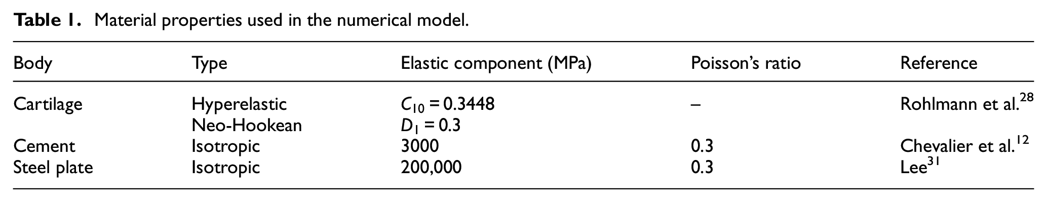
Bone cement, trabecular bone and steel were modelled as isotropic and linear materials while cartilage was assigned as a hyper-elastic material
28
(Table 1). The properties for cartilage and steel were based on literature data; while cancellous bone properties were obtained from the grey-scale of the
Material properties used in the numerical model.
The same load parameters as per the experiment were used in the FE study: a compressive load was applied at a rate of 1000 N/min on the plate up to a maximum of 10 kN. The point of application of the load corresponded to that used during the experiments and it was identified by measuring the distance of the point of contact of the push rod from the edge of the cranial specimen holder. For each VB FE model, three load-displacement curves were generated. The first two were obtained by plotting the reaction loads against the average vertical displacement of element nodes corresponding to the two RoIs used experimentally (Figure 2(b)). Stiffness values
Results
Experimental results
The cement samples stiffness ranged from 112,690 to 176,270
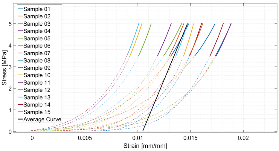
Stress-Strain curves for all samples. The bold sections are the linear sections of the curves and the black line is the weighted averaged curve.
Three load displacement curves were produced for the vertebral body specimen in the experiment. The first and second curve were obtained by plotting the machine load-cell output against the average displacement evaluated by DIC on the top end cap (
Predicted and measured stiffness values.
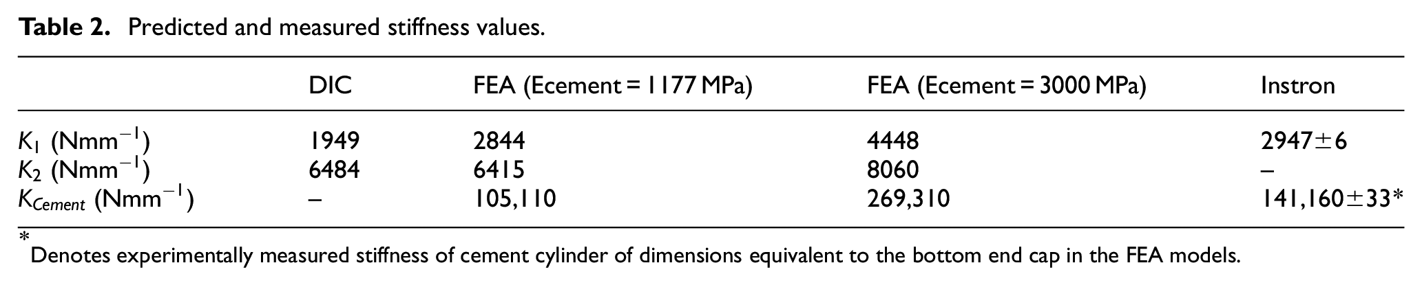
Denotes experimentally measured stiffness of cement cylinder of dimensions equivalent to the bottom end cap in the FEA models.
The load-displacement curve obtained using data from DIC on the RoI defined on the VB resulted in unrealistic specimen behaviour at a load greater than 6 kN (Figure 4). This was due to blood seeping out of the specimen, disrupting the speckle pattern and resulting in the DIC algorithm to output non-physical displacements. Data prior to this load magnitude was unaffected by this issue as confirmed by visual examination of each image.
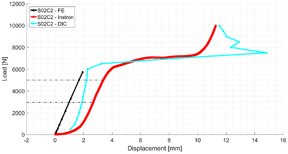
Load-Displacement curves for
Analysis of the
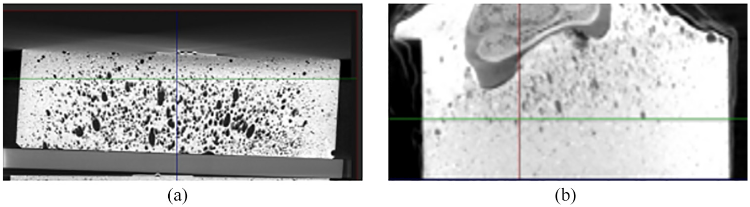
Cross-sectional view of one of the cement samples (a) and cross sectional view of the caudal cement end cap (b).
Numerical results
A mesh sensitivity study was performed to check for convergence of the solution, resulting in a 1 mm element size. This resulted in two models comprising 486,081 elements each, one where cement properties were assigned based on the average value of Youngs modulus obtained experimentally in this study and one with the value obtained from the literature.
Stiffness values were calculated from both models using the reaction forces and the vertical movement of three regions of interest, and resulted in estimates for
Discussion
This study investigated the effect of the material properties assigned to cement end caps on FE models aimed at predicting the response of a vertebral body construct to quasi-static loading. FE is widely used in biomechanical investigations and recent studies have focused on the determination of the right approach to describe the material properties of the biological elements of said models, such as cancellous bone, cartilage, etc32–38; much less attention has been paid to other elements comprising the models, such as cement end caps.
Cement end caps are widely used in experimental spine biomechanics studies3–5; this practice arises from the desire of aligning the vertical axis of vertebral bodies, typically characterised by awkward geometries, to the line of action of the applied force and avoiding point loading. In order to correctly represent the boundary and contact conditions seen experimentally it is common practice to also include cement end caps within FE models.3,4,6–9
Compared to the approach adopted to model biological materials, much less importance has been given to correctly set the material properties of the bone cement, with properties typically being taken directly from the literature.39–42 While adequate when applied to generic models, this approach fails to perform satisfactorily when good agreement with experimental data is sought in specimen-specific FE models. We hypothesised that the generic material properties assigned to bone cement in specimen specific models contribute to the discrepancies between numerical predictions and experimental data.
In this study fifteen bone cement samples, with dimensions comparable to cement end caps, were prepared in the open air and following a standardised mixing protocol 2 ; the same procedure was used to create cement end caps onto which the porcine cervical VB was mounted. Each of the 15 cement samples was subject to a quasi-static loading ramp and the average Youngs modulus for the group was calculated to be 1177 MPa, under half the value commonly reported in the literature and typically used in FEA investigations.1,2,18,31,43
An unusual level and distribution of porosity within the cement was evidenced in the present study (Figure 5). Here cement was mixed by hand, however this practice has been shown not to increase porosity in the solidified material when compared to vacuum-mixing.44,45 We therefore attribute this unusual presentation to the physical size of the samples and the way in which they were produced.
Mechanical tests to determine the properties of bone cement are usually conducted on small cylinder of 5 mm diameter and 12 mm height (ISO 5833:2002), 10 typically produced by pressing doughy cement into open ended cavities created within metal moulds. The metallic material, typically stainless steel, prescribed for mould construction and mould geometry (i.e. with two open ends) decrease the risk of air entrapment during specimen creation. Furthermore, the high thermal conductivity of the mould might contribute to a decrease of the temperature gradient within the sample, reducing the porosity gradient within the cement. On the other hand, bone cement end caps are usually large, with a diameter often in excess of 50 mm6,11–16 and are typically produced within polymer moulds, hence characterised by low thermal conductivity (at least compared to metals), which are sealed at one end to prevent cement leakage. The combination of mould size, its closed geometry and material all result in unfavourable conditions for the cement, with a high likelihood of a temperature gradient arising during polymerisation and air possibly being trapped within the polymer.
Having established an experimental value of Youngs modulus for cement specimens created following the same procedure as the specimen holder end-caps, the next step of the investigation focused on comparing the experimental and predicted response of the vertebral specimen to quasi-static loading. Two specimen specific models were created from the
DIC was used to isolate the experimentally measured stiffness response from different structures within the specimen to match the stiffness regions identified in Figure 2. Average DIC displacements defined on equivalent RoIs (Figure 2(a)) were used to estimate the equivalent stiffnesses to
The use of DIC in the experimental part of this study allowed us to infer the contribution of the cement end caps to the total stiffness of the vertebral sample while affording additional validation steps to the FE models. DIC allowed an experimental estimate of the stiffness of the VB and bottom cement end cap (denoted
The average stiffness of the 15 cement samples was found to be in the order of 141,160 ± 33
DIC allowed to isolate the contribution to overall specimen stiffness arising from different structures within the specimen and, by comparing experimental values to numerical predictions obtained from both models, it was found that the cement end caps accounted for most. However, when cement properties were assigned based on experimental data obtained from samples of equivalent geometry as the end caps and produced with a similar protocol, excellent agreement was obtained between experimental and numerical results.
Conclusion
In this study we have shown that precise setting of the material properties of bone cement will improve the accuracy of the FE stiffness predictions of vertebral samples. Therefore, it is recommended that an in-house characterisation of samples equivalent to the bone cement end cap fixtures is conducted to inform the correct properties to be assigned to this material in the model. Furthermore, we have outlined a technique which allows for robust model validation by exploiting the versatility of DIC measurements.
Footnotes
Acknowledgements
We gratefully acknowledge the support of the Brazilian Government and CAPES for a PhD scholarship (Grant number 99999.001603/2015-09) and FAPESP (Grant number 2014/26366-4) for the initial support.
Authors’ Note
Bruno Agostinho Hernandez, Harinderjit S Gill and Sabina Gheduzzi are also associated with Centre for Therapeutic Innovation, University of Bath, Bath, UK.
Declaration of conflicting interests
The author(s) declared no potential conflicts of interest with respect to the research, authorship, and/or publication of this article.
Funding
The author(s) received no financial support for the research, authorship, and/or publication of this article.