
Abstract
In this study, we present the design considerations of a device to assist in the potential treatment of hemorrhagic stroke with the aim of stopping blood from flowing out into brain tissue. We present and model three designs for the clinical scenarios when saccular aneurysms rupture in the middle cerebral artery in the brain. We evaluate and model these three designs using computer aided design software, SolidWorks, which allows the devices to be tested using finite element analysis and also enables us to justify that the materials chosen were suitable for potential use. Computational fluid dynamics modelling were used to demonstrate and analyse the flow of blood through the artery under conditions of normal and ruptured states. We conclude that our device could potentially be useful in the treatment of hemorrhagic stroke, and the modelling process is useful in assisting in determining the performance of our devices.
Keywords
Introduction
According to the World Health Organization, 15 million people suffer from strokes worldwide per annum and of these 6.2 million people die and 5 million people are left with permanent disability. Stroke is the leading cause of death for people above the age of 60 years and constitutes the fifth leading cause in people aged 15–59 years. In the UK alone, there are more than 100,000 strokes and 38,000 deaths as a result of stroke each year.1,2 Hemorrhagic strokes account for about 15% of all strokes 3 and arises when a blood vessel in or around the brain ruptures.4–7 Weaknesses may occur within the vessels of the brain giving rise to aneurysms. There are several approaches to the treatment of aneurysms7–10 at the pre-rupture stage, which include coiling of the aneurysm. However, if left untreated an aneurysm may rupture resulting in hemorrhagic stroke. There are two types of hemorrhagic strokes: (1) an intracerebral haemorrhage (ICH) and (2) subarachnoid haemorrhage (SAH) (and it is known that hemorrhagic strokes tend to arise more so in hypertensive patients). 11 In hemorrhagic stroke, blood leaks into the brain at high pressure, and causes damage to surrounding tissues and cerebral structures. Escaping free flowing blood not only brings about damage to the brain cells but also causes an increase in intracranial pressure (ICP). This results in a lack of oxygen and nutrients reaching the brain cells. Consequently, the affected cells die. The sudden build of pressure can lead to unconsciousness or death. 12 Therefore, devices are needed to prevent the flow of blood out of the artery/vessel to stop the leakage of blood into brain tissue. Statistics reveal that between 30% and 60% of people who suffer ICH will die.13,14 Of the 25% of people who survive an ICH, some will experience major improvement in their symptoms. However, about 50% will suffer from long-term neurological problems. 15 Other treatments aim to decrease the risk of more bleeding and manage blood pressure so that enough blood will still flow to allow perfusion of the brain. A range of medications may be given that assist in controlling the ICP. These include dexamethasone and mannitol. 16 A major factor in determining the outcome of an ICH rests with controlling the ICP Normal ICP is around 20 mm Hg. Another means of controlling ICP is by removal of cerebrospinal fluid (CSF) from the ventricles. That is facilitated by placing a ventricular catheter (VP shunt) into the ventricles to drain CSF, thus allowing room for the hematoma (that may eventually form) to expand without damaging the brain. 17 Other treatments for larger hematomas situated deep inside the brain include stereotactic aspiration. This procedure involves the attachment of a stereotactic frame with computed tomography (CT) scans to evacuate the blood clot (hematoma). 18 Craniotomy is also used in the treatment of hemorrhagic stroke. This procedure involves cutting a hole in the skull with a drill to expose the brain and removal of the blood. 18
A SAH occurs when a blood vessel ruptures outside the brain and bleeding arises in the subarachnoid space. About 5% of all strokes fall into this category. 12 The subarachnoid space is filled with CSF. Consequently, when blood flows from a ruptured vessel into the subarachnoid space it creates an increase in the volume of fluid in the subarachnoid space. This in turn gives rise to an increase in the pressure inside the skull and over the brain. The increased pressure may then press the brain against the bony skull or cause the brain to shift-a so-called ‘mass effect’ and then herniate. Associated obstruction of the normal CSF flow can bring about enlargement of the ventricles, called hydrocephalus (build-up of fluid in the brain), giving rise to confusion, lethargy and loss of consciousness in the patient.19,20 Vasospasm is also a common complication which may occur 5–10 days after a SAH. This occurs when blood by-products cause irritation of the wall of the artery causing it to contract and spasm. This vasospasm can cause narrowing of the artery lumen which becomes decreased in diameter, which in turn reduces blood flow still further to that area. This can give rise to a secondary stroke. 19 Approximately half of patients who suffer SAH will survive, however many of these will suffer with a disability and the remaining half of cases are fatal. 20
It is clear to see that the main cause of arteries/blood vessels rupture in the brain is due to high blood pressure forming aneurysms. For brain aneurysms treatment surgical clipping is a very common and effective procedure. 21 The aim of clipping is to place a small metallic clip along the neck of the aneurysm. This will prevent blood from entering the aneurysm sac so that it no longer poses a risk of bleeding. In addition, several devices currently in use for treating cerebral aneurysms include coiling methods, flow catheters and biodegradable stents.
There are potential risks involving endovascular coiling, such as injury/damage to the artery or the aneurysm itself and potential rupture of the aneurysm. Furthermore, vasospasm of the artery itself may occur leading to an abrupt narrowing of the artery, resulting in decreased blood flow to the part of the brain being supplied by that artery. A study 22 involving the stent assisted coiling of intracranial aneurysms involved 508 cases. They concluded that stent-assisted coiling of intracranial aneurysms was safe, and effective and gave rise to durable aneurysm closure. However, they further concluded that there appeared to be greater rates of complication when ruptured aneurysms were involved. Long-term success of endovascular coiling to treat aneurysms is about 80%–85%, aneurysm recurrence after coiling occurs in 34% of patients. 23 Recurrence occurs due to coils not completely blocking off the aneurysm or if the coils become compact within the aneurysm. Over 10% of patients will undergo a second treatment to place additional coils, usually within the first year. All patients who have had coiling as treatment for an aneurysm are advised to return after 6, 12 and 24 months for a diagnostic angiogram to monitor for residual or recurring aneurysm. Due to the high cost of coiling and the potential occurrence of recurrence, it is evident that there is a market for a more cost-effective and better performing method for treating ruptured aneurysms in the brain.
Flow diverters can potentially suffer from branch occlusion and aneurysm recurrence. Consequently, these stents are often used for unruptured aneurysms. 24 Bioresorbable polymeric stents 25 are also used. Such biodegradable stents can release substances which include anti-inflammatory drugs to control intimal hyperplasia that can arise on account of the interventional procedure itself. However, such polymeric resorbable stents need to provide adequate strength (together with ease of insertion, etc) for the vessel over a desired period of time.
Aims and objectives
We aim to design and produce a prototype device that could potentially be inserted into a haemorrhaging vessel in the brain. The aim of this device is to ‘plug the gap’ in the ruptured section to stop blood flowing out of the ruptured vessel into the brain causing further damage. To be effective, our device must satisfy a number of requirements; the device must be made of biocompatible material and be quick to deploy in surgery. The device must conform to the ‘Standard ISO-10993’ 26 ‘Biological Evaluation of Medical Devices’; the materials from which it is made must be corrosion resistant; the device must also ideally be visible on X-ray visualisation and radiographic filming techniques such as computed tomography angiography (CTA) scan, for the surgeon to view the deployment of the device during and after surgery; the device must be effective in stopping the bleeding in the artery, capable of remaining in situ post deployment, and able to stay in the brain for the duration of the patient’s lifetime; the device must not impede the natural flow of blood through the artery; the device must fit individual vessels; the device must also withstand the effects of vasospasm; the design must be ‘leak-proof’ and not allow blood to seep through out of the aneurysm rupture and into the brain.
From the Design Specifications, we have come up with a few suitable designs of self-expanding Nitinol stent with expanded polytetrafluoroethylene (ePTFE) graft, and the following studies illustrate the modelling of the devices and their expected mechanical performance while being implemented.
The designs were undertaken using SolidWorks, using the feature ‘sheet metal’. All designs were 8 mm in length and 3 mm in diameter with wall thickness 0.2 mm.
Computer-aided design modelling
The steps in the design are shown in Figure 1(a)–(f). A hollow tube with an inner diameter of 2.6 mm, outer diameter of 3 mm and 8 mm height was modelled. The tube was then cut two-thirds along its length. A ‘sheet metal’ was created from the remaining one-third tube and flattened using the ‘flatten-bends’ tool (Figure 1(c)). Once the flat sheet was obtained, the geometry of the stent could be created as a pattern (step 3). The flat sheet was then curved back into the one-third tubing. Finally, from the one-third part assembly the three separate parts were then joined together to form the full stent.
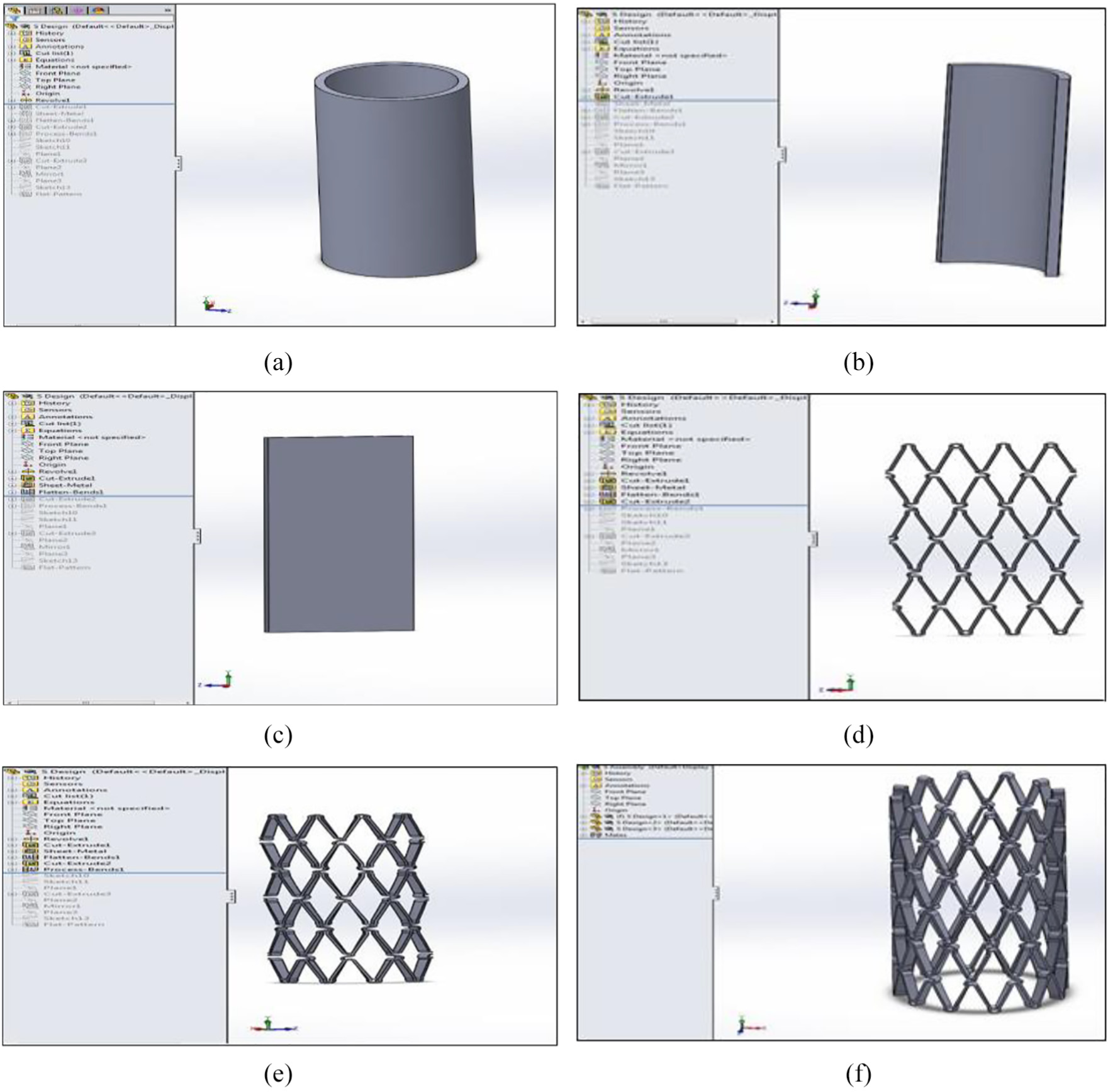
Sheet metal: (a) step 1, (b) step 2, (c) step 3, (d) step 4, (e) step 5 and (f) sheet metal-finished assembly, step 6.
Our three designs are shown in Figures 2–4.
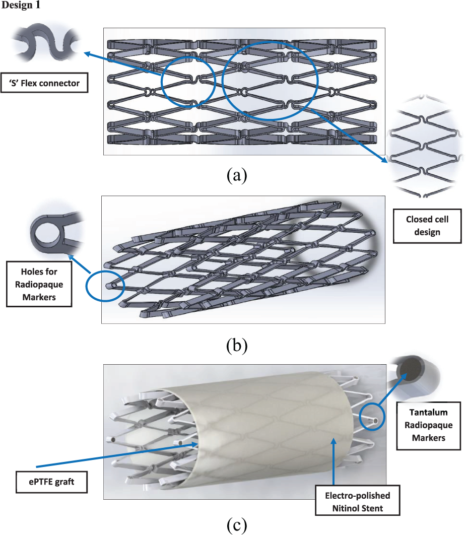
Design 1: (a) side view, (b) angle view and (c) stent and graft material.
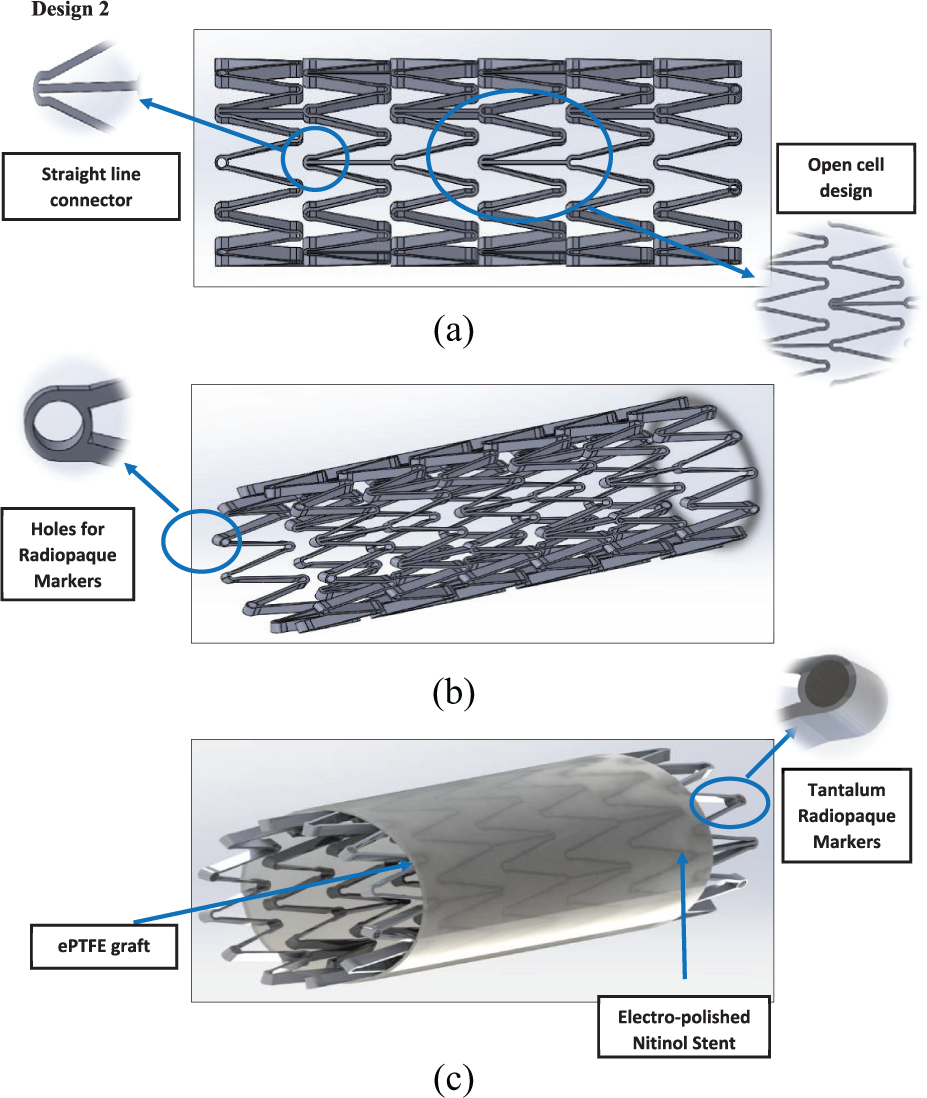
Design 2: (a) side view, (b) angle view and (c) stent and graft material.
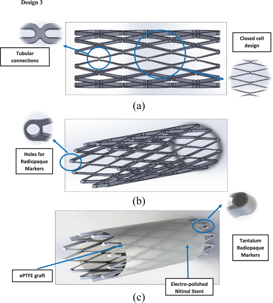
Design 3: (a) side view, (b) angle view and (c) stent and graft material.
The main features of the design are tabulated in Table 1.
Overview of the designs.
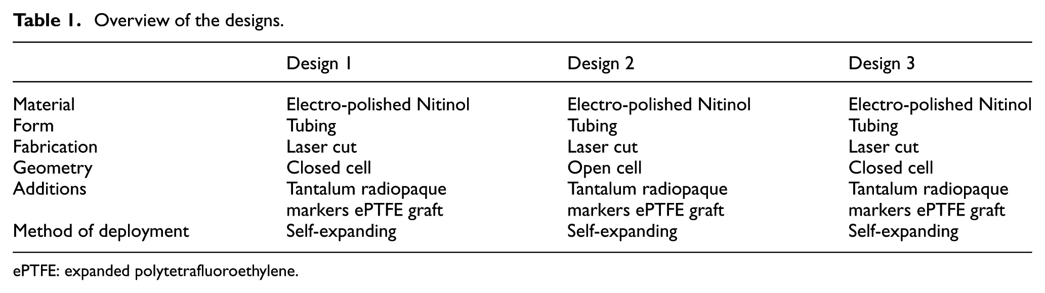
ePTFE: expanded polytetrafluoroethylene.
A key feature of the design concerns how to attach the ePTFE graft to the Nitinol stent. The material chosen was ultra-high molecular weighted braided polyethylene (UHMWPE). It was chosen due to its strength, durability, its properties involving knot tying and polyester core which was designed to enhance knot security.27,28 Another feature that the stent device might have is anchoring pins (Figure 5). Anchoring pins are used to anchor the stent into the artery wall, so the flow of blood does not dislodge the anchoring pins, or if any vasospasm occurs, the device will not be dislodged from its position. The anchoring pin will anchor itself into the tunica intima of the artery wall.
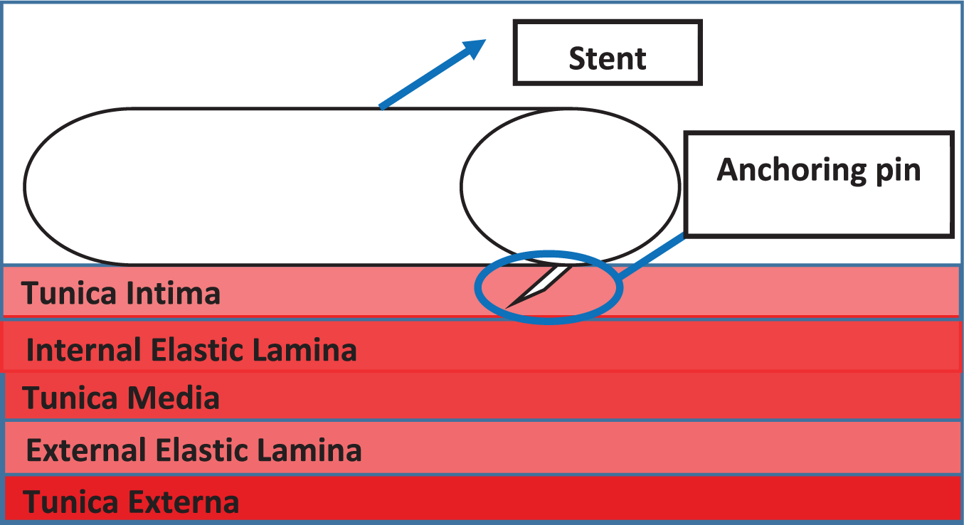
Schematic view of the anchoring pin.
Design calculations and finite element analysis modelling
Clearly the choice of materials to be used is very important29–31 to demonstrate that the chosen materials (Nitinol and ePTFE) for the device could withstand the forces/pressures exerted on them after deployment. In the artery, the minimum thickness of the stent and ePTFE graft was calculated. This calculation together with the hemodynamic calculations are shown in Appendix 1. Blood travelling through arteries/blood vessels exerts a hoop stress against the vessel’s walls. This same force would therefore be exerted against the device inserted into a ruptured blood vessel. These equations were used to determine the parameters related to haemodynamic flow and forces: since failure would occur when the hoop stress exceeded the ultimate tensile strength (UTS) of the material, the UTS was used instead of the hoop stress to calculate the minimum thickness needed. The results are summarised in Table 2.
Minimum thicknesses of stent and graft material.
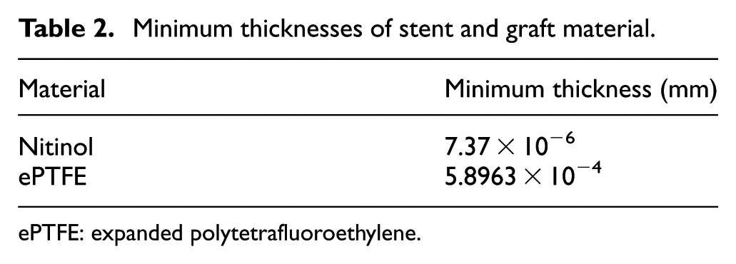
ePTFE: expanded polytetrafluoroethylene.
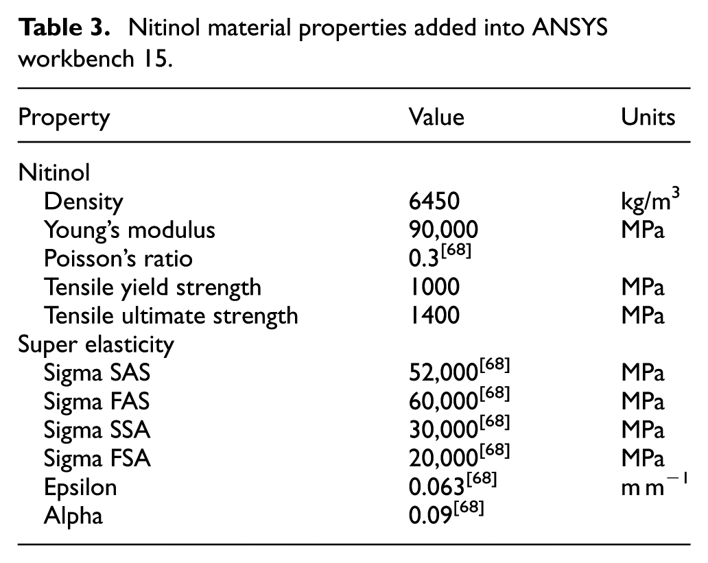
A value of 0.2 mm was chosen for the stent thickness and the ePTFE graft thickness was chosen to be 0.0508 mm taking into account a safety factor; ePTFE graft diameter: 3.0508 mm; stent diameter: 3 mm. To evaluate the stent design, ANSYS workbench 15 was used for finite element analysis (FEA) together with computational fluid dynamics (CFD). The testing involved validating the design and to see if the materials chosen could withstand the conditions inside an artery and the behaviour of the material. Since ANSYS workbench 15 32 did not have the materials Nitinol and ePTFE in its database, these were added into the database manually using the material properties from Tables 3 and 4. In the FEA, the pressure being applied to the structure and graft material was the mean arterial pressure during hypertensive crisis as this would mimic the conditions in which the stent would be facing after deployment. The mean arterial pressure was doubled from 133 to 266 mm Hg when testing to prove the device could withstand even the worst-case scenario.
Nitinol material properties added into ANSYS workbench 15.
ePTFE material properties added into ANSYS workbench 15.
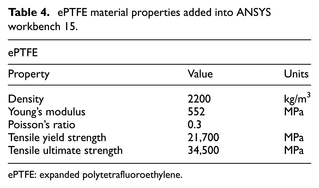
ePTFE: expanded polytetrafluoroethylene.
Our FEA designs are shown in Figures 6–8.
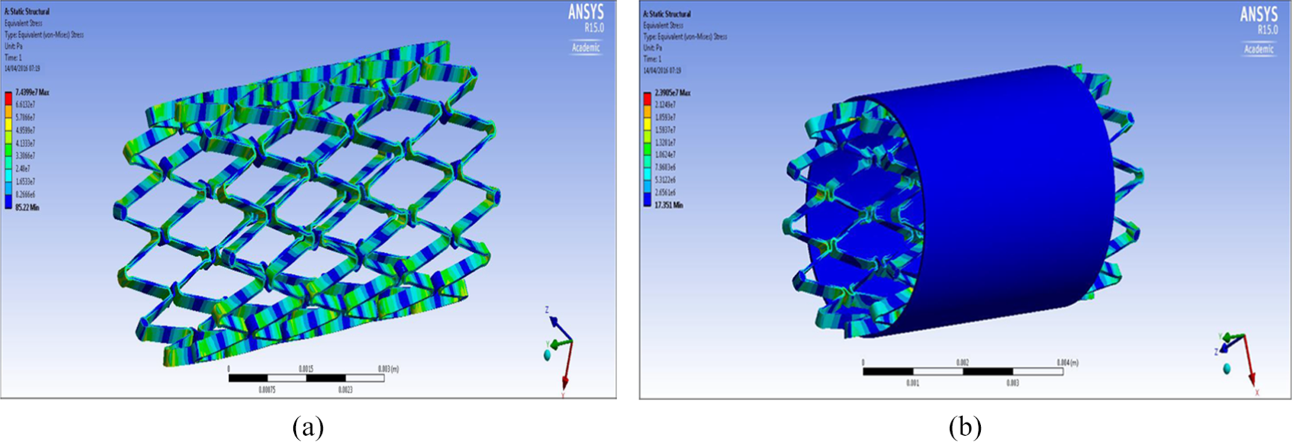
FEA design 1 stent: (a) structural analysis and (b) graft analysis.
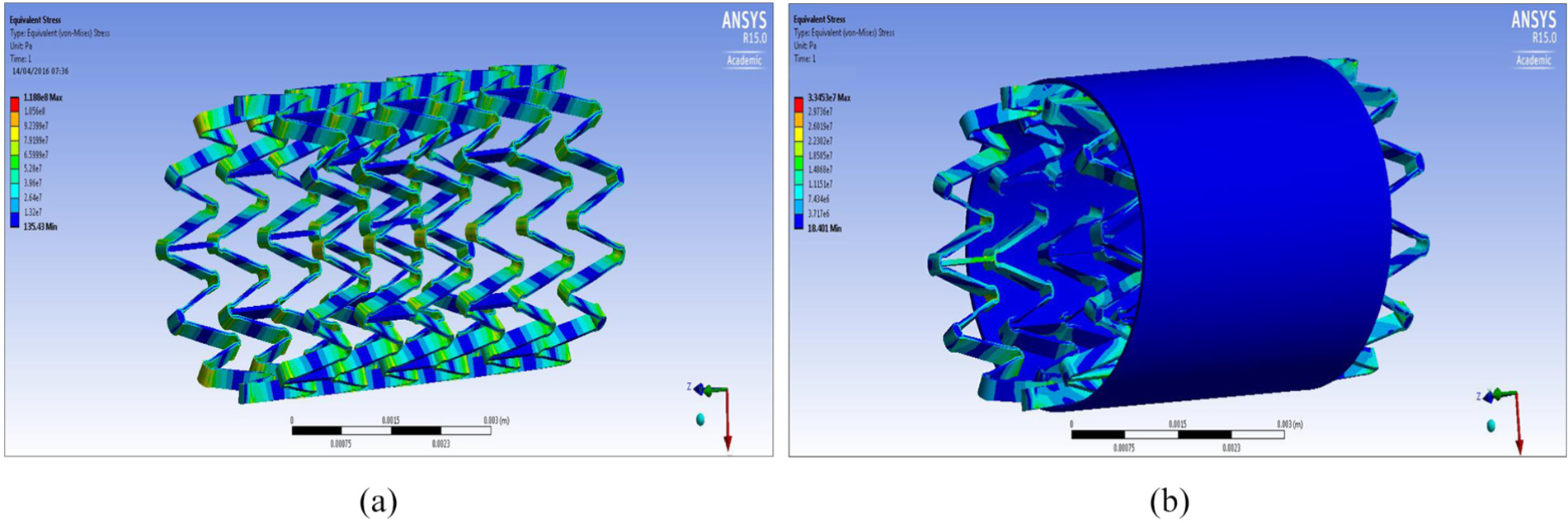
FEA design 2 stent: (a) structural analysis and (b) graft analysis.
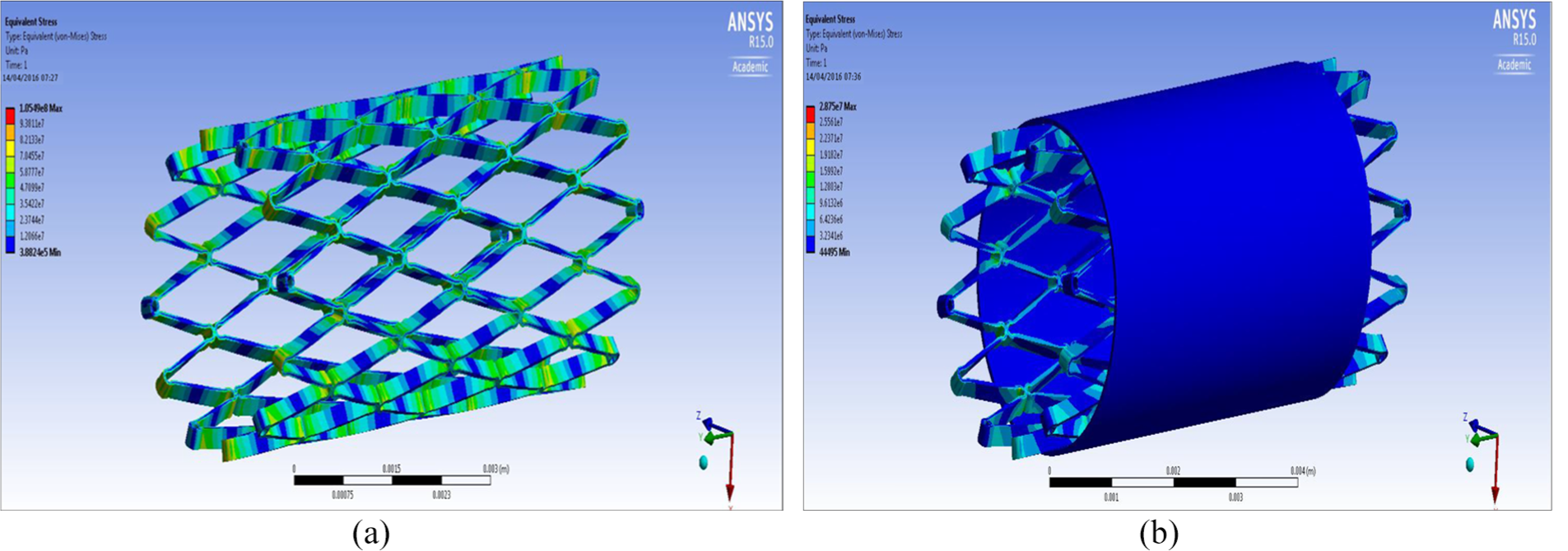
FEA design 3 stent: (a) structural analysis and (b) graft analysis.
FEA results overview
Table 5 shows an overview of the results of the FEA, the Von Mises stress of all the designs were compared against the yield strength of Nitinol and ePTFE: yield strength (Nitinol) – 1000 MPa; yield strength (ePTFE) – 21,700 MPa.
FEA results overview.
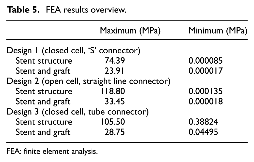
FEA: finite element analysis.
It can be seen from the FEA testing (Table 5) that design 1 (closed cell, ‘S’ connector) performed the best and design 2 (open cell, straight line connector) performed the worst of the three designs. Taking into account the yield strength of Nitinol and ePTFE it can be seen that designs 1 and 3 were under a tenth of the yield strength of Nitinol while design 2 was just over a tenth. When the ePTFE graft was added for the analysis, the Von Mises stress of all three designs dropped significantly and were now 3.4% of the yield strength of Nitinol and 0.15% of the yield strength of ePTFE (Table 6). This analysis showed that changes could be made to the thickness of the stent structure and ePTFE graft material, that is, that they both could be decreased, which would save a substantial amount of cost during the manufacturing process.
Summary of FEA results.
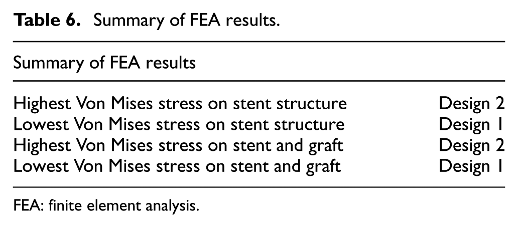
FEA: finite element analysis.
CFD analysis
To perform CFD analysis, consideration was given to the fact that blood is a non-Newtonian fluid with pulsatile flow. The equations used were the continuity and Navier-stokes equations.
Continuity equation
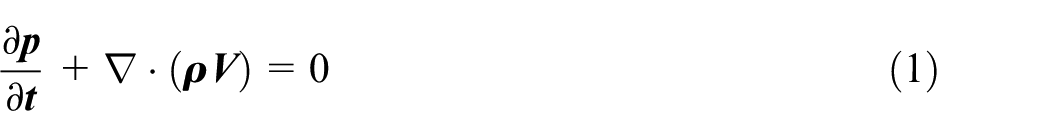
However, as blood can be regarded as an incompressible fluid, the rate of density change is zero, thus the continuity equation can be simplified to the following form

Navier–Stokes equation
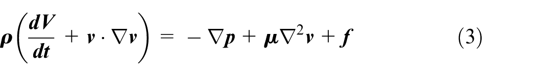
The viscosity coefficient of
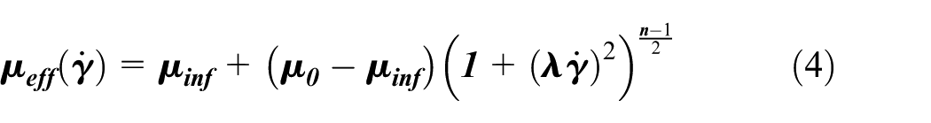
where
Boundary conditions
Inlet
Mammalian blood flow is both pulsatile and cyclic in nature, hence the velocity at the inlet will not be a constant but instead has a time varying periodic profile. The pulsatile profile within each period is considered to be a combination of two phases, systolic and diastolic. This pulsatile profile is shown in Figure 9. During the systolic phase, the velocity inlet varies in a sinusoidal pattern, the sine wave during the systolic phase has a peak velocity of 0.5 m/s and a minimum velocity of 0.1 m/s. So, if we assume a heartbeat rate of 120/min, the duration of each period will be 0.5 s. This is the time analysed for the transient flow.
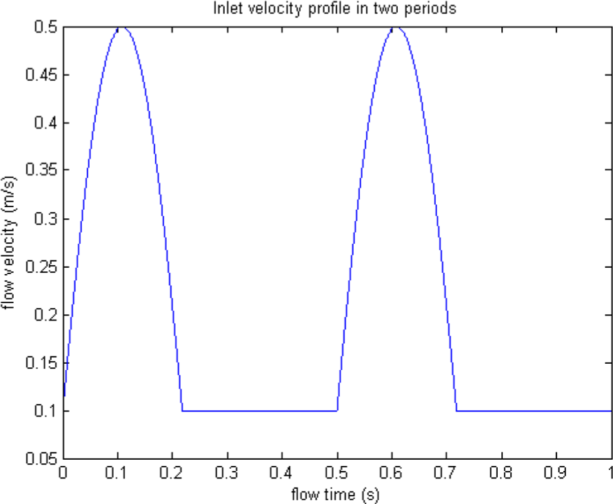
The blood flow pulsatile profile.
Outlet
The outlet was set using the mean arterial pressure of someone in a hypertensive crisis which is 133.3 mm Hg. However, for the purpose of our analysis, a higher value of 180 mm Hg was used which equated to 23,994 Pa. The CFD analysis undertaken aimed to show how blood flows through (1) a ‘normal middle cerebral artery’, (2) ‘middle cerebral artery with a fusiform aneurysm’ and (3) ‘middle cerebral artery with a saccular aneurysm’ and with the latter two, ruptures of aneurysms in these arteries, respectively.
Middle cerebral artery‘no aneurysm’ simulation
The ‘no aneurysm’ condition (i.e. normal artery) was first considered in order to show the analysis undertaken would match what theoretically happens in a normal blood vessel, theory states that ‘blood flow velocity is faster in the middle of the artery and slowest at the vessel wall’. 34
Figure 10(b) and (c) demonstrates that the velocity of blood flow is faster in the centre of the artery as the velocity is 1.85e−1 compared to at the walls where it is 4.62e−2. These figures show that the inlet pressure is 24,030 which is higher than outlet pressure which was set at the boundary conditions, this shows the pressure of flow entering the middle cerebral artery (MCA) is lower than what is leaving.
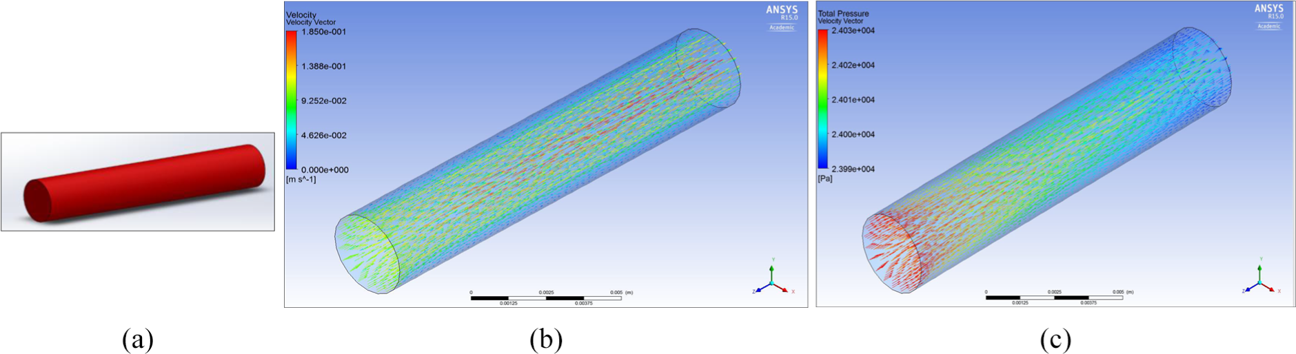
(a) Middle cerebral artery, (b) velocity through MCA no aneurysm and (c) total pressure through the MCA no aneurysm.
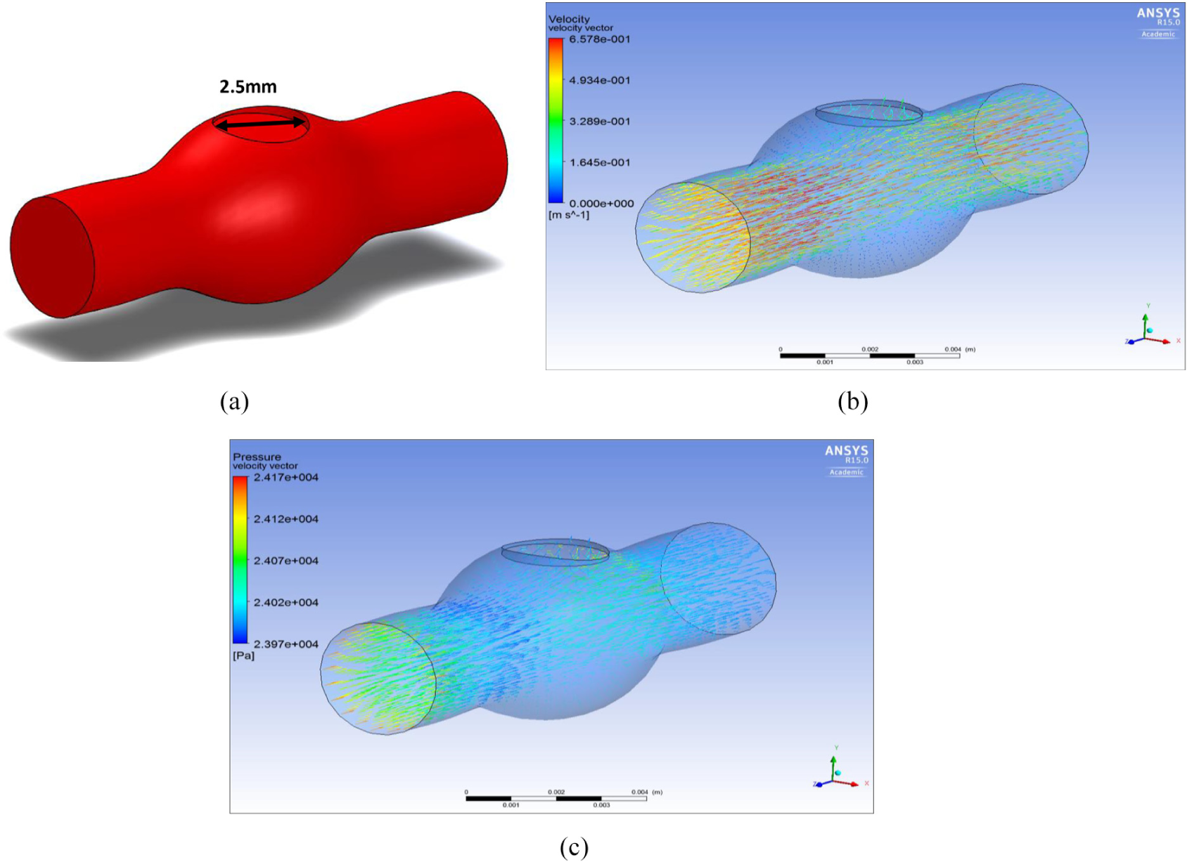
MCA fusiform aneurysm
Figure 11(b) shows how the flow disperses into the fusiform aneurysm and no longer stays linear as it would in a normal MCA.
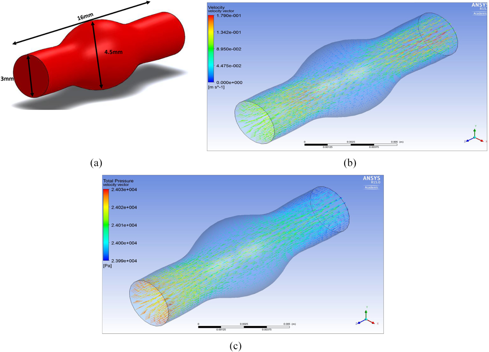
(a) MCA fusiform aneurysm, (b) velocity through MCA fusiform aneurysm and (c) total pressure through MCA fusiform aneurysm.
Figure 11(c) shows the total pressure through a MCA fusiform aneurysm, it can be seen that as the blood travels through the artery and flows against the walls of the fusiform aneurysm the pressure is higher than the outlet.
MCA fusiform ruptured
Figure 12(b) shows a rupture in the fusiform aneurysm, it can be seen that due to the rupture the flow velocity dramatically decreases and some of the flow, flows out of the artery. This flow leaving the artery is the blood which will go into the brain and cause damage/complications as discussed earlier in the background research. Figure 12(c) shows the total pressure through a MCA fusiform ruptured.
(a) MCA fusiform ruptured, (b) velocity through MCA fusiform ruptured and (c) pressure through MCA fusiform ruptured.
MCA saccular aneurysm
Figure 13(b) shows the velocity of flow through the MCA saccular aneurysm and it can be seen during a saccular aneurysm that the flow increases as it leaves the MCA.
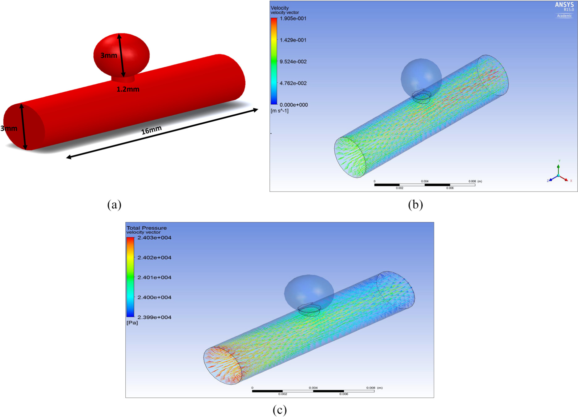
(a) MCA saccular aneurysm, (b) velocity through MCA saccular aneurysm and (c) pressure through MCA saccular aneurysm.
Figure 13(c) shows the pressure through a MCA saccular aneurysm and it can be seen that there is a pressure of 2.401e 4 Pa going into the saccular aneurysm.
MCA saccular aneurysm ruptured simulation
Since 80%–90% of all aneurysms are of the saccular type, we used CFD analysis undertaken aimed to show how blood flows through middle cerebral artery saccular aneurysm ruptured. The inlet boundary was set as a velocity-inlet and the rupture and outlet boundary were set as pressure-outlet.
Figure 14(b) shows the velocity through an MCA saccular aneurysm ruptured. It can be seen that as the flow reaches the ‘sac’ of the aneurysm which is at the base of the aneurysm, the velocity increases quite significantly and flows out. The blood consequently leaves the aneurysm and passes into the brain where it can cause damage/complications to brain tissue.
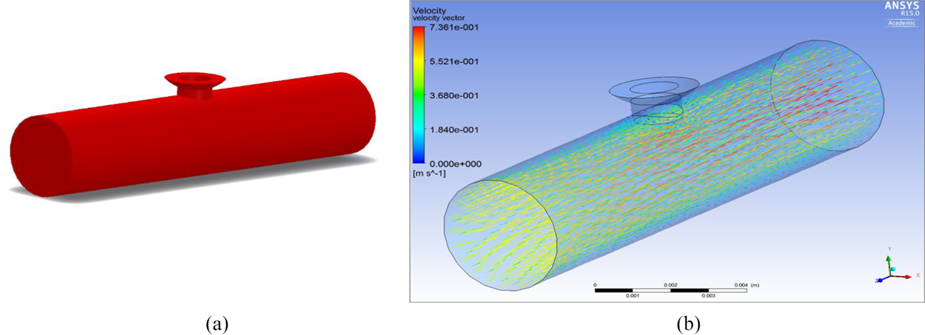
(a) Saccular aneurysm ruptured and (b) velocity through MCA ruptured saccular aneurysm.
MCA saccular aneurysm ruptured with device simulation
CFD analysis has been used to show how design 1 (design which performed the best during FEA) would stop blood flow from a ruptured saccular aneurysm since it is the most common type. The inlet boundary was set as a velocity-inlet and the rupture and outlet boundary were set as pressure-outlet.
Figure 15(a) shows the ePTFE graft in a ruptured aneurysm. It can be clearly seen that with the inserted graft material the flow is blocked from going into the rupture and into the brain. This analysis is central to showing that the proposed device can function for its intended purpose.
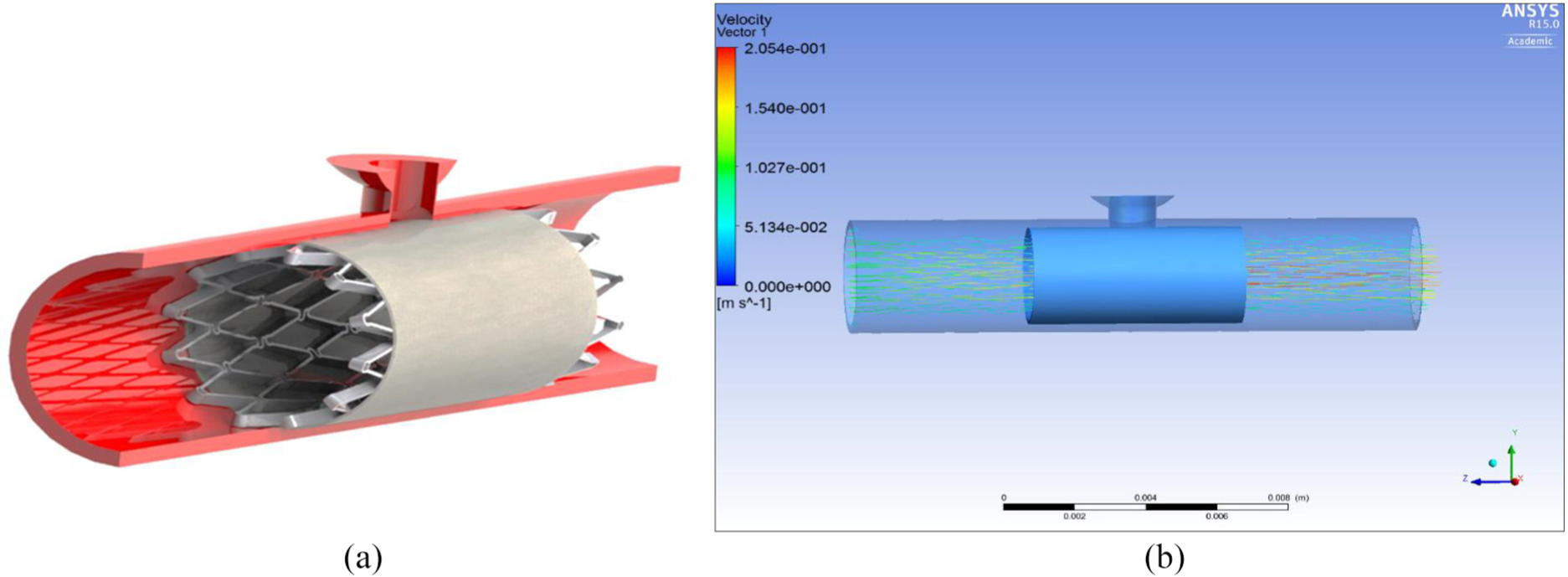
(a) Design 1 in situ in a ruptured MCA saccular aneurysm and (b) velocity through graft material of the ruptured MCA saccular aneurysm.
Discussion and conclusion
In our study, we investigated three designs for use in arteries in the brain that are commonly involved in haemorrhagic strokes, for example, the MCA. We presented the results of modelling the capacity of these devices to prevent blood flowing out from the arterial rupture of saccular aneurysms. FEA was carried out on all three designs which validated that the materials chosen for the devices were fit for purpose and would not fail under the worst case scenario (double of the mean arterial pressure during hypertensive crisis). CFD testing was carried out to see what the different type of flow was like in a normal middle cerebral artery (MCA), MCA with a fusiform aneurysm, MCA with a saccular aneurysm and when a saccular aneurysm ruptured. Then after rupture of a saccular aneurysm the device was shown to stop the flow from leaving the MCA at the rupture, effectively ‘plugging the gap’.
An ePTFE graft appeared to be successful blocking blood flow out of an artery in a ruptured aneurysm. It would appear therefore that at least in principle this type of material would potentially be useful in arresting the flow of blood out of a ruptured artery in haemorrhagic stroke. However, we note that further research would need to be undertaken to investigate the biocompatibility issues associated with the ultimate choice of material.
Such modelling enables us to predict the performance of the devices without having to build several prototypes, thus enabling a given device to be optimised prior to prototype manufacture taking place, this saving on costs.
For the new device to be successful it has to meet vital requirements: be easily inserted into the blood vessel/artery; deployed quickly and efficiently to minimise blood loss into the brain; bio-compatible so it won’t be rejected by the patient; excellent mechanical properties to stop it failing under the pressure of blood flow. The proposed self-expanding stent can potentially satisfy these requirements. Comparing to balloon-expanding (BX) method, self-expanding (SX) stents can be more suited for the device. The main reasons are that they can adapt their shape to the vessel wall, become a part of the anatomy and act in harmony with native vessels and support the vessel wall. Radial compliance of an SX stented vessel is much greater than that of a typical BX stented vessel. Axial stiffness, which is directly reflected in bending compliance, is also different, with SX stents being again much more compliant than BX stents of identical design; this applies both in delivery and deployment. Self-expanding stents have no strength limitation and elastically recover even after complete flattening or radial crushing. Which makes them the ideal choose for when vasospasm occurs as they won’t resist the narrowing and increase the size of rupture/damage to the artery.
Nitinol material’s super elasticity was best suited since Nitinol alloys are the only stent material which follows the same elastic deformation behaviour of the structural materials of the living body. 35 ePTFE was chosen due to its superior density and elongation values. These materials will facilitate the deployment of the stent.
Hooks are commonly used in arterial stents. It is important however to consider blood flow velocity and blood pressure in particular artery in the brain at specific anatomical site. This would be the subject of further investigation in abattoir and cadaveric specimens with practical flow dynamics added including radial forces in intracranial arteries in conjunction with a range of anatomical variants. This would yield information on whether use of a hook would be an asset.
Out of the three designs proposed, the FEA modelling results indicate that device number 1 had the best performance. As the device has been modelled on SolidWorks, the next step would involve the manufacturing of a prototype device, so that testing procedures can be carried out to validate its performance in respect to factors such as longitudinal compression, radial compression, 3-point bending, and torsion. Based on such measurements, the performance of the device can then be fine-tuned and optimised for potential use in haemorrhagic stroke treatment. Such CFD modelling is useful in predicting the performance of the device under given conditions in particular vessels in the brain, for example, the results in Figure 15 of modelling an ePTFE graft indicated the successful blocking of blood flow in a ruptured aneurysm. Our results also showed that choice of material, thickness and elasticity are important factors in the design process and that these also should be biocompatible. Although we recognise that computational modelling has limitations and is no ultimate substitute for physical testing, nevertheless the type of modelling we have undertaken is a useful adjunct in the design and testing of the performance of such devices.
Footnotes
Appendix 1
Declaration of conflicting interests
The author(s) declared no potential conflicts of interest with respect to the research, authorship and/or publication of this article.
Funding
The author(s) received no financial support for the research, authorship and/or publication of this article.