
Abstract
The current study was designed to investigate the mechanical response of a polyetheretherketone-on-polyethylene total knee replacement device during a deep squat. Application of this high-demand loading condition can identify weaknesses of the polyetheretherketone relative to cobalt-chromium. This study investigated whether the implant is strong enough for this type of loading, whether cement stresses are considerably changed and whether a polyetheretherketone femoral component is likely to lead to reduced periprosthetic bone loss as compared to a cobalt-chromium component. A finite element model of a total knee arthroplasty subjected to a deep squat loading condition, which was previously published, was adapted with an alternative total knee arthroplasty design made of either polyetheretherketone or cobalt-chromium. The maximum tensile and compressive stresses within the implant and cement mantle were analysed against their yield and fatigue stress levels. The amount of stress shielding within the bone was compared between the polyetheretherketone and cobalt-chromium cases. Relative to its material strength, tensile peak stresses were higher in the cobalt-chromium implant; compressive peak stresses were higher in the polyetheretherketone implant. The stress patterns differed substantially between polyetheretherketone and cobalt-chromium. The tensile stresses in the cement mantle supporting the polyetheretherketone implant were up to 33% lower than with the cobalt-chromium component, but twice as high for compression. Stress shielding was reduced to a median of 1% for the polyetheretherketone implant versus 56% for the cobalt-chromium implant. Both the polyetheretherketone implant and the underlying cement mantle should be able to cope with the stress levels present during a deep squat. Relative to the cobalt-chromium component, stress shielding of the periprosthetic femur was substantially less with a polyetheretherketone femoral component.
Keywords
Introduction
Over the last few years, efforts have been made to study the potential of an all-polymer total joint replacement.1–7 In the area of total knee arthroplasty (TKA), these efforts started with carbon fibre–reinforced (CFR) polyetheretherketone (PEEK) on ultra-high molecular weight polyethylene (UHMWPE) and were aimed at understanding the wear of this bearing couple. Research revealed that CFR-PEEK was not a suitable mating surface for UHMWPE in TKA. 3 Non-CFR (virgin) PEEK seems to have overcome these problems, paving the way for further mechanical studies.3,6,7
The present study adds to the mechanical understanding of a PEEK femoral TKA implant by focussing on the mechanical integrity of the reconstruction. PEEK is inherently weaker than conventional cobalt-chromium (CoCr) alloys and is also much more compliant (3.7 GPa vs 210 GPa). The differences in material properties may entail potential risks with regard to the integrity of the implant and underlying cement mantle. On the other hand, the more compliant PEEK could also promote more physiological loading of the periprosthetic bone,6,8–10 thereby reducing stress shielding observed in CoCr components in TKA.11–16 Rankin et al. 6 demonstrated in an experimental study with digital image correlation techniques that a PEEK femoral component generates more physiological surface strains than a CoCr implant in a synthetic bone under stance phase loading conditions. In the present finite element (FE) study, we are able to get a more holistic perspective of the effects of a PEEK component on the stresses and strains within the bone and implanted materials.
Previously, we used finite element analysis to evaluate the biomechanical behaviour of a PEEK implant during level gait. 17 That study showed that it is unlikely that a PEEK implant would fail under relatively low burden circumstances. In the current study, we aim to evaluate the PEEK implant design under high-demand activities. A deep squat represents one of the more demanding loading scenarios for a TKA device, as both the tibiofemoral and patellofemoral loads are substantial, which may have consequences for the mechanical integrity of the reconstruction.
In the present study, we addressed the following questions regarding a deep squat: (1) Is a PEEK femoral implant strong enough to endure high-demand loading? (2) Are stresses in the cement mantle elevated with a PEEK implant? (3) Does a PEEK femoral component have potential to reduce periprosthetic bone remodelling after TKA?
Materials and methods
To perform a biomechanical study of the knee reconstruction, a finite element model (MARC2012; MSC Software Corporation, Santa Ana, CA, USA) of a TKA component (Maxx Freedom Knee) subjected to a deep squatting loading mode, which was earlier reported, 18 was adjusted and used. This was a two-stage model in which the kinetics and kinematics were determined in a ‘global’ model, while the analyses of structural integrity and local load transfer were performed in a ‘local’ model. This method improves computational efficiency and reliability, yet retains the ability to capture deformation of the implant and femoral bone in the local model.
The global model
The global model consisted of a femoral implant, tibial implant and cement layer, proximal tibia, fibula, patella, small sections of the epiphyseal femur, the posterior cruciate ligament (PCL), patella tendon and the quadriceps tendon. The model was fixed at the proximal end of the quadriceps tendon and the backside of the femoral component (Figure 1). Distally, the model was attached with springs to a node representing the ankle joint. This node transferred a constant ground reaction force from the ankle to the model. Motion in the model was then enabled by gradually releasing (elongating) the quadriceps tendon in each increment, mimicking the eccentric contraction of the quadriceps muscles, in a controlled squat from 40° to 150° of flexion. The model could further move unconstrained (6 degrees of freedom) to find a knee joint equilibrium.
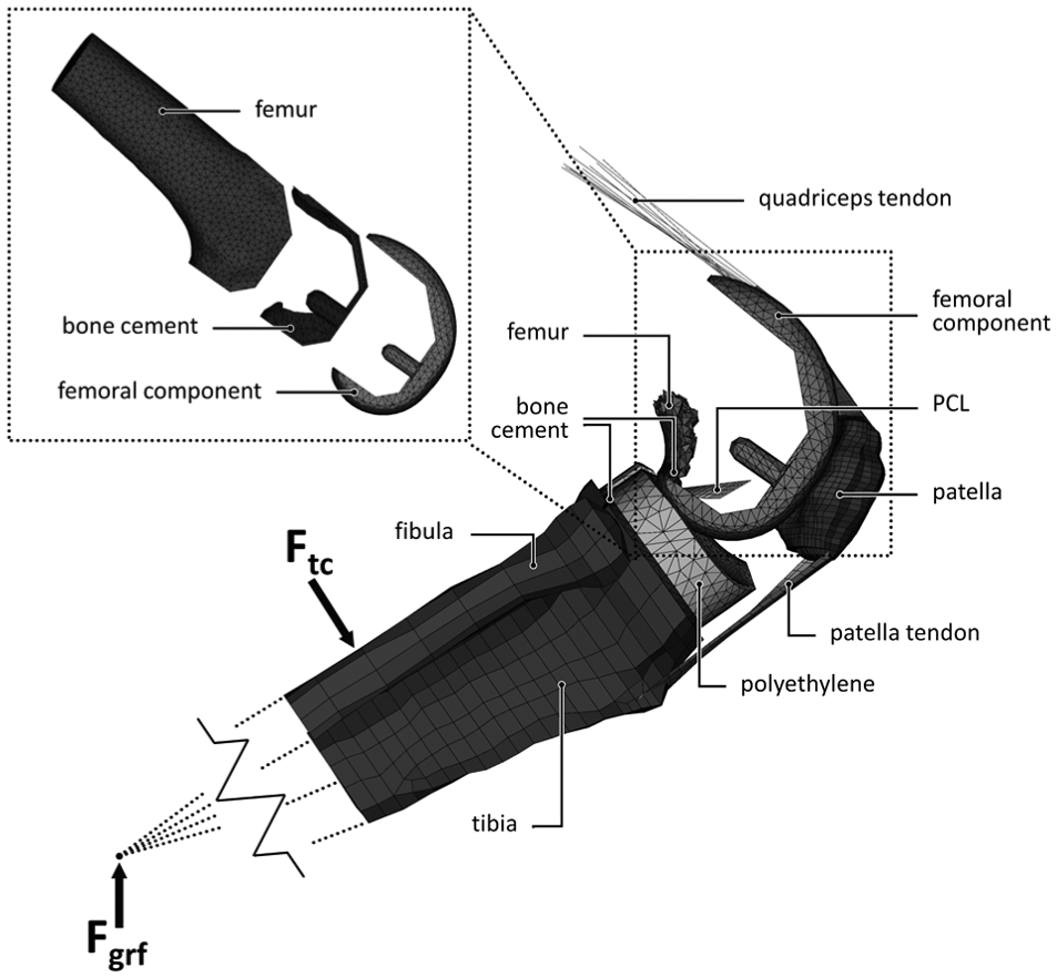
The global and local (top left) finite element model and its components.
The former model 18 included a high-flex implant design with extended condylar curvature. However, in the current study, the implant did not have these extended features which is why we introduced the possibility of load sharing between the tibial component and posterior distal femoral bone as this is known to reduce the loads on the implant in vivo. 19 Also thigh–calf contact was included, which has been shown to affect the intra-knee loading conditions. 20 Zero friction contact between the femoral and tibial component was modelled, as friction was shown to play a negligible role in a high-demand loading scenario. 18 The tibiofemoral, patellofemoral and tendon contact forces that were exerted on the femoral component bearing surface during the squat were incrementally stored and later applied to three versions (intact knee, CoCr component, PEEK component) of the ‘local’ model under the assumption that femoral contact surface material stiffness does not affect the squatting kinetics and kinematics.
The local model
The local model consisted of the distal half of the femur, a cement mantle and femoral implant with the same mesh as present in the global model (Figure 1). Both the geometry and the stiffness of the distal femur were obtained from a CT scan of an 81-year-old male with no known history of bone disease. The local bone density was linearly scaled, converted to Young’s moduli in a physiological range,21–23 and assigned to the bone elements.
Fully bonded conditions were assumed at the cement–bone and cement–implant interfaces. The proximal 3 cm of the femur was constrained for all degrees of freedom and the forces calculated from the global model were applied to corresponding locations on the local model at each increment of the squat cycle.
Material properties
Because of the preclinical nature of this research, clinical data were not available for external validation of the PEEK model. Considering the extensive experience with CoCr TKA devices and their clinical success, the CoCr reconstruction was used as a benchmark for the PEEK model and comprised the same geometry. The impact of either PEEK or CoCr on the bone stresses and strains was assessed by the comparison to a model of the intact femur. To that end, three versions of the model were adopted (intact, CoCr and PEEK), differing in material properties, obtained from either the manufacturer or the literature (Table 1).18,21–25 The ‘intact’ model did not differ in geometry from the PEEK and CoCr, but rather used CT bone densities throughout the entire distal femur. Elements overlapping with cartilage tissue or joint space would thus receive an analogue stiffness. Using the same mesh rather than creating a separate model of the intact femur ensured a clean comparison, without artefacts following from differences in the meshes.
Material properties.
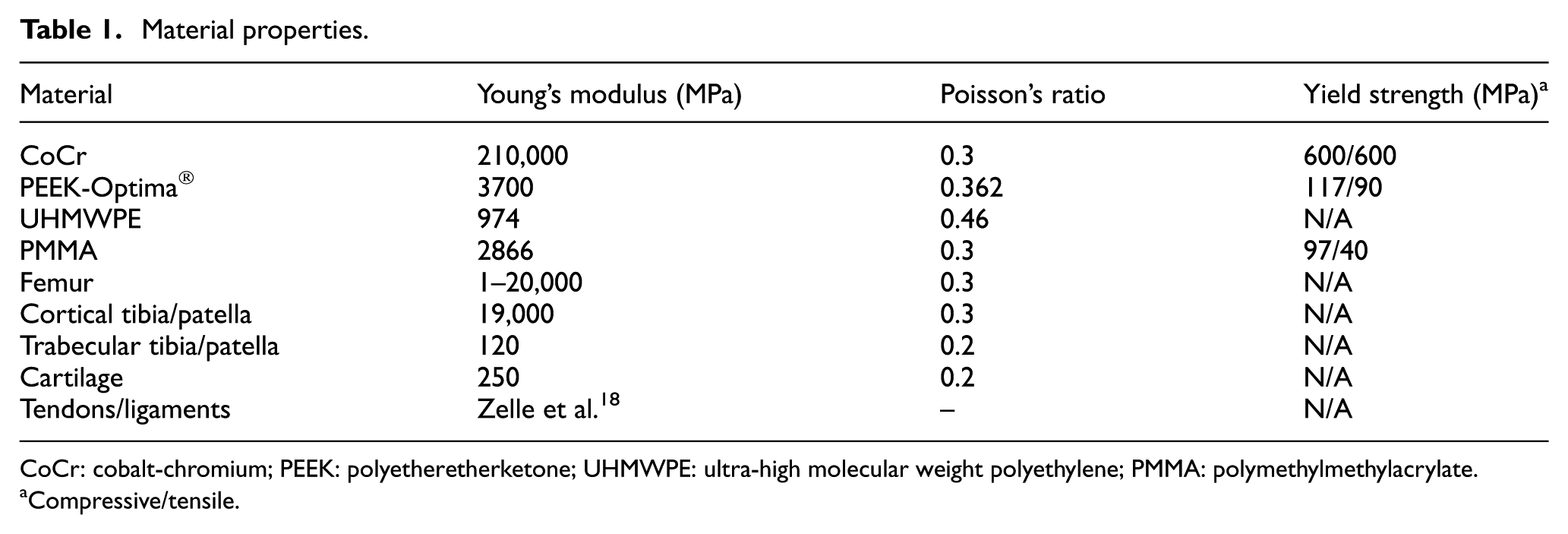
CoCr: cobalt-chromium; PEEK: polyetheretherketone; UHMWPE: ultra-high molecular weight polyethylene; PMMA: polymethylmethylacrylate.
Compressive/tensile.
Data analysis
For both the femoral component and cement mantle, the minimal (compressive) and maximal (tensile) principal stresses were analysed with respect to the yield stress of either PEEK or CoCr (Table 1). Besides contour plots of stresses on the geometry, also the fraction of the mesh volume exposed to certain stress levels are presented. For tensile analyses, the mesh volume fraction that exceeded the 1 million cycle tensile fatigue stress was used to identify areas that may be at risk. For CoCr and PEEK, the 1 million cycle tensile fatigue stress was about 70% of tensile yield stress,26,27 and for PMMA, it was 40%. 28 Fatigue failure as a result of compression is not plausible and was therefore omitted in the current study.29,30
Periprosthetic ‘stress shielding’ was quantified by strain energy density (SED) as this is regarded as the stimulus for bone remodelling.31,32 From the SED data obtained in the volume of the periprosthetic bone, a simulated sagittal DEXA reconstruction was made for qualitative comparison with published clinical and FE studies (Figure 6). The local reduction of the SED in each TKA reconstruction was quantified by a percentage of the original (intact) stimulus. Since the SED was assumed not to be normally distributed, results were described with the median and interquartile range (IQR).
Throughout the deep squat, data were recorded to obtain a stress distribution to allow for a quick overview of the effect of flexion angle on the mechanical outcome parameters. The flexion angle was determined as the sagittal angle measured between the node for ground reaction force application (moving), the centre of the intercondylar space (fixed) and a node representing the hip joint (fixed). Further analyses were performed at 90° (a common angle in more frequent tasks such as sitting down), 120° of flexion (a relevant maximum post-operative flexion angle clinically observed33–35) and 145° of flexion where maximum stresses were found in the implant (Figure 2). Although the model was able to achieve a 155° flexion angle, above 145° thigh–calf contact and femoral load sharing substantially reduced the loads on the knee. To avoid inclusion of stress peaks resulting from mesh artefacts, the 99th percentile of the stresses is presented.
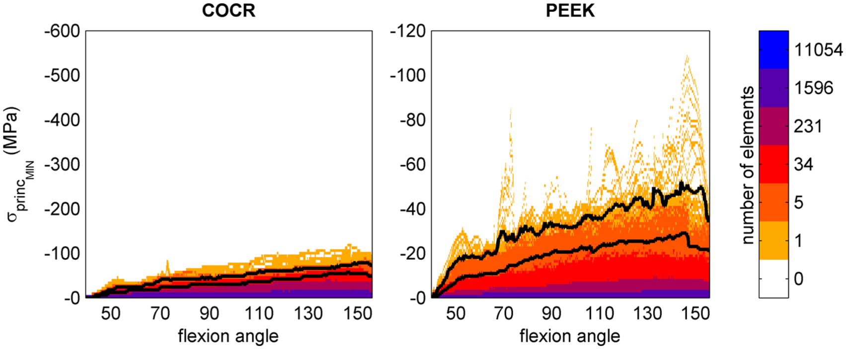
Compressive (minimal principal) stresses in the femoral component throughout the entire squat. Colours represent the number of elements undergoing a certain stress level. The bottom black line marks the stress level below which 99% of the implant elements are loaded, the top black line marks 99.9%.
Results
Stresses in the femoral component
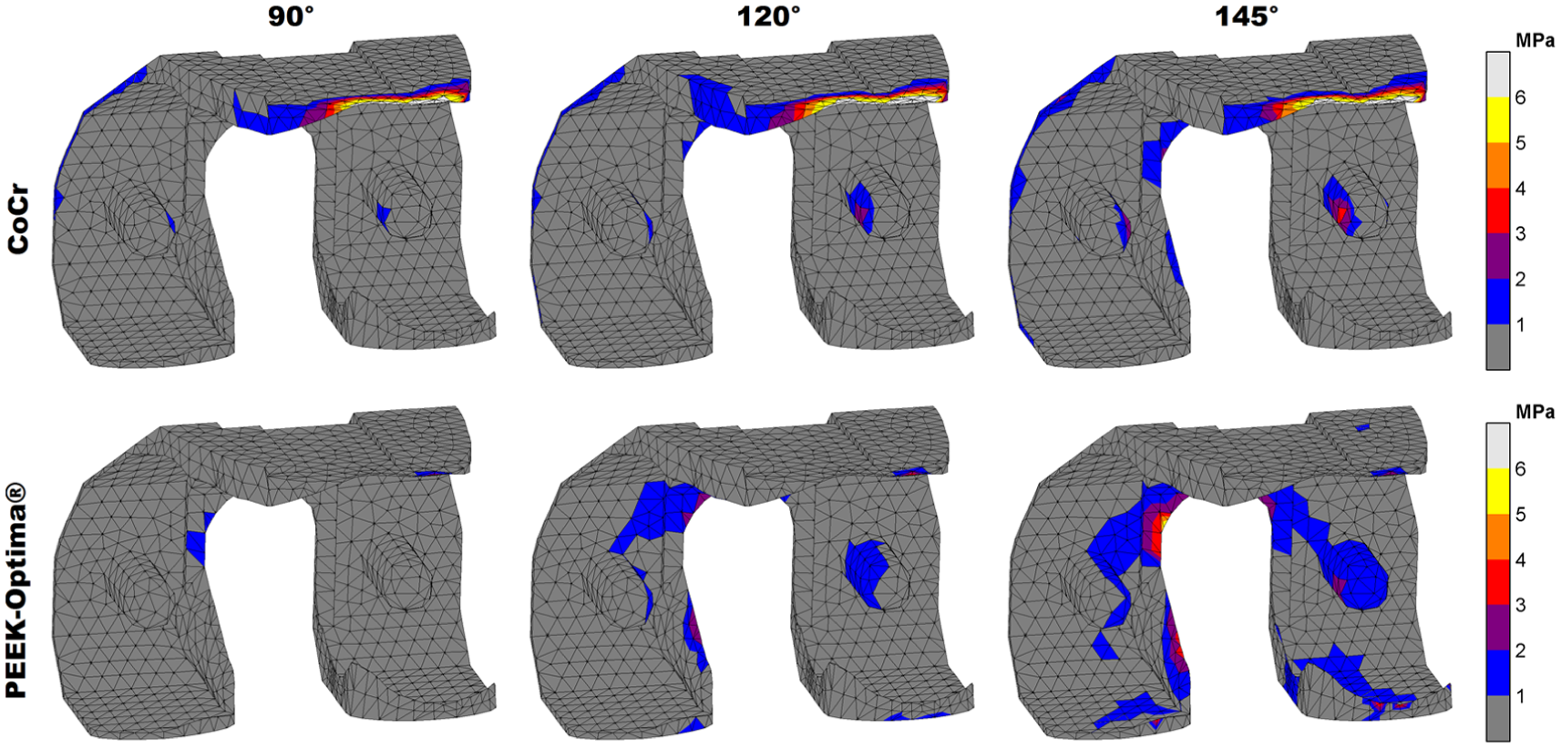
In both implants, the stresses increased with knee flexion. While in the PEEK implant compressive (minimal principal) stresses accumulated in the areas where tibiofemoral and patellofemoral contact takes place, for CoCr, these were distributed more along the implant surface (Figure 3). Moreover, the patellofemoral joint did not generate notable compressive stresses at the CoCr internal surfaces. Overall, absolute compressive stresses in the CoCr implant (60 MPa at 145°) were higher than those found in the PEEK femoral component (30 MPa at 145°). Relative to yield stress, the PEEK implant was subjected to higher compressive stresses than the CoCr implant. The PEEK implant was loaded up to 26% of yield stress versus 10% for CoCr in compressive scenarios.
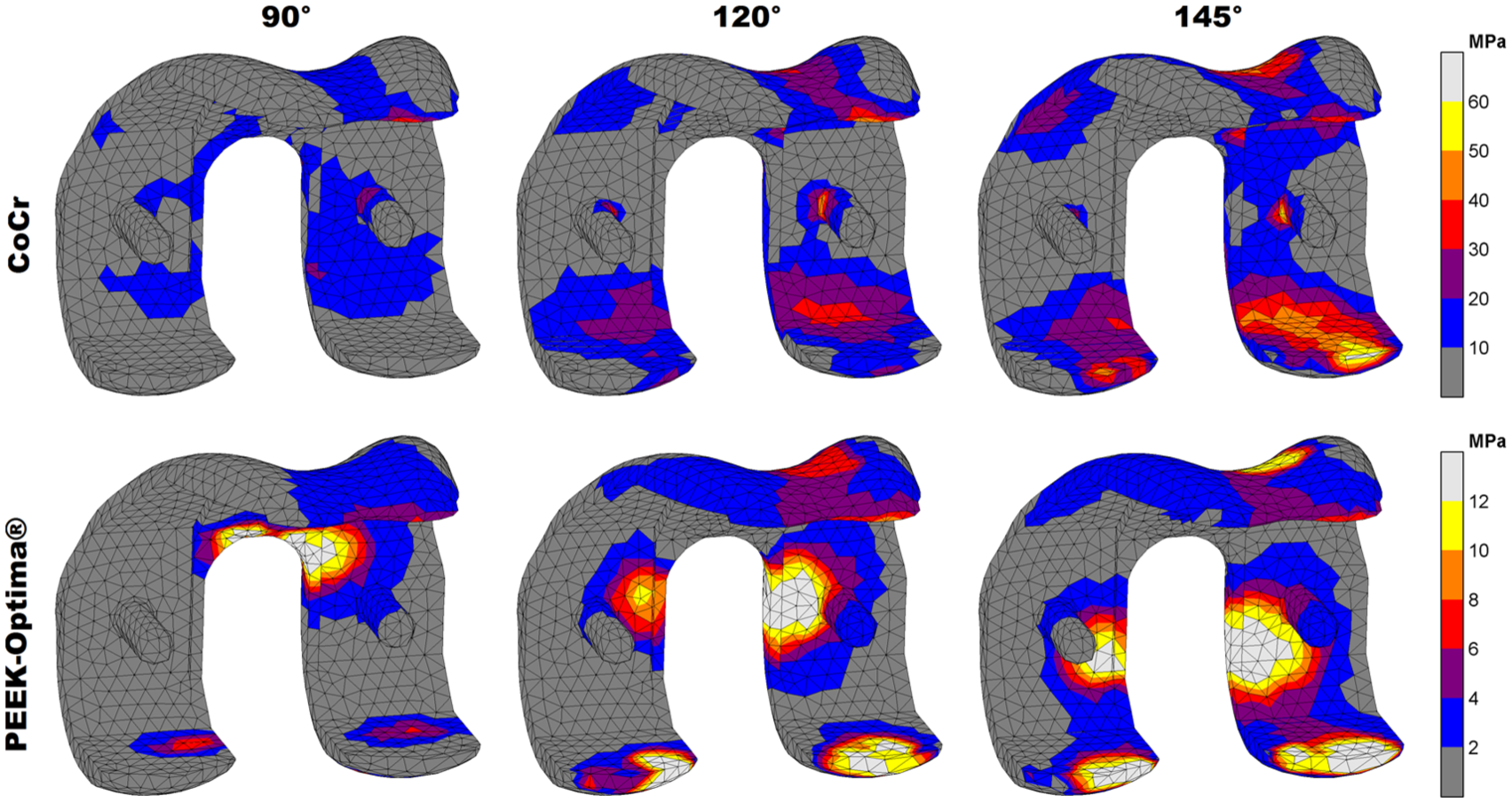
Compressive stress patterns in the femoral component. Stresses are displayed up to 10% of respective yield stress (600 MPa vs 117 MPa) to visualise the distribution at increasing flexion angles.
For tensile (maximal principal) stresses, both absolute and relative stresses were higher in the CoCr implant, which accumulated mostly in the intercondylar notch of both implants. Additionally, the CoCr implant included a stress concentration at the posterior condylar surface, probably caused by bending due to deep flexion tibiofemoral contact. In the PEEK implant, these forces were absorbed locally at the contact site instead of initiating a bending moment in the condyles. The maximum tensile stresses in the implants were 55 MPa (145°) and 4 MPa (120°) for CoCr and PEEK, respectively. Relative to the yield stress, this amounted to 9% for CoCr and 0.4% for the PEEK implant. In total, 83% of the CoCr implant material was subjected to tensile stresses versus 75% of the PEEK device (Figure 4).
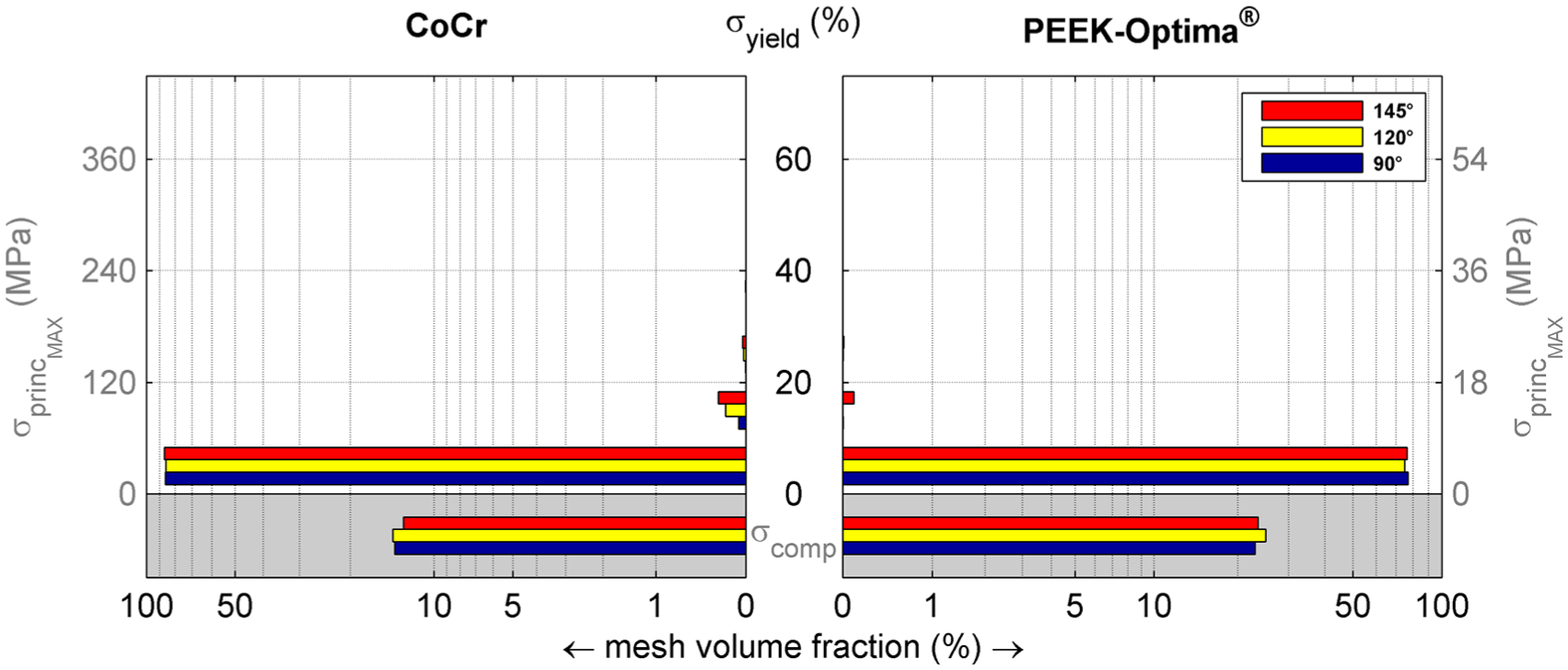
Volumetric distribution of the maximal principal stresses in the femoral component relative to yield stress. The volumes in the grey areas represent parts of the implant that experience no tension. The figure shows that less than 1% of the elements are loaded above 10% of yield stress, and that an increased flexion angle increases the volume loaded at higher stress levels. Note that the horizontal axis has a logarithmic scale to visualise small values.
Stresses in the cement mantle
The more rigid behaviour of the CoCr component was reflected in the cement mantle stresses. No notable compressive (minimal principal) stresses were found along the cement surface of the CoCr device. High compressive stresses were only seen in the most proximal areas of the anterior and posterior flanges. Compressive stresses in the cement were more abundant in case of a PEEK implant. The maximum compressive stresses in the cement mantle underneath the CoCr and PEEK implant were 12 MPa (120°) and 24 MPa (145°), respectively. Relative to the compressive yield stress, this amounted to 12% and 25%, respectively.
Maximal principal (tensile) stresses in the cement were more favourable in the PEEK configuration. Although there were areas of relatively low tensile stresses in the patellofemoral contact region, the cement mantle was largely not subjected to any tensile stress. In the CoCr implant, only small sections of higher tensile loads were found in the proximal tip of the anterior flange (Figure 5). For both implants, less than 1% of the cement mantle was subjected to a tensile stress level which was higher than 20% of the yield stress. The maximum tensile stress levels were more favourable in the ‘PEEK’ cement mantle with 4 MPa at 145° of flexion versus 6 MPa for CoCr at 120°. For CoCr, this stress intensity occurred at the proximal tip of the anterior flange.
Maximal principal stress patterns in the cement mantle. Stresses are displayed up to 15% of yield stress (40 MPa) to visualise the distribution at increasing flexion angles.
Stress shielding of the periprosthetic femur
Relative to the PEEK implant, the CoCr implant clearly had a larger deviation from the intact-SED distribution (Figure 6). The SED reduction was most prominent in the bone adjacent to tibiofemoral contact sites and extended to the posterodistal and anterior regions of the periprosthetic femur. Relatively small differences between PEEK and intact were present: first, the bone directly adjacent to the implant/cement mantle remained slightly strain/stress shielded and second, high strain energy foci, mainly in the areas where tibiofemoral contact occurred, were slightly lowered by the PEEK implant. In general, the PEEK implant showed a high similarity to the intact bone remodelling stimulus throughout the full squatting exercise, with a median reduction in SED of 1% (IQR = 8%). In contrast, CoCr reduced the stimulus by a median of 56% (IQR = 51%).
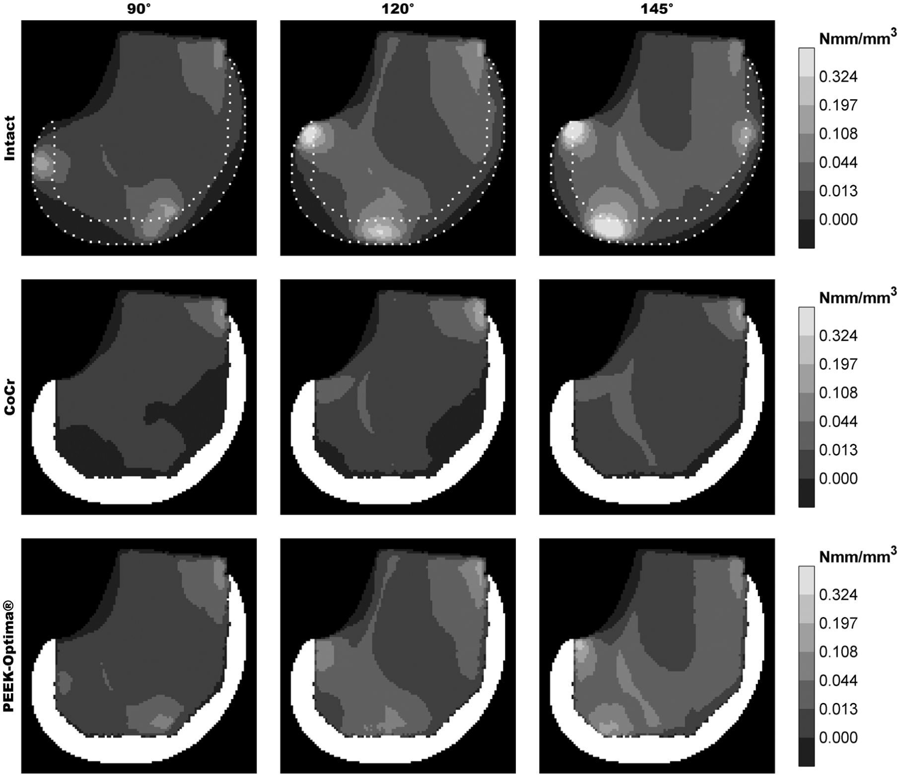
DEXA-like representation of the strain energy density in the periprosthetic volume.
Discussion
The present study aimed to evaluate the mechanical performance of a PEEK femoral component in a high-demand activity such as squatting. Not only should the implant be able to withstand high loads, but also the cement mantle must cope with the changed and increased loading situation under demanding conditions. A deep squat including patellofemoral contact was chosen to investigate the structural integrity of the reconstruction and to evaluate the potential for reduction of the stress shielding phenomenon.11–16 The current results indicate that both implant and cement mantle are not more likely to fail when compared to the CoCr reconstruction. The PEEK implant was able to restore the post-operative bone remodelling stimulus to levels similar to an ‘intact’ femur.
Study limitations
The study was performed by means of the finite element method. For robustness of the model and comparability of the different implant configurations, some assumptions were made. First, the kinetics and kinematics, excluding the influence of the knee capsule, for all three models were the same. The PEEK and CoCr reconstructions may be assumed to behave identically in a kinematic sense, but this may be different for the intact reference model. Both the geometry and kinetics/kinematics were simplified to fit the TKA mesh. It is expected that the influence of geometrical differences, the presence of (cruciate) ligaments and their effect on knee joint mechanics may be substantial, and that therefore the difference in stress and strain patterns between PEEK and intact may be larger than currently modelled. However, clinical and post-mortem bone loss patterns do agree with the regions identified for stress shielding in this study.11–15 The distribution of loads along the bearing surface of the intact knee is further influenced by the articular cartilage and menisci, in contrast to the stiffer and less congruent polyethylene tibial component which generates higher contact stresses.
Second, a simplified bone material model was used. Bone is an anisotropic viscoelastic material, 36 but was modelled as linear elastic isotropic. Young’s moduli were calculated from an uncalibrated CT scan and linearly scaled to a physiological range for distal femoral bone that have been reported in other studies.21–23 Scaling did retain the relative stiffness differences between elements, but local over- or underestimation of the periprosthetic stiffness may have occurred. We believe, however, that due to the comparative nature of this study, the outcome (comparison of PEEK vs CoCr) will hardly be influenced by small deviations in bone stiffness assumptions.
Furthermore, the cement pocket edges and internal surface features of the femoral component were removed (except the pegs) to avoid numerical artefacts at sharp edges. 37 Also, we assumed a homogeneous 1-mm layer of cement, which is the depth of the original cement pockets. In practice, the thickness and coverage of the femoral cement layer are highly variable 38 and could influence local stress intensities. Another influence on the cement mantle outcomes is the zero-friction assumption in the global model. Although the study on which this study’s models were based, determined that friction had a negligible impact on their outcomes, that study did not directly consider cement mantle stresses. 18 The absence of friction may thus have underestimated the cement mantle stresses.
Finally, this FE analysis used a single loading scenario, bone geometry and bone quality. It should be considered that either femoral implant could be more sensitive to changes in these parameters than the other. Although the current results provide insights into the differences between a PEEK and CoCr implant, additional analyses including parametric variations related to patient, implant and surgery are required to draw more robust conclusions.
Stresses in the femoral component
The PEEK implant was more heavily subjected to compressive stresses than the CoCr component, but both remained within the mechanical limits. We analysed case reports of fractured femoral components to find indications of fatigue and to compare crack initiation sites to stress intensities found in the current study.39–45 All implant fractures, metal or ceramics, were attributed to either trauma 39 or tensile fatigue.39–45 The locations of crack initiation were reported to occur at the edges of the posterior chamfers40–42,45 or at the apex of the intercondylar notch.39,43,44 These initiation sites correspond well with our findings for the tensile stress intensities in the CoCr component, while the same patterns in the PEEK implant were of a substantially lower magnitude.
Stresses in the cement mantle
Neither of the reconstructions were largely subjected to critical stress levels, although there were notable differences between CoCr and PEEK. Compressive stresses in the cement mantle were higher for the PEEK implant. Increased cement loading could potentially lead to earlier fatigue failure of the PMMA, although the main difference between the two materials was found for the compressive stress distribution which probably plays a negligible role in fatigue if no pre-existing plastic damage is present.29,30 Conversely, it is known that metal femoral components can loosen, and that this is most likely to be initiated at the anterior flange.18,46 Stress intensities in these areas may thus be considered as a precursor of implant loosening. In the PEEK implant, the tensile stresses in these regions were lower than with CoCr. Moreover, the CoCr component showed a tensile stress intensity at the proximal tip suggesting local loosening or failure may occur in this small region.
Stress shielding of the periprosthetic femur
This study further corroborates the idea that the compliant PEEK implant is capable of lowering periprosthetic stress shielding. This study furthermore suggests that patellofemoral loading at high flexion may prevent loss of anterodistal bone stock in the PEEK implanted case. This effect was visible already at 90° of flexion, making it relevant for the majority of TKA patients who are usually not able to flex beyond 120°,33–35 but can walk the stairs or stand up from a chair or bed. The stress shielding patterns that the CoCr implant imposes on the femur correspond to the areas of bone resorption that have been previously published.11–16,47,48 This is a strong indicator that there is a correlation between the stress shielding that is presented in the current study and bone resorption following remodelling studies, where both clinical DEXA studies11–16 and FE bone remodelling simulations47,48 showed the expected loss of bone mineral density to be most prominent in the anterodistal area and, to a lesser but substantial extent, the posterodistal femur.
Conclusion
This finite element study has identified differences and similarities between CoCr and PEEK TKA reconstructions during high-demand squatting. The current findings demonstrate that (1) a PEEK femoral implant is strong enough to endure high-demand loading, and that (2) with a PEEK implant compressive cement stresses were higher, while tensile cement stresses were reduced. Moreover, the current results suggest that (3) the PEEK device has potential for periprosthetic bone stock retention. Future research should be aimed at corroboration of the data presented in this article via experimental and clinical studies.
Footnotes
Declaration of conflicting interests
L.d.R. and D.J. have no conflicts to declare. A.B. is an employee of Invibio Ltd. N.V. is a consultant for Invibio Ltd. Both A.B. and N.V. were involved in design of the study and review of the manuscript. Invibio Ltd was not involved in the interpretation of the results.
Funding
The author(s) disclosed receipt of the following financial support for the research, authorship, and/or publication of this article: This study is funded by a research grant from Invibio Ltd, Lancashire, UK.