
Abstract
Polyethylene wear is a great concern in total joint replacement. It is now considered a major limiting factor to the long life of such prostheses. Cross-linking has been introduced to reduce the wear of ultra-high-molecular-weight polyethylene (UHMWPE). Computational models have been used extensively for wear prediction and optimization of artificial knee designs. However, in order to be independent and have general applicability and predictability, computational wear models should be based on inputs from independent experimentally determined wear parameters (wear factors or wear coefficients). The objective of this study was to investigate moderately cross-linked UHMWPE, using a multidirectional pin-on-plate wear test machine, under a wide range of applied nominal contact pressure (from 1 to 11 MPa) and under five different kinematic inputs, varying from a purely linear track to a maximum rotation of ±55°. A computational model, based on a direct simulation of the multidirectional pin-on-plate wear tester, was developed to quantify the degree of cross-shear (CS) of the polyethylene pins articulating against the metallic plates. The moderately cross-linked UHMWPE showed wear factors less than half of that reported in the literature for the conventional UHMWPE, under the same loading and kinematic inputs. In addition, under high applied nominal contact stress, the moderately cross-linked UHMWPE wear showed lower dependence on the degree of CS compared to that under low applied nominal contact stress. The calculated wear coefficients were found to be independent of the applied nominal contact stress, in contrast to the wear factors that were shown to be highly pressure dependent. This study provided independent wear data for inputs into computational models for moderately cross-linked polyethylene and supported the application of wear coefficient–based computational wear models.
Keywords
Introduction
Total joint replacement has become a common surgical intervention for the degeneration of natural joints. As these implants have been introduced to younger and more active patient groups, the demands on the joint replacement bearing have increased. To address these additional needs, new designs and materials have been introduced.
The generation of polyethylene wear debris from replacement bearing surfaces is considered to be a major problem for long-term outcome of total joint arthroplasty.1–5 Cross-linking has been introduced to reduce the wear of ultra-high-molecular-weight polyethylene (UHMWPE). Cross-linking may provide significant advantages over conventional UHMWPE, regarding the mechanical and wear properties.6–9 Cross-linking does not only affect the wear resistance but also affects the oxidative stability and fatigue crack propagation.10,11 Different radiation doses and methods, fabrication techniques and heat treatments may result in different mechanical properties.12–14 The wear rate, number and shape of highly cross-linked polyethylene wear particles, isolated from patients’ synovial fluids, were significantly fewer compared to those with conventional polyethylene.15–17
It is important to pre-clinically evaluate the new materials and designs, prior to implantation. Computational wear modelling has been introduced as an additional approach to the experimental studies, which have substantially associated cost and are time-consuming, due to the large number of low-frequency gait cycles that must be run.18–24 The computational wear models are based on either wear factors (k) or non-dimensional wear coefficients (C). The dependence of wear factors and wear coefficients on the applied nominal contact pressure has been reported in the literature.19,25–27 In addition, cross-shear (CS) has been shown to have a significant influence on wear.19,25–30 However, wear factors and wear coefficients should be determined from independent experimental wear tests to provide the predictability for computational wear models.31,32 Previous work has defined wear factors and wear coefficients for conventional polyethylene, which were subsequently applied in computational models. However, some new bearings use cross-linked polyethylene. In total joint replacements, moderately cross-linked UHMWPE materials have been used.33,34
The objective of this study was to experimentally determine the wear factors and wear coefficients of a moderately cross-linked UHMWPE, using a multidirectional pin-on-plate wear test machine. These experimental wear parameters will be inputs to future computational wear modelling of total joint replacement. A wide range of applied nominal contact pressure was tested to cover the range of contact pressure found in knee and hip joint prostheses31,35,36 and to study the effect of applied contact stress on the measured wear factors and wear coefficients. The effect of CS on the measured wear parameters was also considered. A computational model, based on a direct simulation of a multidirectional pin-on-plate wear test machine, was developed to quantify the degree of CS.
Materials and methods
Experimental pin-on-plate wear test
The pin-on-plate wear studies were conducted using the six-station pin-on-plate multidirectional wear test machine, Figure 1(a) (University of Leeds), to determine the wear factors and wear coefficients of a moderately cross-linked UHMWPE pin articulating against cobalt–chrome alloy (CoCr) plate.26,33 In the multidirectional six-station pin-on-plate wear test machine, a rack and pinion gear mechanism transmitted the reciprocating motion of the metallic plate to the pin holder, and hence rotated the pin. The pin rotation and the plate reciprocation resulted in a multidirectional motion at the pin–plate contact surface. 26 The pin and plate motions were in phase, having a common frequency of 1 Hz. Two different gear sizes were used to achieve a larger pin rotation angle.
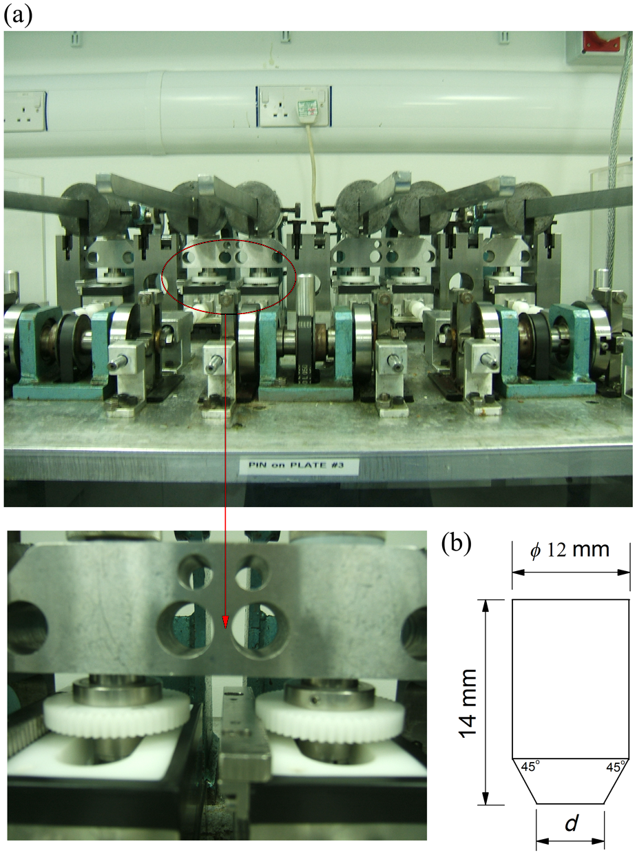
(a) Six-station pin-on-plate multidirectional wear test machine and (b) pin geometry.
The moderately cross-linked UHMWPE pins were machined from tibial inserts, supplied by DePuy (DePuy International Ltd, Leeds, UK), UK. They were XLK material, a GUR 1020 UHMWPE moderately cross-linked with 5 Mrad of gamma irradiation. The pins were loaded against CoCr counter-faces in a flat-on-flat configuration. The cobalt–chrome alloy metallic plates were polished to an average surface roughness Ra ∼0.01 µm. An 80-N load was applied along the longitudinal axis through the centre of the polymer pin, producing a nominal contact pressure corresponding to the cross-sectional area of the pin. Three different pin diameters (d) were used, 3, 5 and 10 mm, as shown in Figure 1(b), which resulted in applied nominal contact stresses of 11, 4 and 1 MPa, respectively. The pins remained in contact with the counter-face throughout the test. The kinematic inputs varied from purely linear tracking up to a rotation of ±55°, with stroke lengths between 12 and 38 mm. Five combinations of pin rotation and plate sliding were tested: (±0°, 28 mm), (±15°, 12 mm), (±30°, 28 mm), (±45°, 26 mm) and (±55°, 38 mm), to cover the wide range of CS ratio reported for total joint replacements, maximum of ∼0.09 and ∼0.18 for knee and hip joints, respectively.37,38 A minimum number of three pins per test condition were tested.
The pin-on-plate wear test was operated in accordance to the standard operating procedure, previously reported in the literature.26,33 The pins were pre-soaked in sterile water for at least 250 h prior to testing, to stabilize their mass change due to moisture absorption. In order to settle the datum points, the test specimens were ultrasonically cleaned using 70% isopropanol/water solution for 10 min before being dried and weighed. The surface profiles were measured prior to testing, using a contacting surface profilometer (Taylor Hobson, Leicester, UK), with a high-pass Gaussian filter at a cut-off of 0.25 and 0.8 mm for the pins and the plates, respectively. A 25% (volume/volume) bovine serum in sterile water was used as a lubricant, equivalent to a protein content of 15 mg/mL, with 0.03% (weight/volume) sodium azide to hinder the bacteria growth during the test. Approximately 50 mL serum solution was placed into each tray and a 0.03% (weight/volume) sodium azide was used to top up each station as required during the test, to maintain the same protein content throughout the test. In order to account for the polyethylene mass change due to water absorption, control pins were soaked, but unloaded, in the identical lubricant to the test specimens for the test duration. The control pins were kept inside the test rig to assure similar environmental conditions as the test pins.
The pins were weighed at the start, end and at regular intervals (330,000 cycles) during the test. After each period of testing (330,000 cycles), the pins and plates were cleaned. Once cleaned, the pins were moved to a room of controlled temperature and moisture and left for at least 48 h to stabilize the polymer. Before each weight, each pin was placed in an ion stream for a minimum of 20 s (Stat Attack IB8; Amersham International plc, UK), to remove any potential static charge. The pins were weighed using a digital microbalance, Mettler AT201 (UK Mettler-Toledo Ltd, Leicester, UK), with a resolution of 1 µg and accuracy ±2 µg. Each pin was weighed until five measurements fell within a ±5 µg range, and the balance was checked for zero error between weights. The control pins were used to adjust the mass losses of the pins due to moisture uptake. The adjusted measured weight loss for each pin was converted into volume loss (W) by dividing with the UHMWPE density of 0.934 mg/mm3. 39 The wear factor (k), for a specific sliding distance (S), was calculated as the volume loss per unit load (L) per unit sliding distance, as shown in equation (1)

Based on the idea that wear volume is proportional to the contact area (A) and sliding distance, a non-dimensional wear coefficient (C) was defined from this formulation 32

Statistical analysis was conducted to express the measured wear factors and wear coefficients as a function of the CS ratio, using analysis of variance (ANOVA) in OriginLab program (Origin 8), in which a P value of less than 0.05 was used to define the significance. In order to best fit the wear factor as a function of average CS, various types of regression methods contained in OriginLab were tested. Three regression methods were specifically examined, including the power law previously used by Kang et al. 26
Computational method to quantify CS
The CS was defined based on the unified theory of wear and frictional work by Wang 29 and the work by Kang et al., 26 as the frictional work component perpendicular to the principal molecular orientation (PMO) direction (E cross -shear ), divided by the total frictional work (E total ), thus

A computational framework was developed for predicting CS of the UHMWPE pins, to simulate its predicting procedure in computational modelling of total joint replacements. The finite element models were developed in ABAQUS (ABAQUS 6.9-EF1), as shown in Figure 2, to simulate the contact and motion of the polyethylene pin relative to the metallic plate, under the same kinematic and loading conditions as the experimental tests. A control node was placed on the axis through the centre of the pin contact surface. The rotation axis was aligned to the loading axis. The pin and the plate contact surfaces were initially brought into contact, to ensure that the surfaces were in full contact before load application and to overcome the convergence problem.
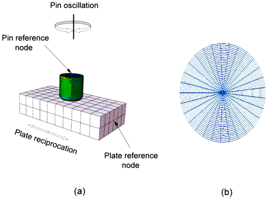
(a) Pin-on-plate wear test ABAQUS model and (b) discretization of pin surface.
A constant load was applied to the reference node of the pin component. The oscillating motion of the pin was also prescribed at that node; all other degrees of freedom were constrained. The reciprocating motion was applied to the plate reference node; all other degrees of freedom were constrained. The reciprocating and oscillating motions were discretized into 50 intervals, representing a loading cycle of 1 s. Discretization sensitivity was studied, based on the predicted average CS; further discretization refinement changed the predicted average CS by less than 5%.
The UHMWPE was modelled as an elastic material, of C3D8R and C3D6 elements type, using the stress–strain data with a modulus of elasticity of 673 MPa and Poisson’s ratio of 0.46 (DePuy, UK). The CoCr modulus of elasticity (∼200 GPa) is much higher than that of UHMWPE, such that the CoCr metallic plate could be modelled as a rigid body, to reduce the computational time required to run the model. Mesh size sensitivity was studied; further mesh refinement changed the predicted contact pressure by less than 5%. The final finite element model contained 20,640 elements for the pin, with a mesh size at the pin contact surface varying from 0.02 to 0.5 mm (Figure 2).
A MATLAB program was developed to calculate the average CS using equation (3). The average CS was used, rather than the CS at the nodes, as the current type of motion (used in the experimental test rig) has variable CS on the pin surface. The PMO direction at each node was defined as the average direction of the corresponding sliding track. 26
Results
The computationally predicted average CS versus the motion input for different pins, under 80-N load, is shown in Figure 3. Changing the kinematic inputs from linear track to (±55°, 38 mm) changed the predicted average CS from 0.0 to 0.254, irrespective of the test pin diameter. The pin diameter had no effect on predicted average CS, over the entire tested motion range. The predicted average CSs were compared to those of Kang et al., 26 for an 8-mm pin and 160-N load, under the same combination of motion. An applied load of 80 N was used, to replicate the experimental conditions, although the nominal applied load had no effect on the predicted average CS.

Computationally predicted average cross-shear ratio versus the type of motion, for different pin diameters (80-N load).
The experimental volume losses of the moderately cross-linked UHMWPE pins versus the number of cycles under applied nominal contact stresses of 1, 4 and 11 MPa are shown in Figure 4(a) to (c), respectively. The first set of each experimental test, for different pin diameters, was run for 3 weeks (∼900,000 cycles). The experimental results of the pin-on-plate wear test demonstrated an approximately linear relation between the measured volume loss and the number of completed cycles. Therefore, it was decided to run the remaining tests for 2 weeks only (∼600,000 cycles). Under the same contact stress, increasing the number of cycles increased the total measured volume loss. For the same number of cycles, the volume loss increased as the type of motion changed from linear tracking to the highest cross-sheared motion combination (±55°, 38 mm). Under the same motion condition, increasing the applied nominal contact stress decreased the measured volume loss. These apparent contradictory results were due to the use of different pin diameters to achieve different nominal pressure levels. The inversely proportional relationship, between volume loss and contact pressure, is in fact a directly proportional relationship between volume loss and contact area.

Moderately cross-linked UHMWPE volume loss versus the number of cycles for different motion combinations (pin rotation, stroke length) under a given applied nominal contact pressure: (a) 1 MPa, (b) 4 MPa and (c) 11 MPa (mean ± SD, n ≥ 3).
The relationship between experimental wear factors and CS under applied nominal contact pressures of 1, 4 and 11 MPa is shown in Figure 5(a) to (c), respectively. Under 1 MPa nominal contact pressure, increasing the degree of CS from 0 to 0.022 increased the corresponding average wear factor rapidly from 4.5 × 10⁻⁸ to 2.3 × 10⁻⁷ mm3/N m. Further increase in the CS up to 0.254 increased the average wear factor, but at a lower rate, to 4.3 × 10⁻⁷ mm3/N m. The best fit of wear factor as a function of CS is summarized in Table 1. The power-1 function had a best statistical adjusted R2 value of 0.99, which reflected a good fit to the overall data.

Moderately cross-linked UHMWPE experimental wear factor versus the cross-shear ratio under applied nominal contact pressures of (a) 1 MPa, (b) 4 MPa and (c) 11 MPa and different curve fitting (mean ± SD, n ≥ 3).
Best fit functions of experimental wear factor as a function of CS, under 1 MPa nominal contact pressure.
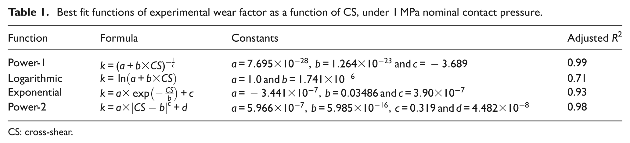
CS: cross-shear.
Under 4 MPa nominal contact pressure, the average wear factor rapidly increased from 1.4 × 10⁻⁸ to 1.8 × 10⁻⁷ mm3/N m corresponding to a CS of 0 and 0.022, respectively. After this point, for any further increase in the degree of CS, the average wear factor remained nearly constant. Among the different regression methods used to fit the wear factor as a function of CS, the exponential function had a best statistical adjusted R2 value of 0.99. The power-1 function had a statistical adjusted R2 value of 0.96. The power-2 and the logarithmic functions had statistical adjusted R2 values of 0.92 and 0.87, respectively.
The relationship between wear factor and CS under 11 MPa is shown to have the same trend as that under 4 MPa. The average wear factor showed a rapid increase from 1.8 × 10⁻⁸ to 1.2 × 10⁻⁷ mm3/N m, related to an increase in the degree of CS from 0 to 0.022, followed by fluctuation around a constant value of 1.2 × 10⁻⁷ mm3/N m, over the remaining test range. The exponential function had the best statistical adjusted R2 value of 0.96. The power-1 function had a statistical adjusted R2 value of 0.69. The power-2 and the logarithmic functions had statistical adjusted R2 values of 0.51 and 0.14, respectively.
The 1 MPa experimental wear factors of the moderately cross-linked UHMWPE are compared to that of conventional UHMWPE,26,30 under the same applied nominal contact pressure, as shown in Figure 6. For the same CS, the measured wear factor for the conventional UHMWPE was higher than the corresponding wear factor of moderately cross-linked UHMWPE. For example, the conventional UHMWPE wear factors were ∼9 × 10⁻⁷, 1.3 × 10⁻⁶ and 9 × 10⁻⁷ mm3/N m corresponding to CSs of 0.087, 0.18 and 0.254, respectively, compared to ∼3 × 10⁻⁷, 4.4 × 10⁻⁷ and 4.3 × 10⁻⁷ mm3/N m for moderately cross-linked UHMWPE, respectively.

Experimental wear factor versus the cross-shear ratio under 1 MPa applied nominal contact pressure for the conventional 30 and moderately cross-linked UHMWPE (mean ± SD, n ≥ 3).
The measured wear factor versus the applied nominal contact pressure, under different CSs, is shown in Figure 7(a). The P value between different applied nominal contact pressures, under the same CS, was less than 0.05, this significant difference shows the wear factor–pressure dependence relationship. Under the same CS, the wear factor decreased as the applied nominal contact pressure increased. For a CS of 0.254, as an example, the measured wear factors were 4.26 × 10⁻⁷, 2.30 × 10⁻⁷ and 1.10 × 10⁻⁷ mm3/N m corresponding to applied nominal contact stress of 1, 4 and 11 MPa, respectively. Similar trend was found by Kang et al. for the conventional polyethylene.26,30 The average wear coefficient for the moderately cross-linked UHMWPE, over different CSs, versus the applied nominal pressure is shown in Figure 7(b). The experimental average wear coefficient was found to be much less dependent on pressure.

Moderately cross-linked UHMWPE experimental (a) wear factors, for different cross-shear ratios (mean ± SD, n ≥ 3), and (b) wear coefficients (mean ± SD, n ≥ 15) versus the applied nominal contact pressure.
The relationship between the average wear coefficient, over applied nominal contact pressure, and CS is shown in Figure 8(a). The P value between different applied nominal contact pressures, under the same CS, was greater than 0.05, showing insignificant difference, therefore the dimensionless wear coefficients were averaged over the applied nominal contact pressure, for the same CS. Increasing the degree of CS from 0 to 0.022 increased the corresponding average wear coefficient rapidly from 9.9 × 10⁻¹¹ to 7 × 10⁻¹⁰. The wear coefficient remained almost constant at 8.7 × 10⁻¹⁰, while increasing the CS to a maximum of 0.254. The best fit of wear coefficient as a function of CS is summarized in Table 2. The power-1, power-2 and the exponential functions had the same best statistical adjusted R2 value of 0.98. The wear coefficients of moderately cross-linked UHMWPE were compared to those of conventional UHMWPE in Figure 8(b).26,31 Over the tested range, moderately cross-linked UHMWPE had lower wear coefficients compared to conventional UHMWPE. The measured wear coefficients for the conventional UHMWPE were ∼9 × 10⁻¹⁰, 1.1 × 10⁻⁹ and 1.3 × 10⁻⁹ corresponding to CSs of 0.022, 0.087 and 0.254, while the corresponding wear coefficients for moderately cross-linked UHMWPE were ∼7 × 10⁻¹⁰, 8.5 × 10⁻¹⁰ and 8.7 × 10⁻¹⁰, respectively.

Best fit functions of experimental average wear coefficient, over applied nominal contact pressure, as a function of CS.
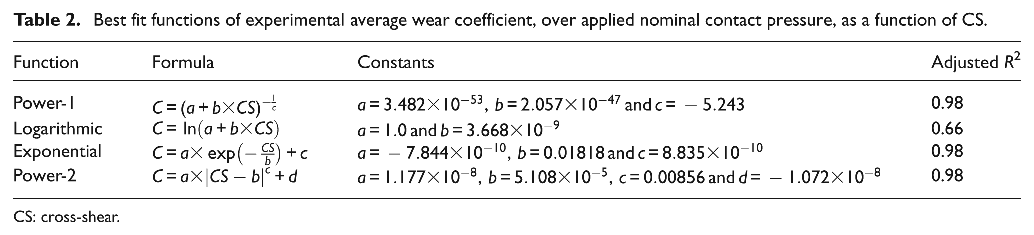
CS: cross-shear.
Discussion
New materials and designs are introduced to reduce the joint replacement wear and improve functionality. These new designs and materials should have preclinical assessment prior to implantation. Experimental and computational methods are used to evaluate new materials as well as new designs. The experimental methods are costly and time-consuming compared to the computational evaluation methods. In addition, computational methods are suitable for parametric studies. However, computational methods should be experimentally validated. One of the validation methods is to experimentally calculate the input parameters independently, that is, wear factors or wear coefficients. In addition, factors that have effects on these input parameters, such as CS and applied nominal contact pressure, should be considered, as in this study.
In this study, the pin rotation angle was shown to play a major role in CS prediction for moderately cross-linked UHMWPE (Figure 3). For example, changing the kinematic input from (±30°, 28 mm) to (±45°, 26 mm) doubled the predicted average CS, although the stroke length was only reduced by 2 mm. On the other hand, changing the kinematic input from (±45°, 26 mm) to (±55°, 38 mm) increased the predicted average CS by 40% of its original value, although the stroke length was increased by 12 mm. The computationally predicted average CSs were compared to those of Kang et al., 26 under the same kinematic inputs, and the results were similar.
When the wear factor was considered, a directly proportional relationship between wear factor and CS dominated, under different applied nominal contact pressure, as shown in Figure 5. Wear factors were shown to peak around the CS value of 0.18. This finding is consistent with the results by Saikko et al. 40 and Korduba and Wang. 9 Wang’s model of strain hardening suggests that orientation occurs in the PMO direction, resulting in molecular softening in the direction perpendicular to the PMO direction. However, molecular alignment may occur in both motion directions at high CS ratios. 9 Higher CS tests are required to investigate this phenomenon, which are not realistically adopted in both experimental and computational total joint replacement wear tests. More importantly, the measured wear factors under multidirectional motions (CS ≠ 0) were more than five times the corresponding wear factors under unidirectional motion, depending on the applied nominal contact pressure and the degree of cross-shearing. This emphasizes the important effect that CS has on wear prediction and may explain the lower wear prediction of computational wear models, based on wear factors from unidirectional wear testers, compared to clinical and multidirectional wear factor–based predictions. The directly proportional relationship found between wear factor and CS turned out to be an inversely proportional relationship between wear factor and applied nominal contact stress for the same CS, as shown in Figure 7(a). Increasing the applied nominal contact pressure from 1 to 4 MPa and from 1 to 11 MPa decreased the corresponding wear factor by 17%–69% and 47%–74%, respectively, depending on the CS. The high dependence of wear factors on the applied nominal contact pressure may explain the wide range of wear factors found in the literature. 31 The measured wear factors for moderately cross-linked UHMWPE, under 1-MPa applied nominal contact pressure, were found to be less than half of their corresponding conventional UHMWPE values, under the same applied nominal contact pressure and CS (Figure 6). Moreover, the lower dependence of the moderately cross-linked UHMWPE on the degree of CS, than the conventional UHMWPE, may prove advantage for cross-linking in decreasing the effect of orientation softening. 9 These findings are consistent with other studies that suggested that using cross-linked UHMWPE as a bearing material in artificial joint replacements may significantly reduce wear in such prostheses.15,17,33,34,41–43
On the wear coefficient scale, the measured non-dimensional wear coefficients under cross-sheared kinematic inputs were more than seven times the non-cross-sheared coefficients, as shown in Figure 8(a). In addition, the wear coefficient was found to be highly pressure independent (Figure 7(b)), which is an advantage over the pressure-dependent wear factors, over the tested contact pressures. Moreover, the pressure independency of the wear coefficient makes it a more reliable and robust wear parameter. Therefore, such an approach can be applied to compare different materials in the future. A reduction in the measured wear coefficients from 23% to 67%, depending on the CS, was detected when the moderately cross-linked UHMWPE was compared to the conventional UHMWPE,26,30 as shown in Figure 8(b). This emphasizes again the advantage of cross-linked UHMWPE over the conventional UHMWPE as a bearing material.
Conclusion
This study generated wear factors and wear coefficients of a moderately cross-linked UHMWPE, which may be used as independent input data for computational wear models. The wear of moderately cross-linked UHMWPE, considered in this study, was found to be less dependent on the degree of CS, compared to conventional UHMWPE. This study suggests that the pressure-independent wear coefficient may be the future key parameter to compare different materials on wear resistance.
Footnotes
Funding
A. Abdelgaied was supported by The Egyptian Ministry of Higher Education & Scientific Research (Helwan University). This research work is supported by Wellcome EPSRC Leeds Medical Engineering Centre (WELMEC), funded by the Wellcome Trust and EPSRC (WT088908/Z/09/Z) and the Leeds Musculoskeletal Biomedical Research Unit (LMBRU), funded by NIHR (J. Fisher is an NIHR senior investigator).
Conflict of interest
J.Fisher is a consultant to DePuy International Ltd, UK, a Director and share holder of Tissue Regenix plc and BITECIC Ltd and a Director of Medilink. C. Brockett is a consultant to DePuy International Ltd, UK.