
Abstract
Few biomechanical studies exist on femoral cementless press-fit stems for revision total knee replacement (TKR) surgeries. The aim of this study was to compare the mechanical quality of the femur–stem interface for a series of commercially available press-fit stems, because this interface may be a ‘weak link’ which could fail earlier than the femur–TKR bond itself. Also, the femur–stem interface may become particularly critical if distal femur bone degeneration, which may necessitate or follow revision TKR, ever weakens the femur–TKR bond itself. The authors implanted five synthetic femurs each with a Sigma Short Stem (SSS), Sigma Long Stem (SLS), Genesis II Short Stem (GSS), or Genesis II Long Stem (GLS). Axial stiffness, lateral stiffness, ‘offset load’ torsional stiffness, and ‘offset load’ torsional strength were measured with a mechanical testing system using displacement control. Axial (range = 1047–1461 N/mm, p = 0.106), lateral (range = 415–462 N/mm, p = 0.297), and torsional (range = 115–139 N/mm, p > 0.055) stiffnesses were not different between groups. The SSS had higher torsional strength (863 N) than the other stems (range = 167–197 N, p < 0.001). Torsional failure occurred by femoral ‘spin’ around the stem’s long axis. There was poor linear correlation between the femur–stem interface area versus axial stiffness (R = 0.38) and torsional stiffness (R = 0.38), and there was a moderate linear correlation versus torsional strength (R = 0.55). Yet, there was a high inverse linear correlation between interfacial surface area versus lateral stiffness (R = 0.79), although this did not result in a statistical difference between stem groups (p = 0.297). These press-fit stems provide equivalent stability, except that the SSS has greater torsional strength.
Introduction
Stems are commonly recommended for revision total knee replacement (TKR) surgery.1–10 The reason is that stem extensions have improved survivorship time and clinical outcomes of revision surgery for TKRs.1–4,11 Revision TKR surgery is a difficult procedure that requires the use of stem extensions to allow for endosteal referencing, bypassing of bone defects, and reduction of interface stresses of damaged bone in the distal femur or proximal tibia. 12 Although some investigators believe that cemented fixation of stems is the best choice to achieve optimal clinical outcome and mechanical stability for revision TKR surgery,7,13,14 other researchers have shown that cementless stems can have mechanical superiority or equivalence relative to cemented devices.1,6
One advantage of cementless press-fit stems is that they allow for quicker and easier insertion into the femoral canal without the additional preparation time, handling, and cost required by cement. Cementless stems can also be more easily removed, compared to cemented devices, if complications arise later on, such as pain or infection. Cementless stem survivorship for revision TKR surgery is similar to cemented stems, with satisfactory radiographic results regardless of constraint, stem size, or augmentations. 12 Cementless stems, particularly the longer variety, can achieve superior or equivalent mechanical stability relative to cemented stems.1,6 The incidence of end-of-stem pain was reported to be lower in slotted titanium stems than in solid cobalt-chrome stems, both designs being cementless. 15 Yet, compared to cemented devices, cementless stems have shown greater micromotion in some studies7,13,14 and are reported to have a higher rate of loosening (29% vs 7%). 5 A recent computational study assessed press-fit cementless versus cemented stems for revision TKR surgery regarding load sharing properties and suggested that press-fit stems are adequate if structural allografts for femur revision are employed. 16 Also, a recent experimental report showed that sliding stems can provide sufficient stability, while minimizing stress shielding since the compressive contact forces are still transferred to the distal femur. 17 It appears that the choice of which stem design or operating principle is optimal for revision TKR surgery is a matter of ongoing investigation in the literature. Moreover, there are no prior biomechanical investigations specifically comparing the performance of a variety of femoral cementless press-fit stems for revision TKR surgery.
The purpose of this study, therefore, was to directly compare the biomechanical stability of the femur–stem interface of the Sigma Short Stem (SSS), Sigma Long Stem (SLS), Genesis II Short Stem (GSS), and Genesis II Long Stem (GLS) cementless press-fit stems used in revision TKR surgery. Measurements were made of axial stiffness, lateral stiffness, torsional stiffness, and torsional strength. It was hypothesized that stems which engaged more of the femoral canal surface area would mechanically outperform other stems.
Methods
Overall testing strategy
Twenty synthetic femurs were evenly distributed into four groups of five specimens each. They were then implanted with four different commercially available cementless press-fit stems used clinically for revision TKR surgery. Specimens were mechanically tested to obtain axial, lateral, and torsional stiffnesses, as well as torsional strength. As a result, only the femur–stem interface was assessed without the presence of a TKR, because this interface may be a ‘weak link’ that could fail earlier than the femur–TKR bond itself in a clinical scenario. Also, degeneration of distal femur bone stock, which may necessitate revision or follow it, could weaken the femur–TKR bond, making the strength of the femur–stem interface that much more critical in providing mechanical stability. Moreover, similar test regimes and parameters as described below have been used in previous studies on synthetic and human femurs,18–23 one of which on press-fit stems was especially used as a guideline for the present study. 24 Stiffness and strength were measured currently because they are very common parameters for in vitro biomechanical studies on bone-implant constructs.18–22,24–28 They are performed to assess the global properties of bone-implant constructs immediately postoperatively. Specifically, stiffness is useful in understanding bone-implant behavior during low loads, say, during common physician-prescribed precautionary ‘toe touch’ weight-bearing immediately following orthopedic surgery. Stiffness is also a helpful criterion to predict and compare the prefailure mechanical stability of bone-implant constructs during normal activities of daily living that do not cause injury. Strength indicates the maximum load that can fail the bone-implant system, say, during full weight-bearing and ambulation. Stiffness and strength served as preliminary measurements, which should be followed up with more detailed assessments using other techniques.14,16,17
Specimen preparation
Twenty medium, left, synthetic femurs were used (Model #3303; Sawbones, Vashon, WA, USA), having a midshaft outer diameter of 27 mm and inner canal diameter of 13 mm. The femurs were randomly assigned to four groups of five femurs each (Figure 1). The stem groups were the SSS (DePuy Orthopaedics, Inc., Warsaw, IN, USA) (diameter = 20 mm, length = 125 mm), SLS (DePuy Orthopaedics, Inc.) (diameter = 14 mm, length = 175 mm), GSS (Smith & Nephew, Memphis, TN, USA) (diameter = 20 mm, length = 150 mm), and GLS (Smith & Nephew) (diameter = 14 mm, length = 200 mm). Femoral condyles were severed. As commonly done clinically and as recommended by most manufacturers, canals were reamed ‘line to line’ to match the stem diameters, and the stems were inserted into the femurs. This allowed for the best rudimentary interference fit. From clinical and laboratory experience, the authors found that undersizing or oversizing by 1 mm (i.e. 1 size) created poor stem fits in human and synthetic femurs. A 10-mm portion of each stem that protruded distally was transversely drilled and a pin inserted to allow for adequate gripping into distal cement blocks. The long axes of the femurs were mounted into a multiaxial clamping system and aligned vertically in the frontal and sagittal planes using a leveling gage. The distal portion of the stems with the pins was then potted using anchoring cement (Flowstone; King Packaged Materials Company, Burlington, ON, Canada) in square steel cubes (75 mm high × 88 mm long × 88 mm wide). The final working length from the top of the cement block to the top of the femoral head was the same for each specimen at 399 mm. This concurs with the clinical practice of adding distal augments to femurs based on bone loss in order to preserve the overall femur length. Based on stem geometry (minus the distal 10-mm portion used for potting), the theoretical surface areas engaged at the femur–stem intramedullary interfaces from the top of the cement potting block to the tip of the stems were 7226 mm2 (SSS), 7257 mm2 (SLS), 8796 mm2 (GSS), and 8357 mm2 (GLS). Moreover, based on stem lengths (minus the 10-mm distal portion used for potting) relative to the final working length of the femurs, the stems were inserted to depths of about 29% (SSS), 41% (SLS), 35% (GSS), and 48% (GLS) (Figure 2). These calculations do not account for any surface texturing effects or the presence of recessed areas, but are only an initial estimate based on the nominal length and diameter of the stems. For the immediate postoperative situation, a more precise estimate of stem outer surface area would subtract textured or recessed portions of the stems which are not likely to come into direct contact with the inside surface of the femoral canal. The present surface area estimates may be more representative of the long-term situation, in which bone remodeling may occur around the stems’ textured portions and into the stems’ recesses, thereby maximizing the femur–stem contact surface area.
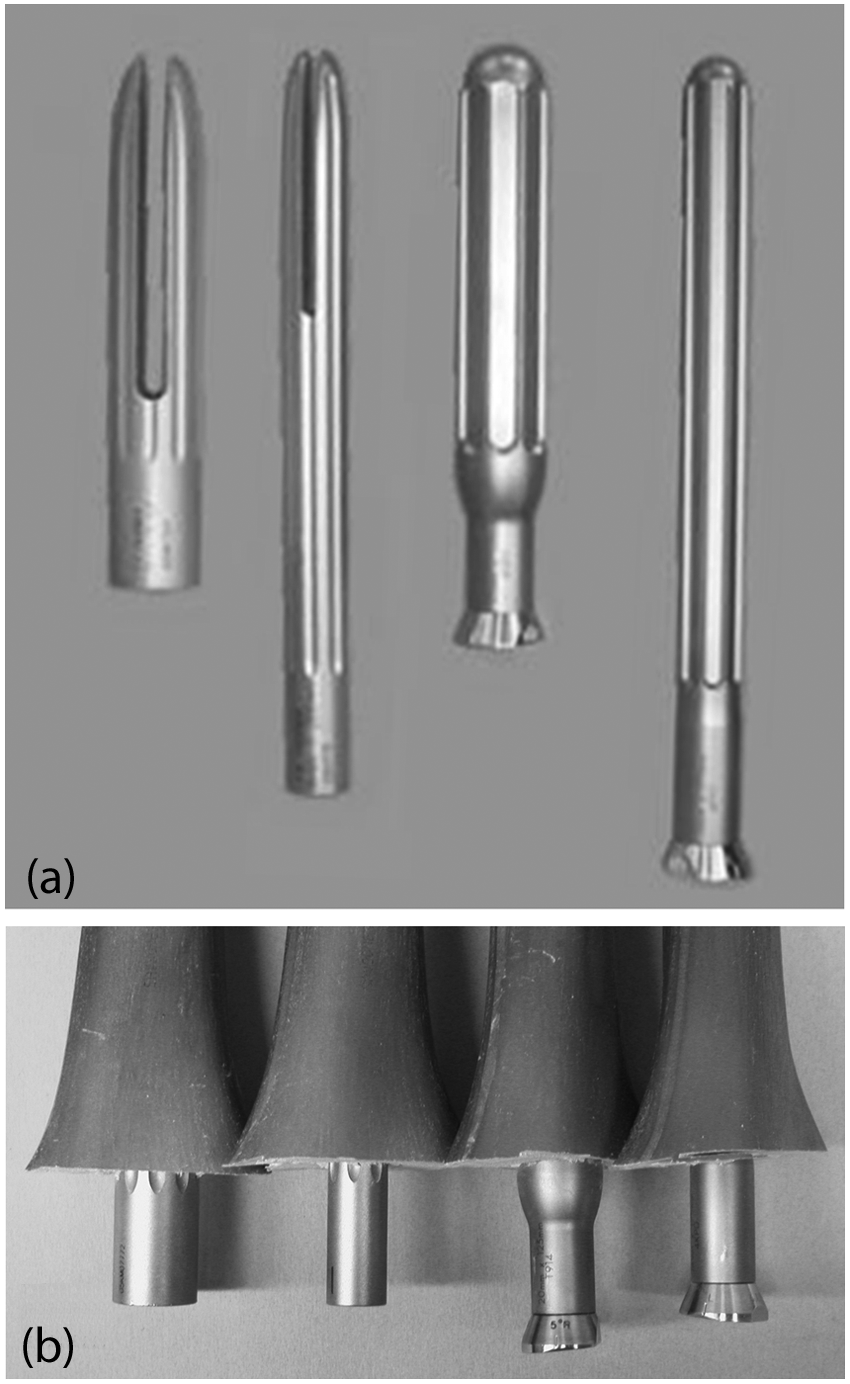
Photos of (a) the cementless press-fit stems and (b) the stems implanted into the augmented distal ends of the synthetic femurs. From left to right: the Sigma Short Stem, Sigma Long Stem, Genesis II Short Stem, and Genesis II Long Stem.
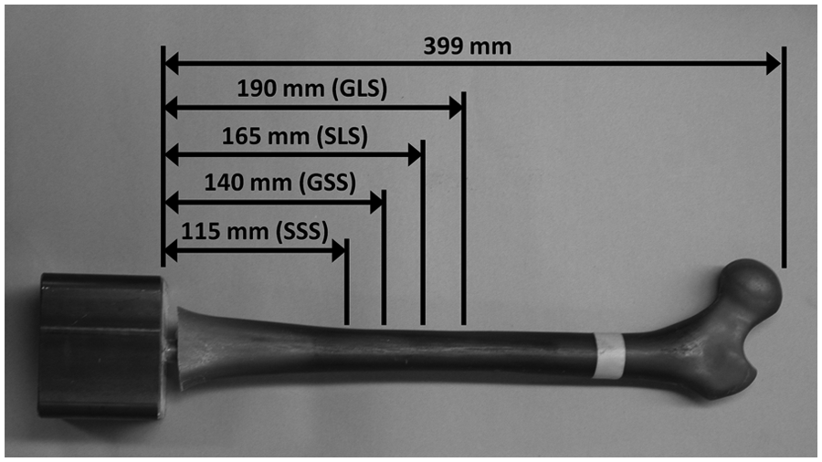
The insertion depths of the press-fit stems relative to the overall working length of the synthetic femurs were SSS (29%), SLS (41%), GSS (35%), and GLS (48%).
Axial stiffness tests
Each femur was oriented vertically in frontal and sagittal planes with no anteversion relative to the loading machine (Figure 3). This simulated the single-legged stance phase of walking, as done in previous studies.18–24 Distally, the cement pot was secured in an industrial vice. Proximally, the femur heads were inserted into a smooth cup cut out of a stainless steel block, which was oriented with no anteversion with respect to the femoral neck. Femur heads were not fixed, but were allowed to rotate inside the cup. Vertical loads were subsequently applied at the femoral heads using displacement control with a linear ramp-up/ramp-down waveform (maximum displacement = 0.25 mm, rate = 10 mm/min, preload = 100 N). The slope of the linear portion of the force-versus-displacement graph was defined as the average axial stiffness. For each specimen, the stiffness was obtained from an average of three trials, which also ensured result reproducibility. Femurs were within the linear elastic region to avoid permanent damage, with a mean linearity coefficient of R2 = 0.95
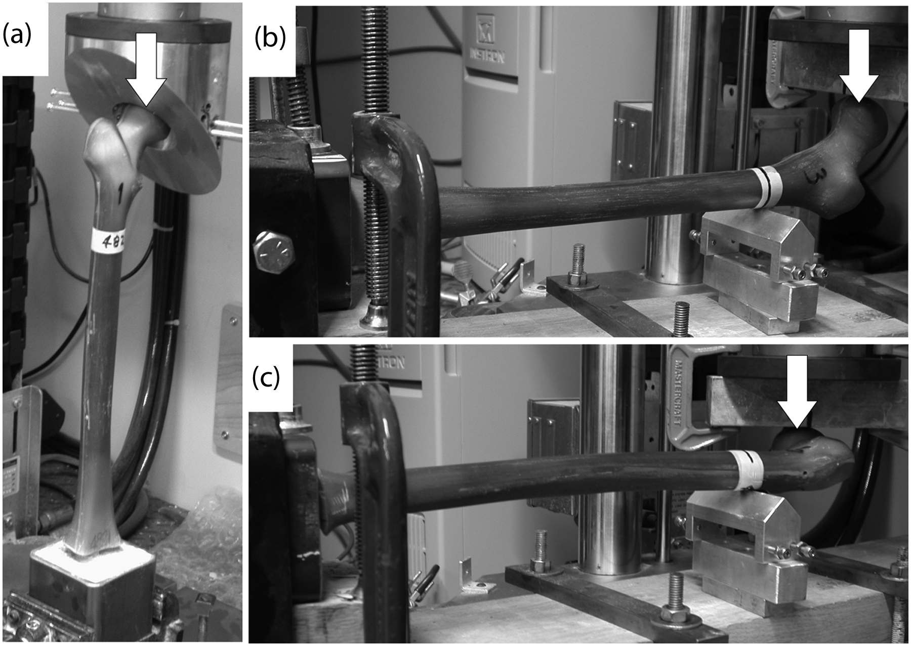
Mechanical testing modes: (a) axial compression, (b) lateral bending, and (c) torsion. White arrows show the direction of force application on the femoral head.
Lateral stiffness tests
Femur specimens were mounted horizontally onto a test jig with the femoral heads oriented upright (Figure 3). Femoral heads were free to slide under a load application metal plate, while a triangular support block was placed 300 mm proximal to the top of the cement pot in order to minimize long-axis bending. Vertical loads were applied to the inferior side of the femoral head to create lateral bending using displacement control (maximum displacement = 0.5 mm, rate = 10 mm/min, preload =100 N). This simulated a lateral force on the femur as might occur during an injury mechanism, as done in previous studies.18–24 The slope of the linear portion of the force-versus-displacement graph was defined as the lateral stiffness. For each specimen, the stiffness was obtained from an average of three trials, which also ensured measurement reproducibility. Femurs were maintained within the linear elastic region to avoid permanent damage, with a mean linearity coefficient of R2 = 0.97.
Torsional stiffness tests
Femurs were mounted horizontally onto a test jig with the posterior side oriented downward (Figure 3). Femoral heads were free to slide under a metal plate used for load application, while a triangular support block was placed 300 mm proximal to the top of the square potting chamber to minimize long-axis bending and allow for internal rotation of the femoral head. A vertical ‘offset load’ was applied to the anterior side of the femoral head to create internal rotation around the long axis of the femur using displacement control (maximum displacement = 0.25 mm, rate = 10 mm/min, preload = 50 N). The slope of the linear portion of the force-versus-displacement graph was defined as the torsional stiffness. For each specimen, the stiffness was obtained from an average of three trials, which also ensured result reproducibility. It should be made clear that the ‘offset torsion’ employed was actually a combination of pure torsion around the long axis plus some long-axis bending of the femur at the support block; thus, the load cell measured the vertical displacement of the femoral head for a given vertical load level. This resulted in N/mm units, rather than Nm/deg units; however, this approach is commonly used in biomechanical studies as a surrogate for pure torsion.18–24 Femurs were kept within the linear elastic region to avoid permanent damage, with a mean linearity coefficient of R2 = 0.97.
Torsional strength tests
Torsional strength during internal head rotation for each femur was determined by applying a vertical ‘offset load’ as described above for torsional stiffness tests (Figure 3). The load was increased until failure of the femur, stem, or femur–stem interface occurred, as done in a prior study. 24 Any catastrophic fracture patterns on the bone were examined and noted. A specimen was considered to have undergone initial clinical failure either when the first sudden 10% drop in applied force was experienced after reaching a peak load (which indicated significant initial structural collapse of the femur and/or stem) or when a plateau in load was evident (which indicated spinning of the femur around the stem’s long axis).
Mechanical tester
All experiments were done on the same materials testing system (Model 8874; Instron, Norwood, MA, USA). The load cell had a linear capacity of ±25 kN, a resolution of 0.1 N, and an accuracy of ±0.5%. The load frame had a linear stiffness of 260 kN/mm, which was much higher than expected for the specimens; thus, there was no compensation for Instron compliance. Moreover, the authors ensured that all jigs and fixtures were rigid and used consistently from specimen to specimen.
Statistical analysis
Single-factor one-way analyses of variance (ANOVAs) were performed to compare the axial compression stiffness, lateral bending stiffness, torsional stiffness, and torsional strength between press-fit specimens with a significance level of p < 0.05. Tukey’s honestly significant difference test was used for all post hoc analysis at a level of p < 0.05 to detect which, if any, specific pairwise comparisons caused a statistical difference. Tukey’s test is commonly used when the same number of specimens is assigned to each test group, as was the case currently. Linear correlation coefficients were calculated to determine if there was any relationship between interfacial femur–stem surface area engaged versus stiffness and strength. A two-tailed post hoc power analysis was finally done to determine if there were enough femurs per test group to detect all statistical differences actually present, that is, to avoid type II error.
Results
Stiffness and strength
All stiffness and strength results have been tabulated (Table 1). For axial stiffness, there was no statistically significant difference noted between any of the specimens (p = 0.106). The SSS value was at most 40% greater than the other stems, but the other three stems were within 13% of each other. For lateral stiffnesses, there was no statistically significant difference detected between any of the specimens (p = 0.297), and the values were within 10% of each other. For torsional stiffnesses, there was no statistically significant differences observed between any of the specimens (p > 0.055), and the values were within 17% of each other. For torsional strength, there were no statistically significant differences observed between the SLS, GSS, or GLS (p > 0.986), and their values were within 18% of each other. However, the SSS demonstrated a much higher torsional strength than all other stems (p < 0.001).
Stiffness and strength results.
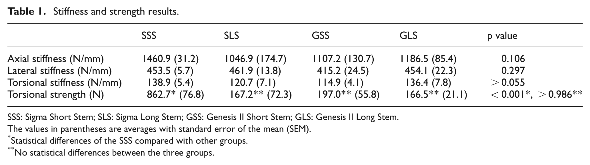
SSS: Sigma Short Stem; SLS: Sigma Long Stem; GSS: Genesis II Short Stem; GLS: Genesis II Long Stem.
The values in parentheses are averages with standard error of the mean (SEM).
Statistical differences of the SSS compared with other groups.
No statistical differences between the three groups.
Torsional failure modes
Force-versus-time traces for the press-fit constructs during failure tests showed that failure for almost all specimens from all groups occurred by the same mechanism (Figure 4). The failure mode most common to the constructs was ‘spin’, in which the femurs began to undergo pure rotation around the stem’s long axis. This behavior was characteristic of congruent sliding between two mating surfaces. A relatively linear increase in force occurred until the static femur–stem interfacial friction was surpassed. The force then plateaued for a substantial period of time to indicate the onset of pure spin. Torsional strength was defined as the average force value during the first segment that showed a plateaued force level, which varied between specimens. Beyond this plateau region, some specimens showed increased force values, but this was not due to torsional motion anymore, since the femoral head had spun around considerably and was simply being pushed on its lateral aspect by the metal plate. Only two specimens, both from the SSS group, deviated from this pattern and experienced a spiral fracture of the femurs at the distal end without any evidence of spin.
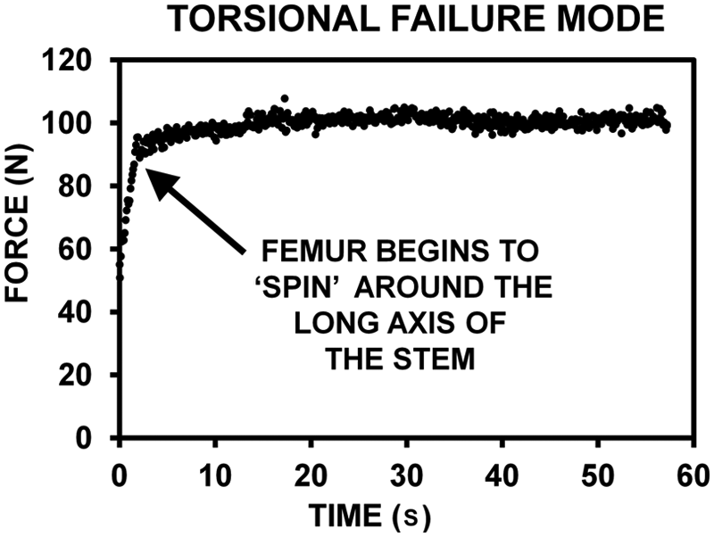
Typical force-versus-time graph during torsional strength testing. The force increased linearly until the static friction between the femur and stem was overcome, which was followed by a leveling off of the force value during pure rotational ‘spin’ of the femur around the stem.
Correlation of results with femur–stem interface area
There was a low Pearson linear correlation coefficient between total surface area engaged at the femur–stem interface versus axial (R = 0.38) and torsional (R = 0.38) stiffnesses, and there was only a moderate Pearson linear correlation versus torsional strength (R = 0.55). However, there was a high inverse Pearson linear correlation coefficient between interfacial surface area versus lateral stiffness (R = 0.79), although this did not result in a statistical difference between stem groups (p = 0.297).
Post hoc power analysis
The post hoc power results yielded averages of 42% (axial stiffness), 19% (lateral stiffness), 45% (torsional stiffness), and 53% (torsional strength). A good study design is considered to have a minimum power of about 80%, suggesting that lateral stiffness analysis especially did not detect all statistical differences actually present. The other measurements were more successful in detecting the statistical differences present.
Discussion
General findings
The current investigation found that stiffness was equivalent for the four press-fit stem groups, although the SSS had the greatest torsional strength. Almost all the femur–stem interfaces failed by ‘spin’ of the femur around the stem’s long axis.
Comparison to prior studies
Zdero et al. 29 used uninstrumented synthetic femurs of identical geometry and almost identical material properties under virtually the same test conditions to that employed currently. They measured axial stiffnesses of 1743 ± 175 N/mm and ‘offset load’ torsional stiffnesses of 177 ± 15 N/mm. Present values for axial and torsional stiffnesses were notably lower, suggesting that mechanical stability of femurs drops upon implantation of cementless press-fit stems.
Kim et al. 30 used a finite element model to compute contact pressures at the tip of stems used in revision knee surgery. Using their tibial model, the greatest contact pressures at a stem tip occurred for longer stems, larger diameter stems, ‘stronger’ press-fits, and ‘no slot’ shapes. They concluded that increased contact pressures may lead to load transfer and generation of stress concentrations at the stem’s tip, causing pain in the diaphysis. 12 Currently, insertion depths ranged from 29% to 48% of the femur length, such that the stem tips were in the diaphyseal region. Thus, stress concentrations were also likely present in current specimens.
Ferguson et al. 24 tested the Kotz Modular Femur Tibia Reconstruction stem, the Restoration stem, and the Global Modular Replacement System used for distal femur reconstruction. They reported axial stiffness (1079–1894 N/mm), lateral stiffness (469–752 N/mm), torsional stiffness (163–288 N/mm), and torsional strength (564–1615 N), which overlapped with current data. As with the current study, no stiffness mode showed statistical differences and torsional failure occurred by ‘spin’ of the femurs around the stems.
Clinical implications
Femur–stem interfacial area did not predict relative stiffness or strength in this study, although more specimens per test group could have strengthened or weakened the reliability of this observation. There were poor or moderate linear correlations between femur–stem interface area versus axial and torsional stiffnesses and torsional strength (R = 0.38–0.55). Although there was a strong inverse linear relationship with lateral stiffness (R = 0.79), this did not cause a statistical difference (p = 0.297). Length and thickness worked together to maintain femur–stem friction, yielding similar implant performance. For example, the longer lengths of SLS and GLS increased femur–stem interfacial area, while the larger diameters of SSS and GSS increased radial interference; both factors increased femur–stem friction. However, the SSS was superior in torsional strength, perhaps due to its outer surface texturing. A more rigorous approach, beyond the present scope, would be to specifically address geometric concerns in a parametric study involving stem length, diameter, texturing, and splines.
Mechanical stability of cementless press-fit stems may be enhanced by optimal reaming, which affects the stem length inserted and radial interference.6,30 Ferguson et al. 24 found that the torsional strength increased 2.2 times for cylindrical versus flexible reamers for one type of cementless press-fit stem. Over-reaming may increase stem insertion length and under-reaming may increase radial interference fit and, hence, improve mechanical stability. Even with optimal reaming, implant loosening can occur by 24 h due to bone’s viscoelastic response to pressure from within the canal as the implant impinges upon it. 31 These factors may be important for current stems because of their wide range of length and diameter.
The femur–stem interface may be able to endure in vivo forces measured with strain gages by Taylor et al. 32 Their torsion was highest during walking and rising from a chair at 8 Nm. Current torsional strengths were obtained using an ‘offset load’, which can be converted to true torsion by multiplying the ‘offset load’ by the lever arm, that is, 47 mm. The lever arm is the perpendicular distance from the center of the femoral head where force was applied to the center of the femoral shaft axis about which rotation occurred. Thus, current true torsional strengths were 40.5 Nm (SSS), 7.9 Nm (SLS), 9.3 Nm (GSS), and 7.8 Nm (GLS), two of which are below data from Taylor et al. Bone ingrowth after 6 weeks post surgery, the use of calcium phosphate cement as a femur–stem gap filler, and the introduction of locking bolts into press-fit stem designs may increase torsional strength beyond that measured currently.24,25,33 It should be noted, however, that the femur–stem interface may possibly only experience these torque levels once the femur–TKR bond itself has failed due perhaps to distal femur bone degeneration that necessitated or followed the initial TKR revision surgery.
Theoretical calculations from classic beam theory
Human cortical bone may withstand torques that cause failure of the femur–stem interface. At present, 18 of 20 specimens failed by pure spin, without damage to synthetic cortical bone itself. Classic beam theory can be used to estimate torque. 34 Assume that an intact human femur in pure torsion-to-failure is like a cylinder made of homogenous material. The torque at failure is given by TF = SFJ/C, where SF is the ultimate shear strength, J is the cross-sectional polar area moment of inertia, and C is the maximum radial distance from the center of rotation. Human cortical bone has SF = 73 MPa. 35 Note that J = π/32(DO 4 − DI 4), where DO is the outer shaft diameter and DI is the inner canal diameter. Based on midshaft geometry of current femurs, DO = C = 27 mm. Currently, DI = 13 mm (i.e. unreamed) and DI = 20 mm (i.e. maximum reaming). Thus, TF = 133 Nm (unreamed) and 99 Nm (reamed). For osteoporotic bone with thin cortices, TF would be much lower, since the computed polar area moment of inertia, J, would be much lower in value, that is, there would be less bone ‘bulk’ to resist torque. These values are much higher than the failure torques generated currently as computed earlier (i.e. 7.8–40.5 Nm). Thus, human cortical bone would probably not fail in most cases during torsion-to-failure tests, mimicking the present results using synthetic femurs.
Potential limitations
Synthetic femurs do not account for soft tissue and have material and geometric properties similar to healthy, rather than osteoporotic, bone. Yet, synthetic femurs have practical advantages, 36 are being increasingly used in biomechanical studies,18–23,25–27,37 have similar stiffness and screw pullout stress compared to human femurs,37–40 and show clinically realistic failure mechanisms in axial compression. 23 Even so, the extrapolations made from current results should be considered preliminary until a more definitive biomechanical study is done on these press-fit stems while inserted into human femurs. For instance, issues of concern related to the mechanical stability of the femur–stem interface may include the immediate postoperative interfacial friction between a human femur and a stem, the long-term influence of bony ongrowth, the microstructural differences between human bone (i.e. anisotropic ‘non-uniform’ organization of bone cells) versus artificial bone (i.e. isotropic ‘uniform’ organization of polymeric material), and so on.
This study did not consider the influence of bone defects (e.g. lytic tumors, blastic tumors, etc), decreased bone density and cortical thinning (e.g. osteopenic or osteoporotic degeneration), and bone resorption (e.g. adverse bone remodeling following implantation). If bone defects had been simulated in the synthetic femurs in specific locations, this would have created stress risers compared to the surrounding femur and, thus, probably lowered the global stiffness and global strength values measured. 41 If decreased bone density and cortical thinning were simulated somewhat uniformly across the entire femur, then this ‘softer bone’ would have resulted in lower stiffness, 28 although the friction of the femur–stem interface and, hence, strength would not necessarily have been affected. If bone resorption had been simulated along the femur–stem interface (i.e. ‘stress shielding’),16,17,42 then the femur–stem interfacial friction would decrease, the stem would carry much less of the applied load compared to the femur, and stiffness and strength would decrease. This decrease would occur since femur shaft bending and torsion would not be restrained as much as in the case of high femur–stem interfacial friction, assuming the femur–TKR bond was unaffected.
Only quasi-static loading was used. Cyclic loading, however, represents the dynamic forces during activities of daily living and injury mechanisms.20,43 Because this was a comparative study, the relative performance of the press-fit test groups for axial, lateral, and torsional tests would likely be the same in a real-world situation under dynamic loads. Also, the vertical alignment of the femoral shafts simplified axial testing. More physiological orientation ranges from 7° to 25° of adduction during walking.18–23,25–27,37 However, two previous studies used vertical femur alignment.24,44 Moreover, the vertical force was parallel to the long axis of the femur–stem interface, thereby minimizing interfacial resistance to vertical compression. Thus, current axial stiffnesses are ‘lower bound’ estimates.
Femur shaft bending accounted for much of the motion during axial and lateral tests, but less so during torsional stiffness and strength tests. Although stems could have been tested alone without insertion into femurs or by removing the proximal portion of the femurs to isolate stem design effects, these options are not clinically representative. Also, when these stems are actually implanted in vivo, the majority of torsional resistance may be due to the bond between the TKR’s femoral condyles and the distal femur, which was not accounted for currently. However, consider a femur with an intramedullary stem and a TKR, which is held rigidly at the distal tip of the TKR femoral component and which has a torque applied to the femoral head (Figure 5). As torque is increased from zero, the proximal part of the femur experiences more torsional angulation, relative to the rigid metal TKR and stem, than the distal part of the femur. As such, the ‘weak link’ that will fail earlier at a lower torque may possibly be the femur–stem interface (which is more proximal and is maintained by friction alone immediately postoperatively), rather than the femur–TKR bond (which is more distal and is superiorly maintained by interlocking geometry and, in many cases, a layer of bone cement). Moreover, it is possible that degeneration of distal femur bone stock, which necessitated the revision in the first place or which followed it, could lead to a weakening of the femur–TKR bond. Thus, the strength of the femur–stem interface would become that much more critical in providing mechanical stability to the entire femur-implant system. This possibility provided an additional motivation or justification for the current methodology of focusing on the femur–stem interface. Finally, a prior biomechanical study on distal femur press-fit stems served as a precedent for the present methodology. 24
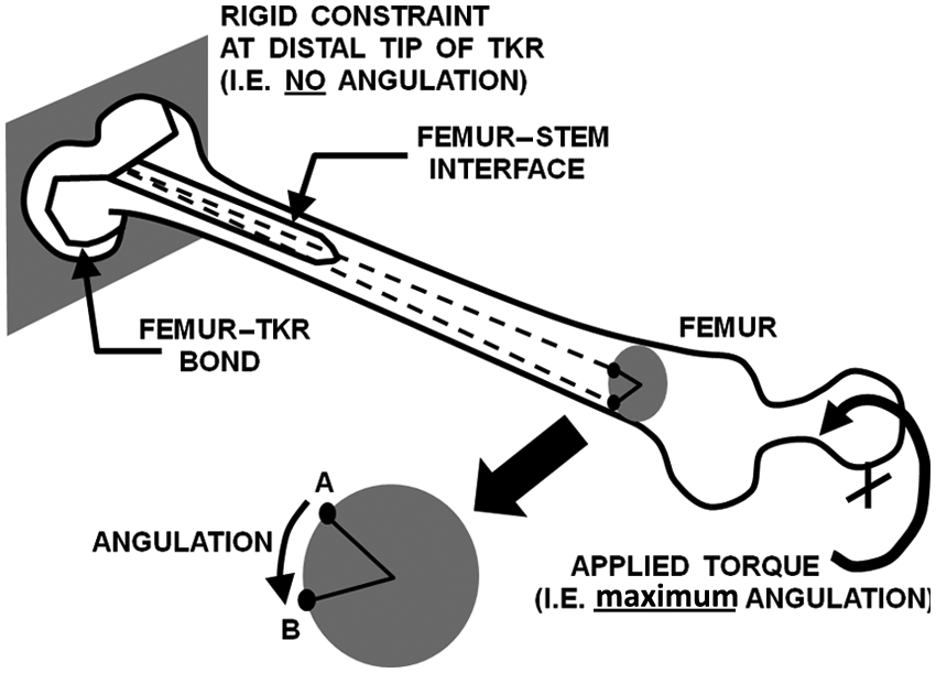
Torque applied to the femoral head creates angulation around the long axis of the femur. The torque creates a smaller angulation at the distal femur–TKR bond (which is maintained by interlocking geometry and, in many cases, bone cement) versus the larger angulation at the more proximal femur–stem interface (which is maintained by friction alone). Typical cross section shows that point A on the surface of the femur rotates to point B during the application of torsion.
It could be argued that an assessment of localized micromotion using radiostereometry and/or load sharing using finite element analysis between the femoral shafts and the stems could provide more useful measures of stem stability.14,16,17 Although this would have provided additional information, it is likely to have corroborated present trends. Moreover, the use of global stiffness and global strength, as employed currently, is an extremely common technique in replicating the behavior of implants during weight-bearing and other activities of daily living.19-22,25–27,44 For instance, the same methodology as used presently was carried out by Ferguson et al. 24 in their similar evaluation of press-fit stems for tumor endoprosthetic reconstruction of the distal femur.
Only five femurs per group were used, as done previously.18–20,24 However, this was too small a population to avoid type II statistical error. Even if statistical differences were found if more femurs per group were used, the clinical ramifications may not be important for all test modes, since all the lateral stiffnesses were within 10% of each other and three of the axial stiffnesses were within 13% of each other. Similarly, only four data points were used to compute the linear correlation R for femur–stem interface area versus stiffness and strength; thus, these results should only be considered preliminary on this specific matter. However, there is precedent in the biomechanics literature for using as few as three to five data points to compute linear correlations.23,45,46
Conclusions
The current aim was to biomechanically compare four types of cementless press-fit stems for revision TKR surgery. There were no statistically significant differences between the stem groups for axial, lateral, or torsional stiffnesses. However, the SSS proved to have a statistically much higher torsional strength than the other stem types. Moreover, virtually all femur–stem interfaces from all four test groups failed by femur ‘spin’ around the long axis of the stem. Although the data indicated no correlation between femur–stem interface area versus stiffness or strength, a parametric study was not done of the influence of stem length, diameter, texture, and the presence of splines.
Footnotes
Appendix 1
Funding
This research received no specific grant from any funding agency in the public, commercial, or not-for-profit sectors. EHS received past payment for consultation and research support from Smith & Nephew. DDRN received past payment for royalties, consultation, and research support from Smith & Nephew and/or DePuy.