
Abstract
Due to the inherent geometric restrictions of a micro gas turbine (MGT) mixed flow compressor design, diffuser design has a major impact on compressor performance and operating range. Vaned diffusers are often preferred to vaneless diffusers in MGT compressor designs due to better efficiency and pressure recovery, albeit at the expense of operating range. A numeric investigation of the effect of a tandem vane crossover diffuser configuration on the performance and operating range of a MGT mixed flow compressor stage is presented. Three baseline test compressors, covering a wide range of design speeds, mass flow rates and meridional exit angles, are designed with a single vane crossover diffuser. For each of the three baseline compressors, the crossover diffuser design is modified to feature various tandem vane configurations. The tangential shift of the second vane row relative to the first row is evaluated. Additionally, relative first and second vane row lengths are evaluated. The performance (efficiency and pressure ratio) and operating range of the modified diffuser configurations are compared to the baseline configurations. It is shown that a 75% second vane row tangential shift configuration displays the best overall performance, regardless of the relative vane length. It is further shown that an appropriate vane length depends on the design requirement.
Introduction
Micro gas turbine (MGT) engines, having their roots in aviation, are becoming increasingly popular in the renewable energy sector. In recent times, significant research is being conducted on converting MGT engine fuel systems to run on hydrogen, allowing carbon free emissions. 1 Aslanidou et al. 2 discussed a theoretical framework for using a fleet of MGTs for domestic heat and power generation. In the aviation sector, MGTs are the powerplant of choice in many unmanned aerial vehicle (UAV) systems, long-range stand-off weapon (SOW) systems and target drones. Regardless of the application or fuel type, the basic working principle and components of a MGT as an air-breathing engine remain unchanged.
In an airborne application, platform manoeuvrability and survivability are important design requirements for a MGT engine. This is achieved by ensuring that an acceptable and optimal balance between size and weight is obtained. Therefore, a need exists for a high-power density propulsion system. MGT engines are attractive options in this regard, due to their high thrust-to-weight ratios. 3 Similarly, the ratio of available-to-required power further influences the overall performance, and by extent the survivability of such platforms. MGT engines traditionally feature centrifugal compressors, due to higher per stage pressure ratios compared to axial flow compressor stages. 4 A disadvantage of such a compressor configuration is the inherent larger frontal area, which consequently leads to higher drag values. 5 Mixed flow compressors provide a real solution in this regard. Smaller frontal areas attributed to the mixed flow configuration has the advantage of reduced drag values, while still achieving acceptable pressure ratios and isentropic efficiencies. 6 Mixed flow compressor configurations therefore provide a design baseline for potentially high performance powerplants that can be used in airborne propulsion systems.
Mixed flow compressors gained their designation on the premise that it is a mixture between a pure centrifugal impeller (meridional exit flow angle of 90°) and a pure axial rotor (meridional exit flow angle of 0°). A reduced impeller exit meridional angle ( Impeller meridional exit angle (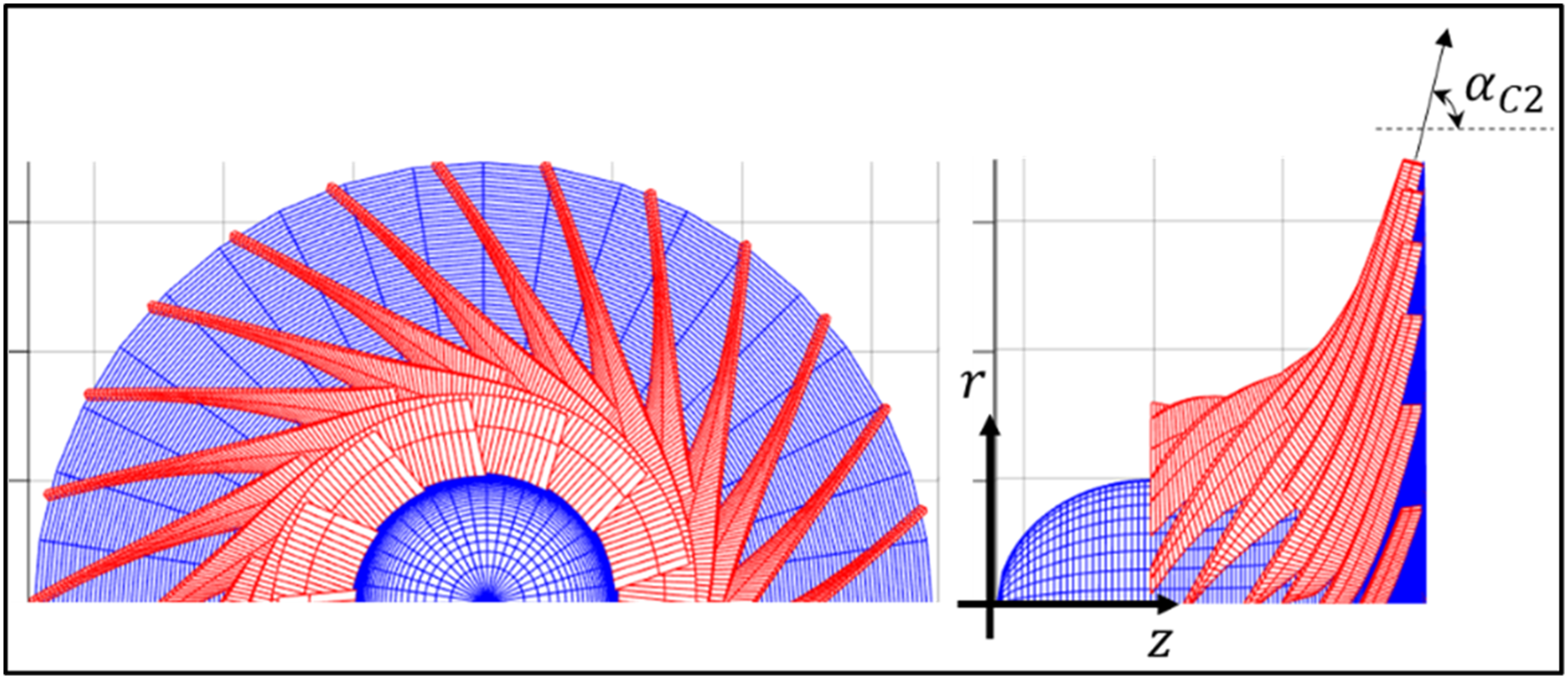
In MGT engines, overall compressor performance is largely dictated by diffuser performance, which therefore requires careful design. The work done by an impeller to achieve satisfactory pressure ratios and efficiencies can be counteracted by poor diffuser performance. Compared to vaneless diffusers, vaned diffusers provide higher efficiencies.
9
In MGT applications, therefore, vaned diffusers are preferred to vaneless configurations. Diffuser design is particularly challenging in a MGT engine setup, where strict geometric limitations are enforced. Crossover diffuser configurations are well suited for use in such applications and provide better diffusion performance than similar conventional diffuser configurations.
10
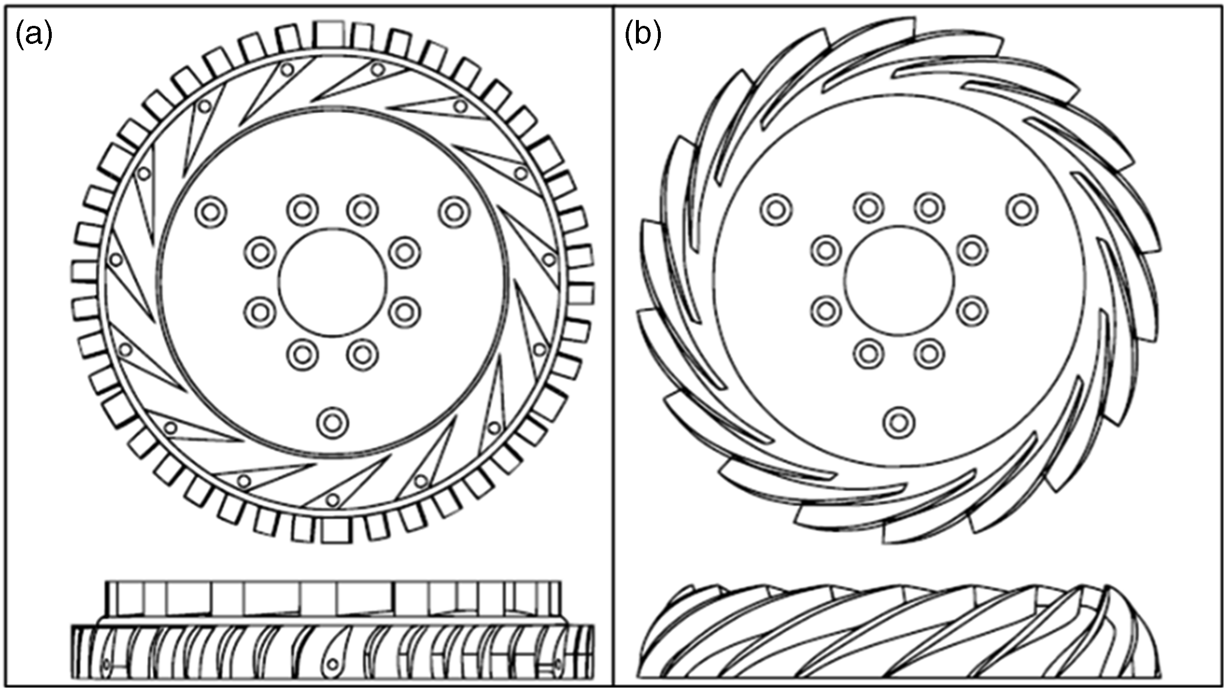
Conventional diffusers typically comprise a wedge-type radial vane, a vaneless bend and de-swirler vanes (see Figure 2(a)). These are typically prone to flow breakaway and efficiency losses in the vaneless bend section.
10
The inherent continuous flow passages of crossover diffusers allow for gradual diffusion and flow turning, even when the passages are geometrically constrained (see Figure 2(b)). (a) Conventional diffuser configuration, (b) Crossover diffuser configuration.
11
In MGT engines, vaned diffusers are typically the limiting component in terms of compressor performance. Additionally, the diffuser also dictate the compressor operating range, with both the onset of stall and choke occurring in the vaned diffuser section of the compressor. Due to their long channel pathways, a limited operating range is particularly common in crossover diffuser configurations. The situation is intensified by the higher mass flow rates achieved by mixed flow designs. Careful diffuser design is therefore crucial to ensure proper compressor operation.
The long flow passages of crossover diffusers have a detrimental effect on operating range due to boundary layer growth. A pressure gradient forms on the suction side of the diffuser vane close to the leading-edge. This pressure gradient induces a secondary flow from hub to shroud on the suction side, which leads to separation towards the rear of the diffuser passage.
12
The longer the passage, the harsher the effect of the growing boundary layer on stage performance, especially at off-design points. The boundary layer growth in the flow passage can be controlled by introducing a tandem vane configuration.
13
The slot created by the tandem vanes (see Figure 3) allows the boundary layer to be re-energised, better controlling the boundary layer at various operating points and therefore the overall operating range. Tandem vane crossover diffuser schematic.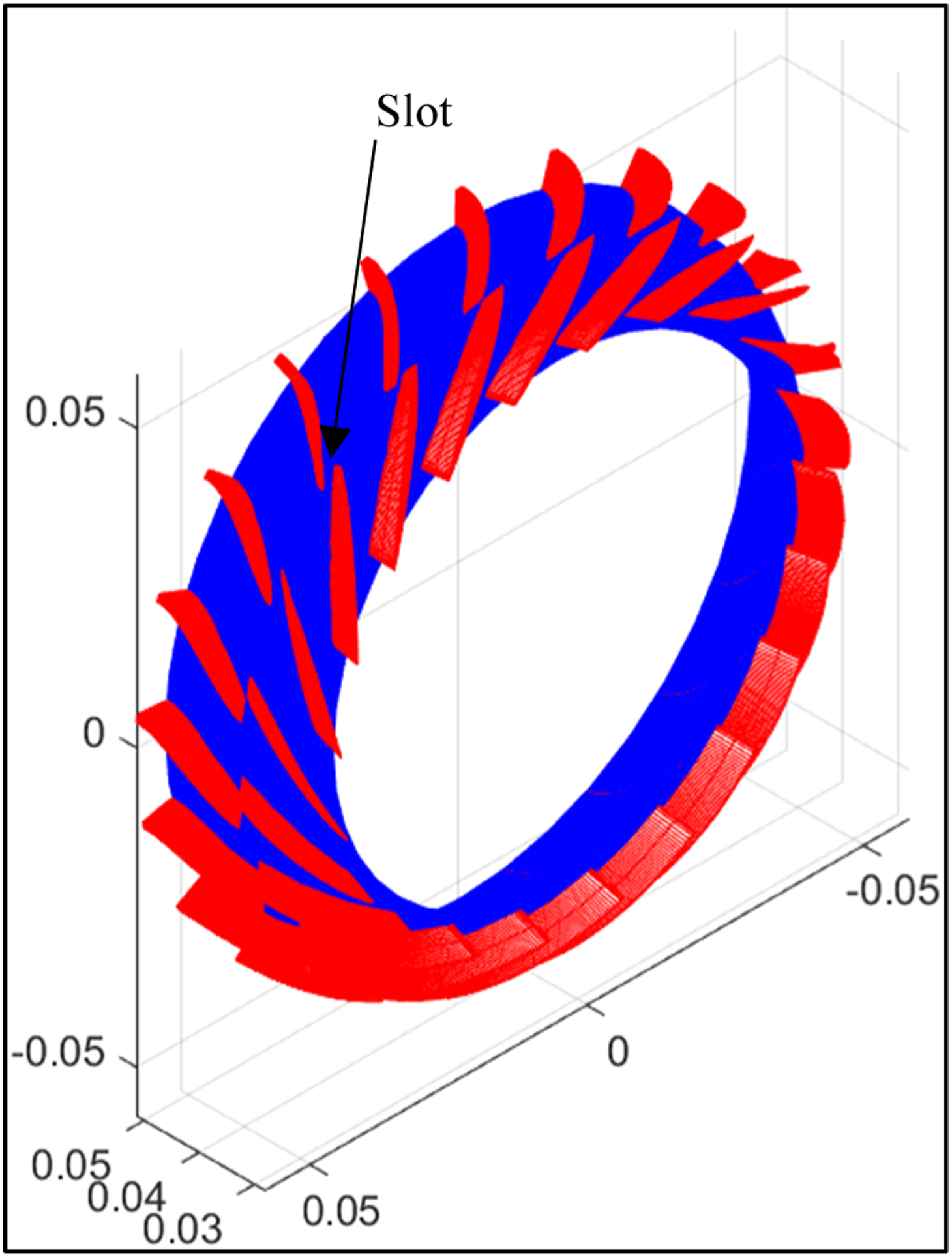
A multi-row tandem vaned diffuser can be designed with two, three or even more rows. When two rows are present, the first row is primarily responsible for flow stabilisation and the subsequent row for de-swirl and diffusion. In a three-row configuration, the first row is responsible for flow stabilisation, the second row for diffusion and the third row for flow axial re-alignment (de-swirl). 14 The choice of number of rows are determined by overall design requirements, geometric parameters and ease of manufacture.
The effect of a dual tandem vane crossover diffuser configuration on the performance of a MGT mixed flow compressor is numerically evaluated in this study. To this end, three baseline test compressors featuring a single vane crossover diffuser are designed. For each of the baseline compressors, the performance of tandem vaned modified diffuser configurations is compared to the baseline performance. Two primary diffuser modification sets are evaluated, namely, relative second row tangential shift and relative vane length.
The current study forms part of a larger study evaluating the effect of various crossover diffuser configurations on the performance of the compressor stage of a MGT engine. A similar evaluation methodology and baseline compressor set are therefore used.
Baseline test compressor design and CFD validation
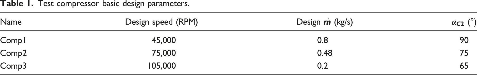
The concept compressors evaluated in this study are designed using the 1D Application (App) as develped by Van Eck et al. 15 The 1D App is an in-house developed MATLAB™ based mixed flow compressor design tool. The code is based on one dimensional mean line and loss model theory. The layout and working of the 1D App is detailed in Van Eck et al. 15 For the purpose of this study, three baseline test compressors (Comp1, Comp2 and Comp3) are designed. Each of these features a splitter blade impeller and single vane crossover diffuser. The baseline compressor performances serve as datum to compare the modified diffuser configurations against. To ensure comparability between the baseline compressors and modified diffuser configurations, the impeller sections and meridional shape of the diffuser sections are kept unchanged.
Test compressor basic design parameters.
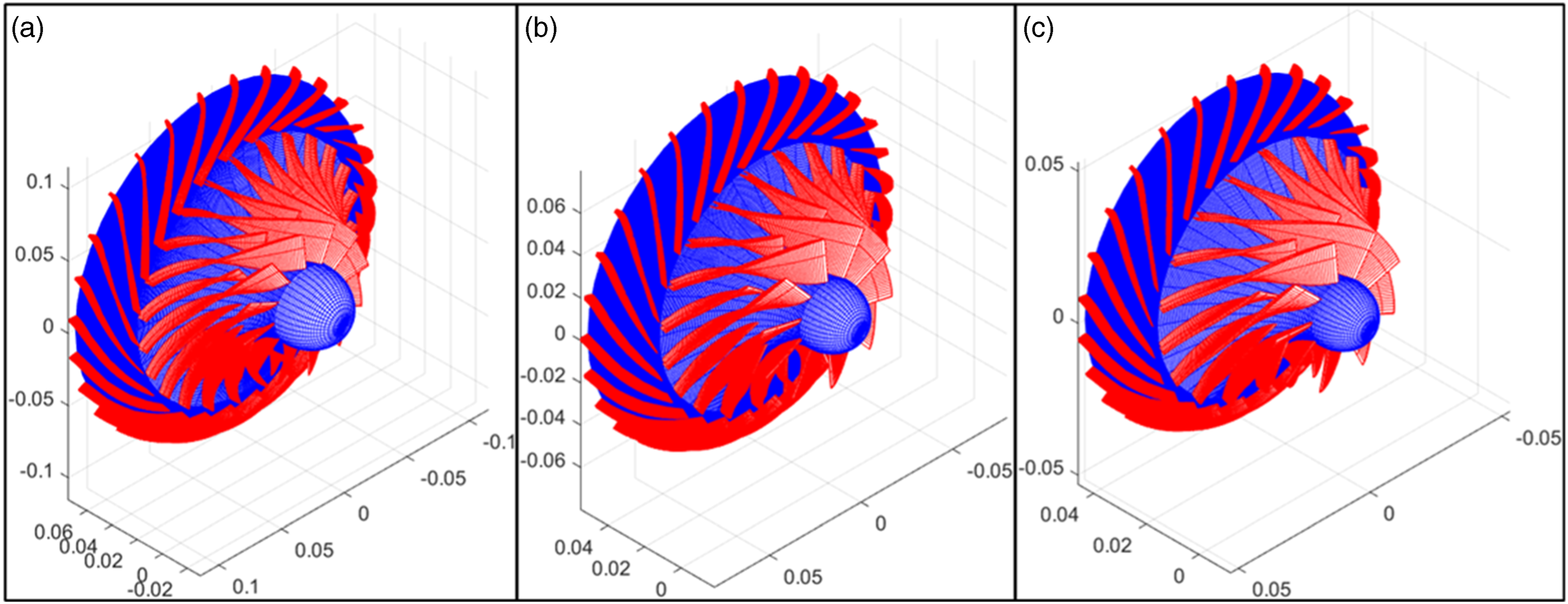
Meridional views and 3D schematics of the three test compressors are provided in Figures 4 and 5. Test compressor meridional views – (a) Comp1. (b) Comp2. (c) Comp3. Test compressor 3D schematics – (a) Comp1. (b) Comp2. (c) Comp3.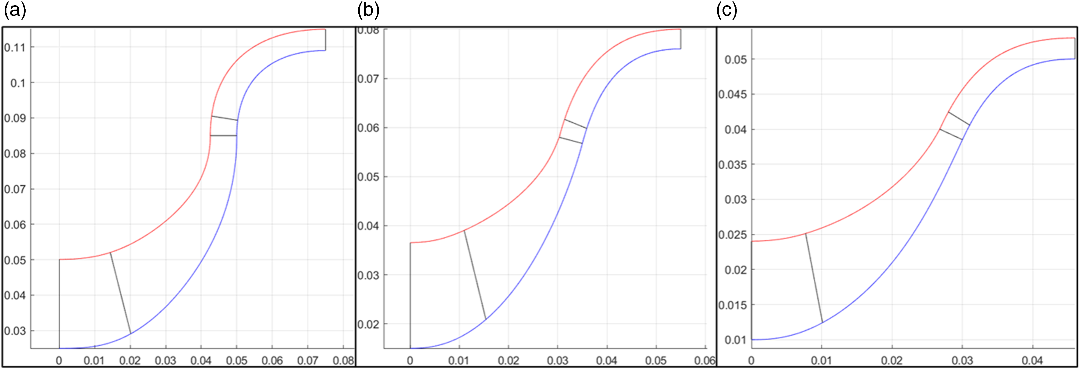
Medium (111) versus fine (000) mesh comparison – Comp3.
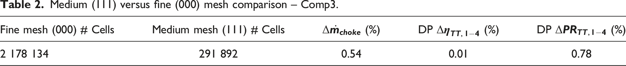
These observed minor differences between the fine and medium grid levels are deemed insignificant for the purpose of this study. In this study, the Spalart–Allmaras turbulence model is used, as recommended by Numeca™ for centrifugal compressors. The model is a one-equation model and provides economical computations in boundary layers, especially for external aerodynamic applications where adverse pressure gradients are encountered. 16 For the Spalart–Allmaras turbulence model, proper boundary layer simulation is achieved when the achieved 𝑦+ values remain below 10. For Comp3, the 111 grid level simulation achieved a maximum 𝑦+ value of 8. This result further justifies the use and accuracy of the 111 grid level.
For the purpose of this study, air as a calorically perfect gas is selected as the working fluid. Additionally, steady state flow conditions are selected. As explained above, the 111 grid level is selected as the ‘Current grid level’ of the Numerical Model, with the default Courant–Friedrich–Levy (CFL) number of 3 being kept unchanged. This value was found to provide good convergence results and no CFL number alterations were required. Under the ‘Control Variables’, the Solver Precision was set to ‘Single’. This setting is recommended by Numeca™ for the current setup, 17 which provided sufficiently accurate results. The setup of the CFD in this study has been evaluated and verified by various previous studies on similar compressor configurations.10,18
To ensure dynamic comparability, the inlet boundary conditions are set to ‘Total Quantities Imposed’ and are kept constant at standard atmospheric conditions, namely, 101,325 Pa and 288 K. The ‘Velocity direction’ selection is made, with the flow being purely axial approaching the inlet. The various operating curve points are determined by altering the mass flow rate [in kg/s] as an outlet boundary condition. This is done by selecting ‘Mass Flow Imposed’ at the ‘OUTLET’ boundary. The only exception here is the choke point, which is determined by setting the outlet boundary condition to a static pressure well below the lowest achievable exit pressure to induce choke. For both ‘Mass Flow Imposed’ and ‘Static Pressure Imposed’ outlet conditions, ‘Backflow Control’ is selected. This allows the software to better control the exit stagnation temperature distribution, especially when exit flow segments re-enter through the outlet boundary. 17 All other simulation flow settings are set as presented by Van Eck et al. 15
In a CFD environment, the identification of a true stall point is often tricky, especially when steady state flow conditions are selected (as is the case for the current study). Part of the purpose of this study is to evaluate the steady operating range of a MGT mixed flow compressor stage fitted with a tandem vaned crossover diffuser. To this end, a conservative stall-point determination method is selected, which is based on the instability criteria of Japikse and Baines
19
: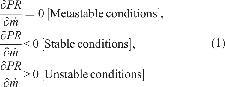
The ‘stall’ point used in this study is therefore not a true stall point, but a stable operating range limit near stall. This approach is selected to ensure that the resulting operating ranges are feasible and conservative from a modelling point-of-view.
To evaluate the effect of a tandem vaned crossover diffuser, the various diffuser modified compressors are evaluated and compared to the baseline compressor performance. To ensure comparability between the baseline single vane crossover diffusers and the tandem vane modified diffusers, the baseline diffuser meridional vane shape, maximum thickness and vane trailing-edge thickness are maintained. In the 1D App, a single diffuser vane is designed around a mean camber line around which a thickness distribution is defined.
20
Defining the dimensionless parameter 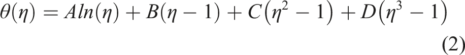
The camber line is defined in the form of an angular distribution. It provides a vector of the tangential displacement between consecutive meridional points. In the case of the 1D App, the diffuser vaned section is designed along quasi normals.
15
With the 2D position of the diffuser vane leading-edge known, each consecutive point can be determined using the camber line distribution. The values of 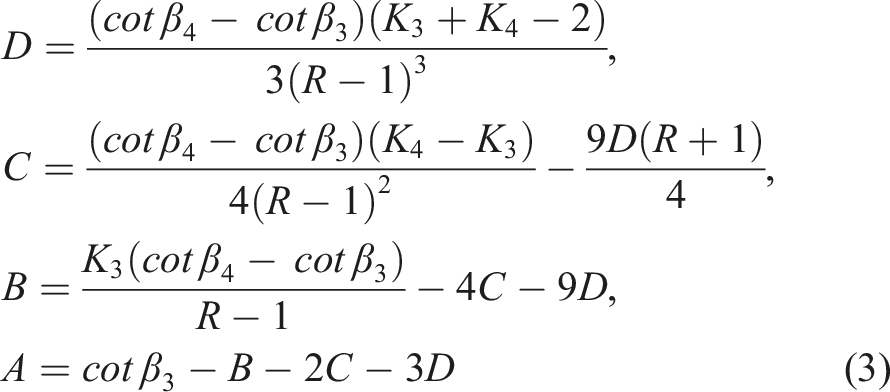
For the design of a tandem vane configuration, the mean camber line is still designed for the entire vaned section. Each vane is designed separately around the mean camber line based on its own thickness distribution. The second vane row is merely shifted tangentially based on the user defined relative tangential shift parameter. Figure 6 provides a schematic of the 2D transformation plot for Comp2 and Comp2_50-75 (naming convention explained later). The black dotted line indicates the mean camber line for the entire vaned section around which both front and rear vanes are designed. If the second vane row has been defined with a relative tangential shift, it maintains its shape and is merely shifted in the desired direction. Diffuser 2D transformation plot – (a) Comp2. (b) Comp2_50-75.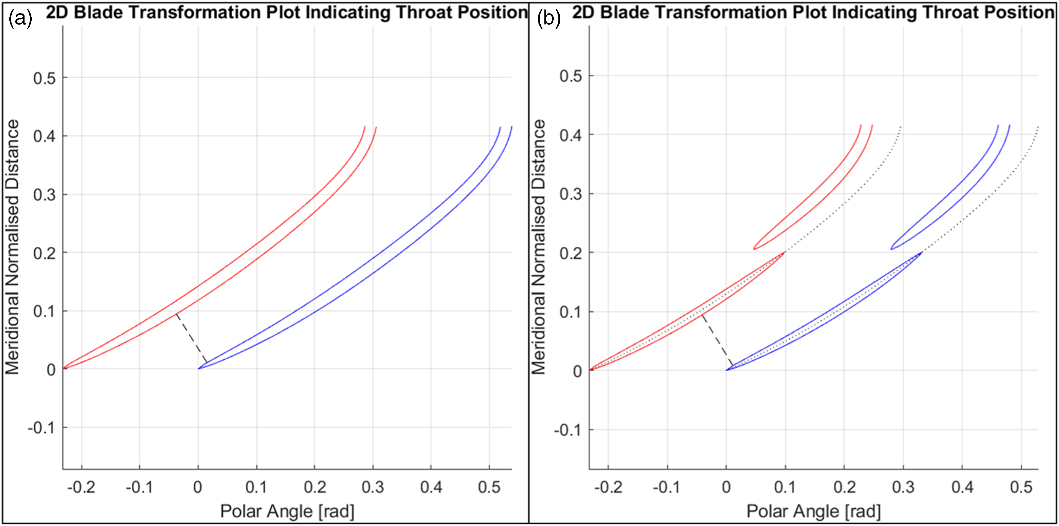
Tangential shift evaluation
The effect of rear vane row tangential shift of a tandem vane crossover diffuser is evaluated. Relative tangential shift is defined as the ratio of the tangential distance between the leading-edge of a second vane and the trailing-edge of the associated first vane compared to the distance between consecutive first vane row trailing-edges ( Diffuser meridional view: Tandem vane tangential shift Definition.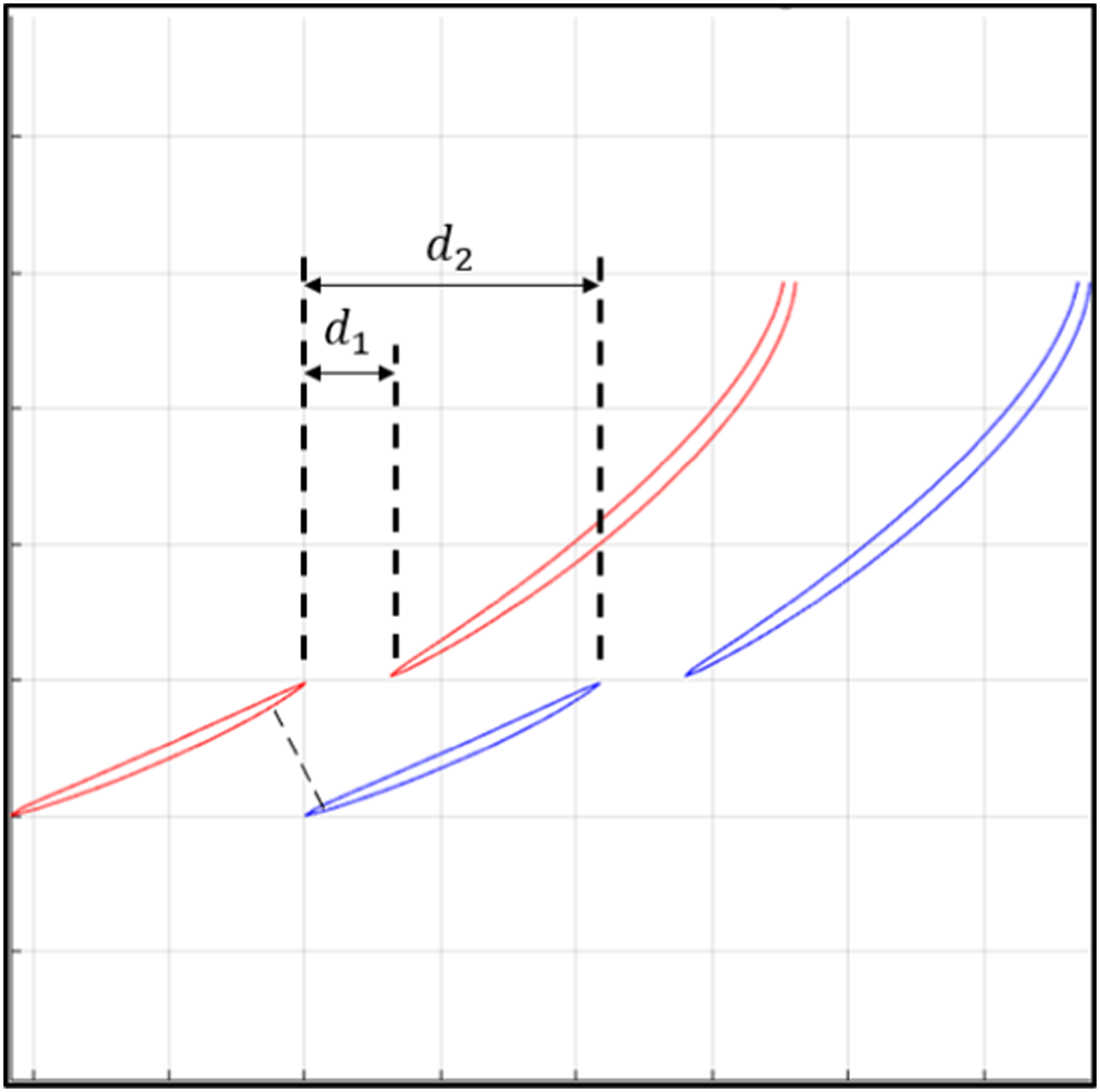
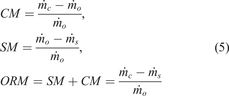
To distinguish between the various diffuser modifications made to the baseline compressors, the following naming convention is implemented. CompZ_
It is important to note that a difference exists between the naming convention and practical implementation for tangential shift values above 50%. Geometrically, a tangential shift of 75% is the same as −25%. This distinction is however important, as it places the associated rear vane geometrically closer to the associated front vane. The closer proximity simplifies mesh creation. Therefore, a 75% tangential shift is always defined as −25% in the 1D App to ensure that the geometry file is set up accordingly for export to AutoGrid5™.
For all the tangential shift configurations in this evaluation, a meridional axial gap (between the front and rear diffuser vane set) of 1% is selected (see Figure 8). This selection is based on the findings of Qiushi et al.,
21
who recommended a best performing axial gap size of zero. In this study, four tangential shift configurations are evaluated, namely, 0%, 25%, 50% and 75% (see Figure 8). To ensure a gap is present at the 0% tangential shift position, a small axial gap size of 1% is therefore selected. Tangential shift evaluation positions – 30-xx.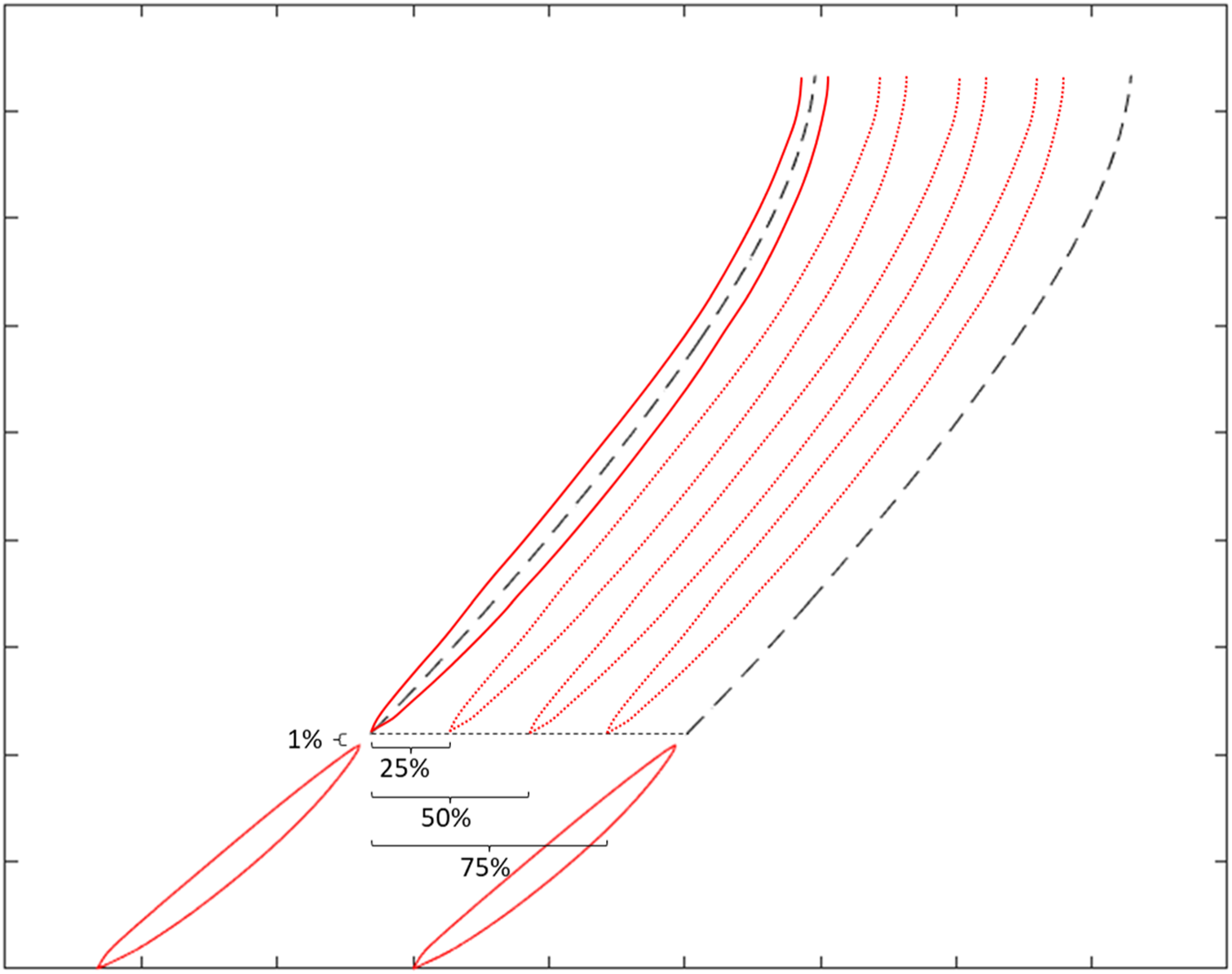
In this section, both the 30-xx and 70-xx configurations are evaluated. These are discussed separately below.
30-xx evaluation
The selection of 30-xx ensures that the front vane has a solidity of less than 1, which implies a low solidity front vane row. Diffuser vane solidity (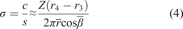
30-xx tandem vane tangential shift performance results – Comp2.
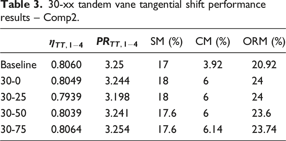
From Table 3, it is evident that in terms of choke margin, all the modified configurations provide similar performance, displaying an increased choke margin compared to the baseline compressor. This is expected, due to the first diffuser vane being a low solidity vane, which implies no geometric throat in the first vane row.
23
This leads to the assumption that the geometric throat has moved to between the rear vanes. This is however not an accurate assumption, as indicated in Figure 9. Comp2_30-xx choke visualisation at 50% span – (a) baseline, (b) 30-0, (c) 30-25, (d) 30-50, and (e) 30-75.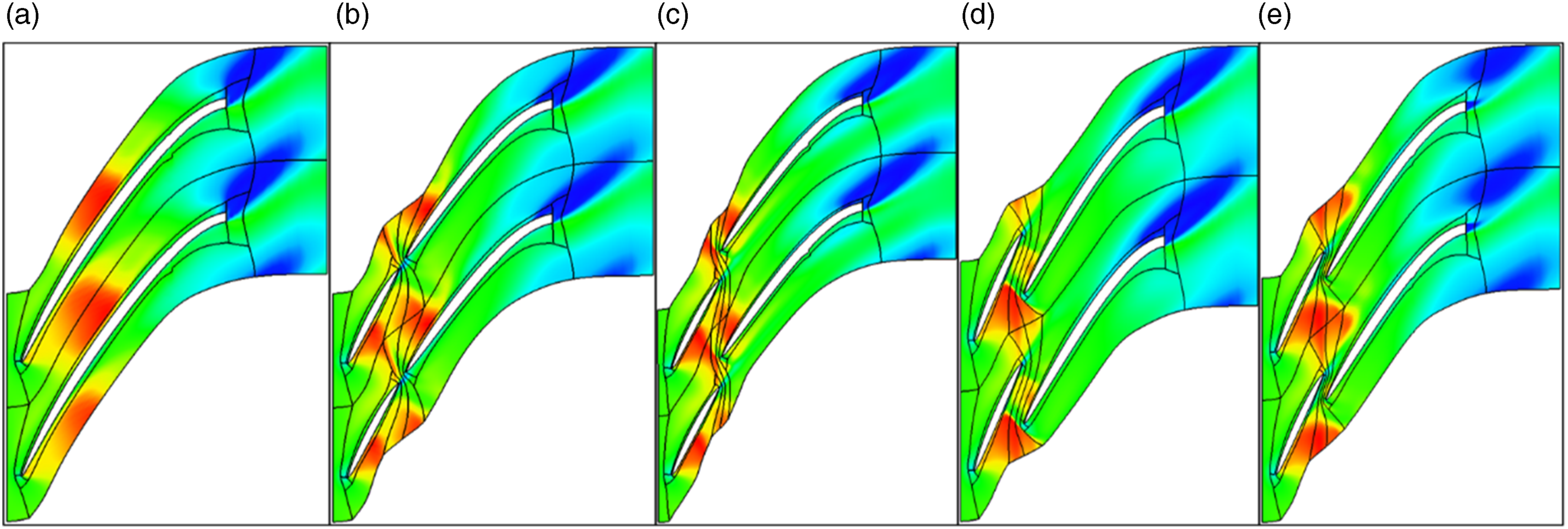
From Figure 9, it is evident that a shock system still forms around the rear of the front vane row. Two distinct shocks are observed for the 30-0, 30-25 and 30-50 configuration. A single shock is observed for the 30-75 configuration, which could explain its slightly increased choke margin compared to the other modified configurations. For all the modified configurations, the initial shock front negotiated by the incoming diffuser flow is the line between the trailing-edge of vane 1 (suction side) and a point just behind the leading-edge of the next vane 1 (pressure side) (see Figure 10). This distance is the same for all the modified configurations, which explains the near exact choke margins. This distance is also larger than the throat blade-to-blade distance for the baseline configuration, which explains the increased choke margin of the modified configurations compared to the baseline configuration. First shock front – Comp2_30-75.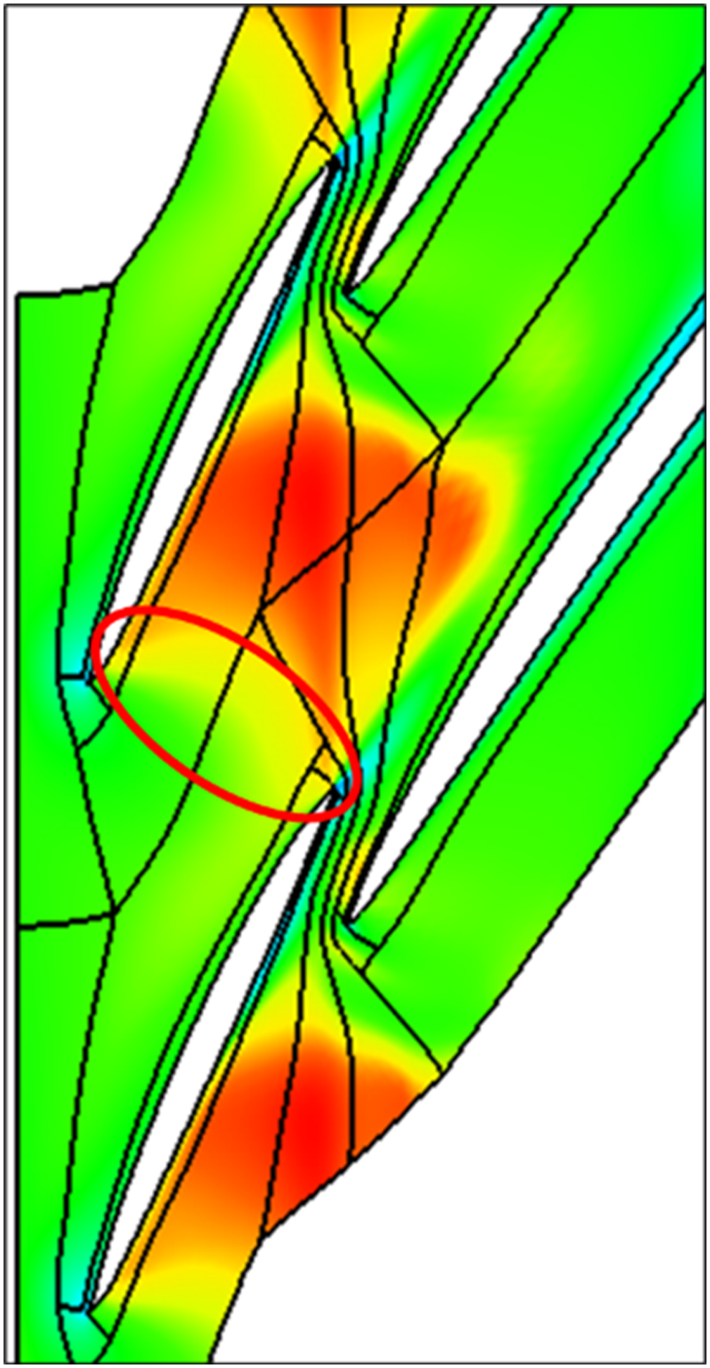
In terms of stall, all the modified configurations display a small increase in stall margin compared to the baseline configuration (see Table 3). This slight increase in stall margin is attributed to the slot (created between the front and rear vane) disrupting the formation of the leading-edge spanwise separation area as stall is approached. In terms of design point performance, it is only the 30-75 configuration which provides slightly better efficiency and pressure ratio results when compared to the baseline configuration.
Exit tangential velocity comparisons – Comp2_30_xx.
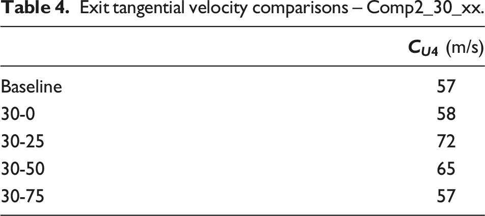
The exit tangential velocity increases for all the configurations, except the 30-75 configuration. This is attributed to the placement of the first vane in closer proximity to the suction side of the associated second vane. The effect is an accelerated flow through the created slot, which re-energises the boundary layer, delaying separation and reducing the mean tangential flow. The 30-75 configuration therefore performs the best in terms of exit tangential velocity, compared to the baseline configuration.
Due to manufacturing considerations, the 1D App is coded to ensure that the maximum diffuser vane thickness parameter remain at or above a minimum value of 1 mm. In geometrically smaller compressors (e.g. Comp3), this restriction leads to a relatively thick low solidity front vane. Compared to the baseline configuration, a reduced choke margin is consequently observed for the Comp3_30-xx configurations. The choke advantage of the low solidity front vane is therefore nullified for the Comp3_30-xx configuration due to manufacturing considerations. Comp3 is therefore not used for the 30-xx comparison.
30-xx tandem vane tangential shift performance results – Comp1.
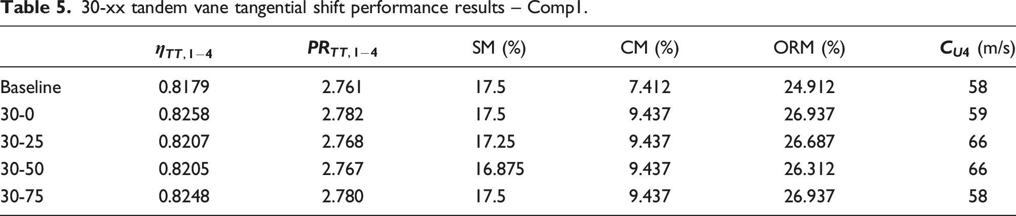
From Table 5, it is evident that for Comp1, the 30-0 configuration performs marginally better than the 30-75 configuration in most aspects. These two configurations do however both perform better than the 30-25 and 30-50 configuration in all aspects. This result indicates that an optimum solution for Comp1 might be at a relative tangential shift angle of between 75% (−25%) and 0%. In general therefore, the 30-xx configuration does not provide a substantial increase in design point and stall margin performance over the baseline configuration. The 30-xx configuration does however provide a marked increase in choke margin, with an associated increase in operating range margin. The Comp1_30-75 configuration displays a 27.3% (relative) increase in choke margin compared to the baseline Comp1, while Comp2_30-75 displays a choke margin increase of 56.6% (relative) to Comp2. To visualise the operating range increase, the performance curves of Comp2 versus Comp2_30-75 are displayed in Figure 11. Comp2 and Comp2_30-75 comparative performance curves.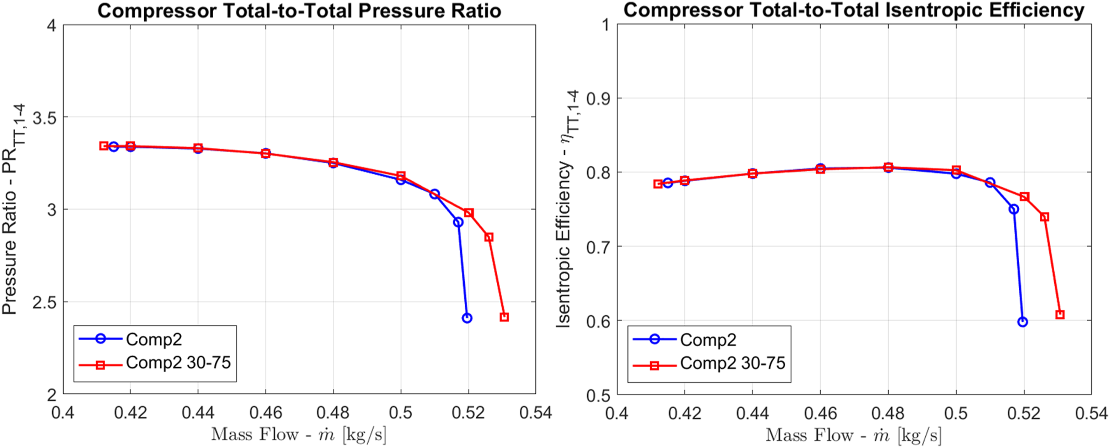
Based on choke margin, design point performance and exit tangential velocity for both Comp1 and Comp2, the 30-75 configuration is recommended for the 30-xx evaluation.
70-xx evaluation
70-xx tandem vane tangential shift performance results – Comp2.
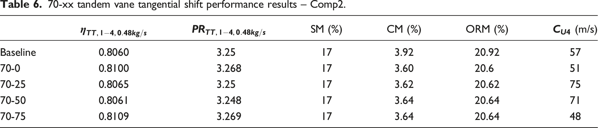
From Table 6, it is evident that the choke margin for all the 70-xx configurations is reduced compared to the baseline configuration. This is due to the decrease in throat area attributed to the shorter front vane compared to the baseline configuration. The maximum thickness of the front vane is the same as the maximum vane thickness of the baseline configuration. In the shorter front vane of the 70-xx configuration, the point of maximum thickness is meridionally closer to the front vane leading-edge, hence the slightly reduced throat area. The small differences in choke margin between the various 70-xx configurations are of no consequence. The choke margin for these is for all practical purposes the same due to the front vane design being identical for all of them (see Figure 12). Comp2_70-xx choke visualisation at 50% span – (a) 70-0, (b) 70-25, (c) 70-50, and (d) 70-75.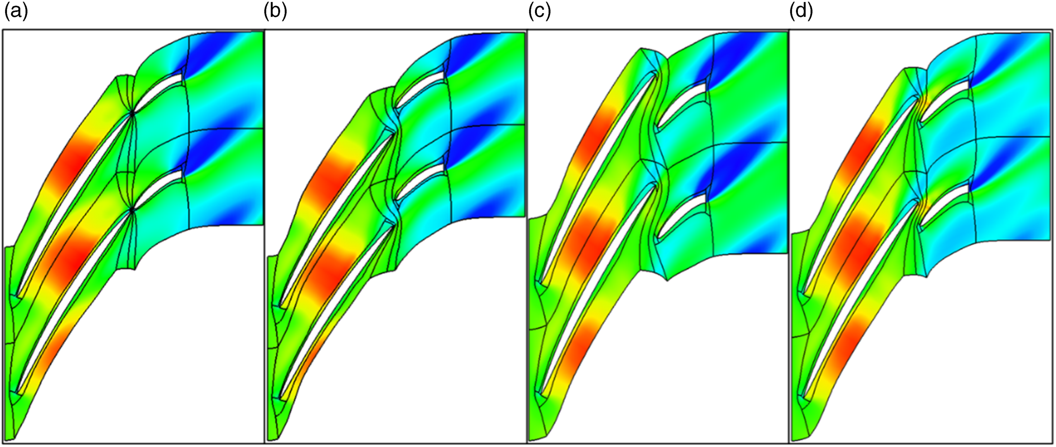
The stall margin is not affected by the 70-xx configuration (see Table 6). Stall is affected by the front leading-edge vane angle and the proximity of the front vane leading-edge to the impeller exit (recirculation area). These parameters remain unchanged between the baseline configuration and the 70-xx configuration, hence no stall margin differences.
From Table 6, it is evident that the 70-75 configuration provides the best design point performance for both efficiency and pressure ratio. This result agrees with the 30-xx evaluation, which also indicates that the 30-75 is the better performing configuration. It is also evident that the 70-75 configuration provides the lowest exit tangential velocity component, even lower than the baseline configuration. This is due to the accelerated flow over the suction side of the rear vane, re-aligning the flow towards the axial direction (see Figure 13). Comp2_70-75 exit flow velocity vectors.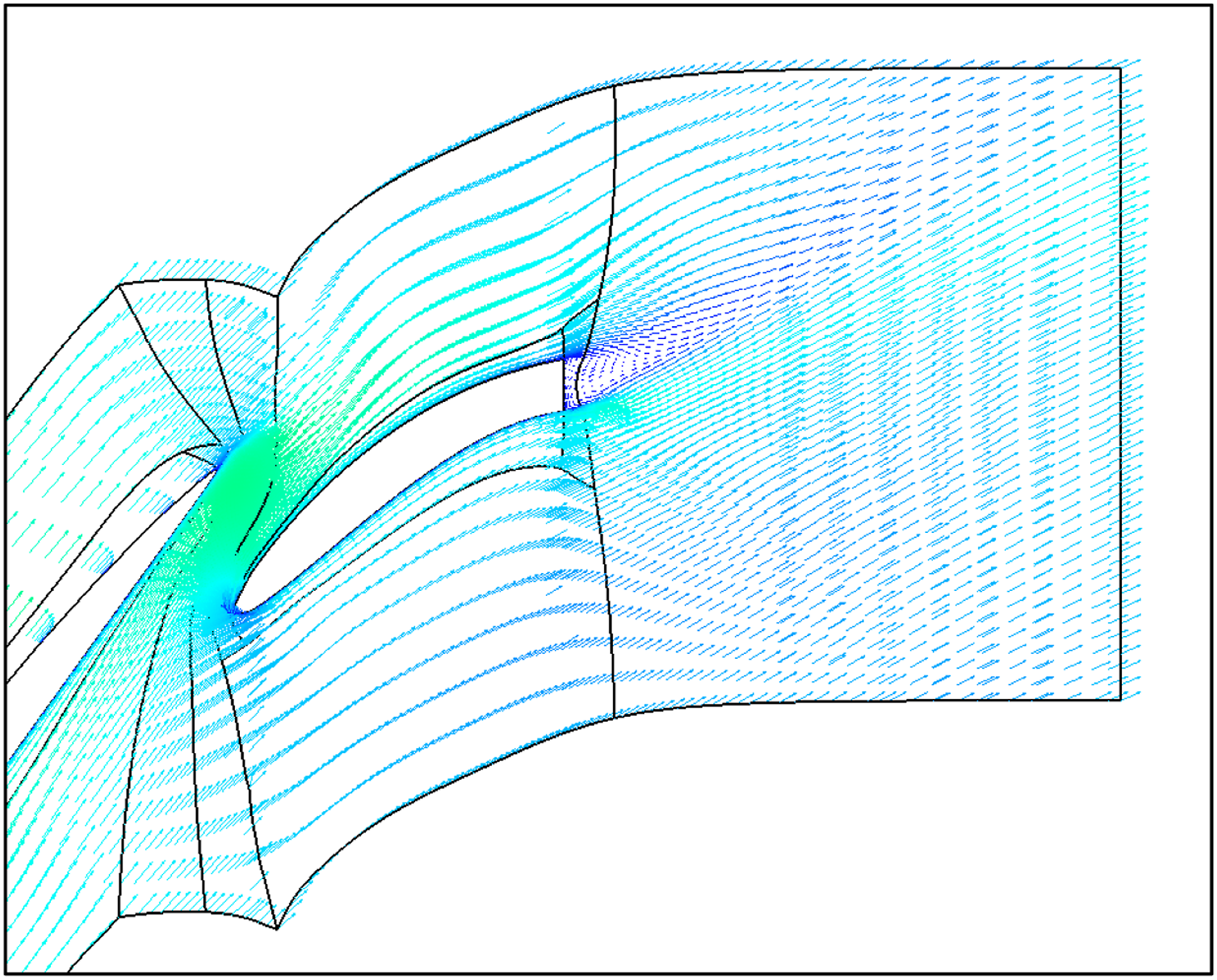
The result obtained here is positive for the designer of a MGT mixed flow compressor stage. Diffuser vane exit angle has a marked influence on the diffuser vane loading parameter (
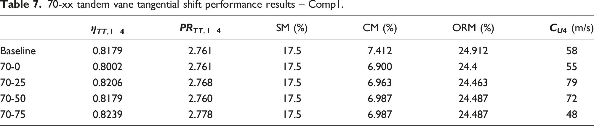
70-xx tandem vane tangential shift performance results – Comp1.
70-xx tandem vane tangential shift performance results – Comp3.
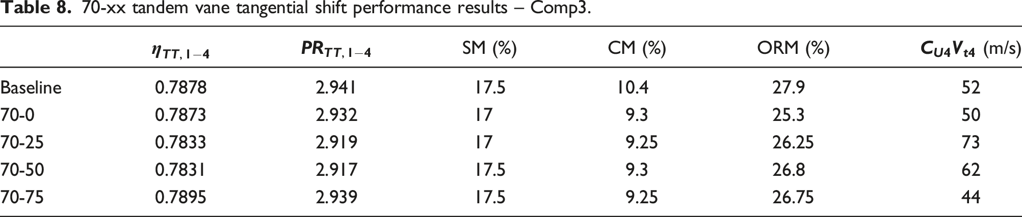
Tables 7 and 8 show similar stall margin and choke margin behaviour for Comp1 and Comp3 when compared to Comp2. The 70-75 configuration provides the best design point performance and lowest exit tangential velocity, which further agrees with the findings of the Comp2_70-xx evaluation.
Based on improved design point performance and reduced exit tangential velocity, the 70-75 configuration is the best performing configuration of the 70-xx evaluation. This finding agrees with that of the 30-xx evaluation. It is therefore concluded that a 75% rear vane tangential shift is the best configuration, regardless of vane length. These results correspond well with the findings of Qiushi et al. 21 and Oh et al. 24
Relative vane length evaluation
yy-75 tandem vane axial length performance results – Comp2.
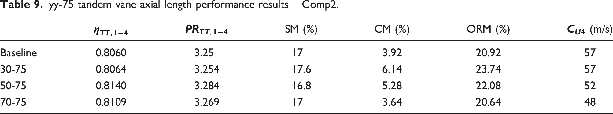
From Table 9, it is evident that choke margin is directly affected by the relative front vane length. The increased choke margin of the 30-75 configuration is attributed to the low solidity front vane, as discussed earlier. The increased choke margin of the 50-75 configuration is attributed to the lower maximum thickness of the front vane compared to the baseline configuration. The reduced choke margin of the 70-75 configuration is attributed to the front vane point of maximum thickness being meridionally closer to the front vane leading-edge, as explained earlier. For a yy-75 configuration, stall margin is not markedly affected compared to the baseline configuration. This is due to the front vane leading-edge parameters and position remaining largely the same as the baseline configuration. The slight increase in stall margin for the 30-75 configuration is attributed to the forward slot disrupting the formation of the leading-edge spanwise separation area as stall is approached.
From Table 9, it is evident that the 50-75 configuration provides the best design point performance values. Japikse 14 theorises that in a two vaned tandem configuration, the front vane row is primarily responsible for flow stabilisation and the rear row for diffusion and axial re-alignment. The relationship between diffusion and flow re-alignment attributed to the rear vane is affected by the relative length of the rear vane. Similarly, a longer front vane would also contribute to diffusion in conjunction with flow stabilisation. In the 50-75 configuration, a superior diffusion configuration is reached when compared to the other two configurations, hence the higher performance figures.
As expected, the 70-75 configuration performs the best in terms of exit tangential velocity. The reason for this is as per the explanation in the 70-xx evaluation section. Due to the similarity between the various test compressors in the 30-xx and 70-xx evaluations, only Comp2 is used for the vane length evaluation.
No outright best configuration can be recommended for the vane length evaluation. A vane length recommendation is dependent on the design requirement. A requirement for a larger choke margin will necessitate a shorter (preferably low solidity) front vane. A requirement for a reduced exit tangential velocity will necessitate a shorter rear vane.
Conclusion
In this study, various tandem vaned crossover diffuser configuration modifications are evaluated. Relative tangential shift is evaluated for both 30-xx and 70-xx configurations. The 30-xx configuration results in a low solidity front vane row for all three test compressors used in the evaluation. The effect is an increase in choke margin compared to the baseline configuration. The Comp2_30-75 configuration provides a 56.6% (relative) increase in choke margin compared to the baseline configuration. Stall margin and design point performance are not markedly influenced by the 30-xx configuration. The 30-75 configuration is the only 30-xx configuration which provides better or similar exit tangential velocity values compared to the baseline configurations.
For the 70-xx configuration, a slight decrease in choke margin for all the modified configurations is observed when compared to the baseline configurations. This is attributed to the front vane reaching the point of maximum thickness at a decreased meridional distance behind the leading-edge compared to the baseline configuration. Again, design point performance and stall margin are not markedly influenced by the 70-xx configuration compared to the baseline configuration. The 70-75 configuration provides noticeably reduced exit tangential velocity compared to the baseline configuration, while the remaining 70-xx configurations display an increased exit tangential velocity. The Comp2_70-75 displays a 15.8% reduction in exit tangential velocity.
A tandem vane length evaluation is conducted by varying the front vane length relative to the total diffuser vaned length. Three configurations are evaluated, namely, 30-75, 50-75 and 70-75. The evaluation shows that choke margin is dependent on the front vane length, with a shorter vane length displaying an increased choke margin. This is however based on the solidity of the front vane row and the designed maximum thickness of the front vane compared to the baseline configuration maximum vane thickness. The 70-75 configuration displays the lowest exit tangential velocity. The conclusion is therefore that the choice of appropriate tandem vane length for a crossover diffuser is dependent on the design requirement.
Previous studies have evaluated and showed the advantages of single vaned crossover diffusers. These include superior diffusion performance compared to legacy diffusers, while still ensuring gradual flow re-alignment, stabilisation and de-swirl by means of a single vaned configuration. The primary disadvantage of the single vaned crossover configuration is however a reduced operating range due to the boundary layer development in the longer flow passages. The relatively high vane number needed to achieve proper diffusion further leads to smaller diffuser throat areas with associated choke limitations. This study highlights the advantages of a tandem vane crossover diffuser configuration. While gradual flow re-alignment, stabilisation and de-swirl are still achieved, additional advantages of the tandem configuration include a wider operating range and reduced exit tangential velocity.
Footnotes
Declaration of conflicting interests
The author(s) declared no potential conflicts of interest with respect to the research, authorship, and/or publication of this article.
Funding
The author(s) received no financial support for the research, authorship, and/or publication of this article.