
Abstract
This study presents a new concept of self-driven pulsed jet flow control on a compressor stator blade. This passive unsteady flow control method has the advantage that neither external flow nor electrical source is needed. This study’s preliminary proof-of-concept study on a low-speed compressor stator blade is performed using numerical simulation. When the pulsed jet frequency is 100 Hz, the optimum control performance and control efficiency are reached, and the total pressure loss coefficient is reduced by 8.9%. As the valve’s rotational speed increases, the pulsed jet’s momentum coefficient decreases gradually. The analysis of the unsteady characteristics of the self-driven pulsed jet shows that the jet velocity is close to a periodic square wave signal, and the typical reduced jet velocity ranges from approximately 0.15 to 0.8. Moreover, the time-averaged driving torque on the valve depends on the rotational speed and is relevant to the self-starting and self-driven characteristics of this passive flow control method. Under different bearing resistance torque, the self-driven valve behaves differently in three cases that can self-start and be self-driven, cannot self-start but can be self-driven, and cannot self-start nor be self-driven.
Introduction
Nowadays, the development trend of aero-engines is to pursue a higher thrust-weight ratio and lower fuel consumption. To realize this goal, state-of-the-art compressors are designed to be highly loaded while maintaining high efficiency and stall margin. However, highly loaded compressors will likely encounter flow separation because the flow is under a high adverse pressure gradient. Compared with the flow attached over the compressor stator blade, flow separation tends to reduce the pressure ratio, isentropic efficiency, and stall margin of the compressor. Thus, mitigating the unwanted effects of flow separation is necessary and introducing flow control is one effective way.
Steady or unsteady flow control techniques unusually realize flow control on flow separation. Unlike steady flow control methods, such as steady blowing or suction, unsteady flow control methods use periodic excitation that exploits natural flow instability. 1 Moreover, unsteady flow control methods were shown to be much more effective than traditional steady flow control methods and could attain a saving of up to two orders of magnitude in the momentum coefficient required to achieve a similar gain in performance. 2 Effectiveness and efficiency drive unsteady flow control to develop rapidly in the last decade.
Unsteady flow control is usually realized by active flow control (AFC). In AFC, actuators are used to convert a controllable electrical signal to a desired physical quantity to modify a flow. 3 The field of AFC has witnessed explosive growth in the variety of actuators, and popular actuator types can be typically classified (based on function) as fluidic, moving surface and plasma. 3 Fluidic actuators use fluid injection or suction, including synthetic jet,4,5 pulsed jet, 6 pulsed suction, 7 and fluidic oscillators. 8 Moving surface actuators mainly include wall oscillation, 9 oscillating wire, 10 rotating surfaces, 11 and traveling wave walls. 12 The last class, plasma actuators, includes single dielectric barrier discharge (SDBD) plasma, 13 localized-arc-filament plasma actuators (LAFPA), 14 and plasma synthetic jet actuators (PSJA).15,16 Active unsteady flow control has the advantage in that it can adjust control parameters such as frequency and momentum injection, making active unsteady flow control function well at off-design conditions and suitable for open-loop and closed-loop (feedback) control.
However, there are two main disadvantages to active unsteady flow control. One is related to the periodic excitation’s flow or power source, and the other is related to the modulation of excitation unsteadiness. Taking the fluidic actuator as an example, to provide the energy for excitation, the pulsed jet or suction requires an external flow source (either a fluid source or sink), 3 whereas the synthetic jet requires an electrical source instead of an external fluid source. Furthermore, to modulate a small amount of fluid into an unsteady jet, pulsed jet or suction actuation typically uses an electricity-driven valve that opens and closes at a certain frequency. In contrast, synthetic jet actuation uses a piezoelectric or electrodynamic configuration to convert electrical power into an oscillatory motion of the fluid. For unsteady active flow control, as shown in this example, either an external flow source or an electrical source is required to provide energy for periodic excitation, and an electrical source is necessary to power the actuator to generate excitation unsteadiness. The existence of external flow or electrical sources and resultant electric and air circuits dramatically increases the complexity of the active unsteady flow control system. These disadvantages greatly limit active unsteady flow control applications from laboratory to engineering, especially in aero-compressors with thin blades and installation space. If the external flow or electrical source can be spared, active unsteady flow control then turns into a passive one, and the shortcomings can be avoided.
Existing passive unsteady flow control methods are few in the literature. As discussed before, a passive unsteady flow control method must solve two major problems: the provision of excitation energy and the generation of excitation unsteadiness without using an external flow or electrical source. Huang et al. 17 proposed a passive unsteady flow control method with equal-circumferential-spacing through-holes on the casing of a centrifugal compressor. They found that it can increase the stall margin by 19.3% at the cost of a 0.8% decrease in efficiency. In this method, the energy of periodic excitation comes from the pressure difference between the inner and outer sides of the casing where the holes are located, whereas the periodicity of excitation is caused by the rotor-stator interaction of the holes and rotational blades. Liu et al. successfully applied a similar concept to an axial compressor using axial slots instead of holes. 18 Ayed et al. 19 studied a passive unsteady flow control method, which is a flexible vibrating membrane forced by the flow field. They found that it can reduce the extreme pressure coefficients on the roof of a surface-mounted prism by approximately 25%. In this study, the energy and periodicity of excitation come from the unsteady flow field due to fluid-structure interaction or flow–membrane coupling. A similar concept is membrane wings, in which separated flows are the main sources of unsteadiness to drive the membrane to vibrate via fluid-structure interaction. Rojratsirikul et al. 19 made an experimental comparison between rigid and flexible membrane airfoils. They found a strong coupling of unsteady flow with the membrane oscillations and a smaller separation region for the flexible membrane. Furthermore, Rosti et al. 20 numerically studied a passive unsteady flow control, which uses a self-activated flap to control the flow around airfoils. They found that a flap measuring 10% of the chord, with a natural frequency matching the shedding frequency of the baseline foil, delivers the best performance in delaying the dynamic stall process. To conclude, for the aforementioned passive unsteady flow control methods, excitation energy can be realized by an interior flow source or fluid-structure interaction, while the generation of excitation unsteadiness can be realized by fluid-structure or rotor-stator interaction.
The slotted blade is a kind of steady flow separation control method and has attracted attention from many researchers. Wang et al 21 proposed a new double-slotted configuration and found this configuration can achieve an average reduction of 43.7% in the total pressure loss, compared with the single-slotted configuration. Also, Wang et al 22 adopted the blade slotting technology to control the shockwave-induced corner separation and found that the low-energy fluid accumulated in the corner region can be re-energized by the slot jet with high momentum, thus effectively reducing its mutual interference with the shock wave and suppressing its separation. However, the slotted blade is a steady control method and cannot utilize the advantages of unsteady flow excitation. Therefore, on the basis of the slotted blade, this study proposes a new concept of passive unsteady flow control to suppress flow separation on compressor stator blades. This method can produce a self-excited pulsed jet without using any external flow or electrical source because the energy of the pulsed jet and the energy to produce unsteadiness are all from the flow field itself.
In the following sections, we introduces the concept of the self-driven pulsed jet on a compressor stator blade and discusses the basic theory of the self-driven pulsed jet. Furthermore, the concept of the self-driven pulsed jet is proven preliminarily by numerical simulation with its characteristics explored.
Concept of the self-driven pulsed jet on a compressor stator blade
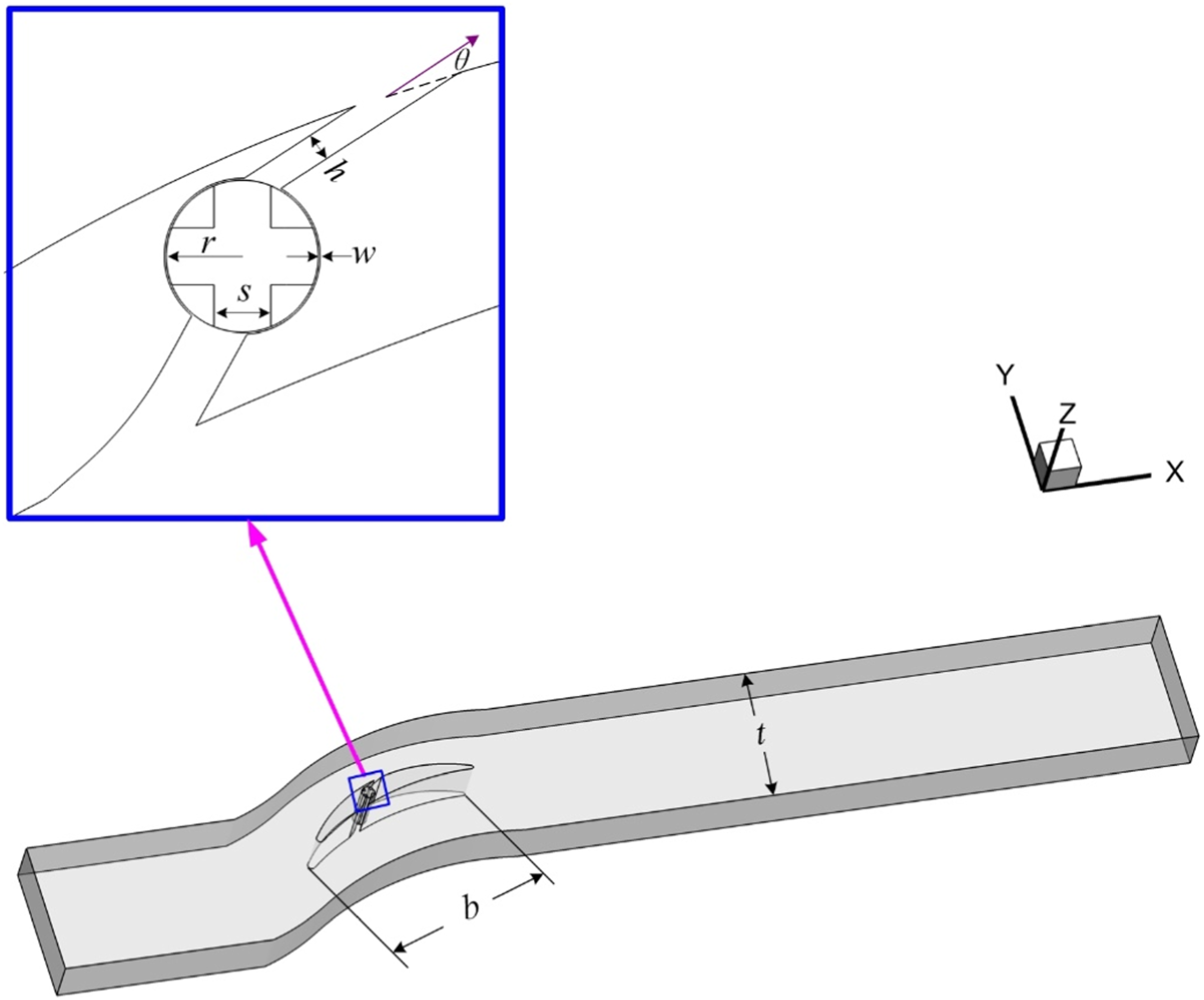
To avoid the disadvantages of active unsteady flow control discussed in the Introduction, a new concept of the self-driven pulsed jet installed on a compressor stator blade, which is a passive unsteady flow control method, is proposed in this study. This concept, without using any external flow or electrical source, can reduce the structural complexity of the flow control system and improve engineering practicability. The diagram of this concept is illustrated in Figure 1. Diagram of the self-driven pulsed jet on a compressor stator blade.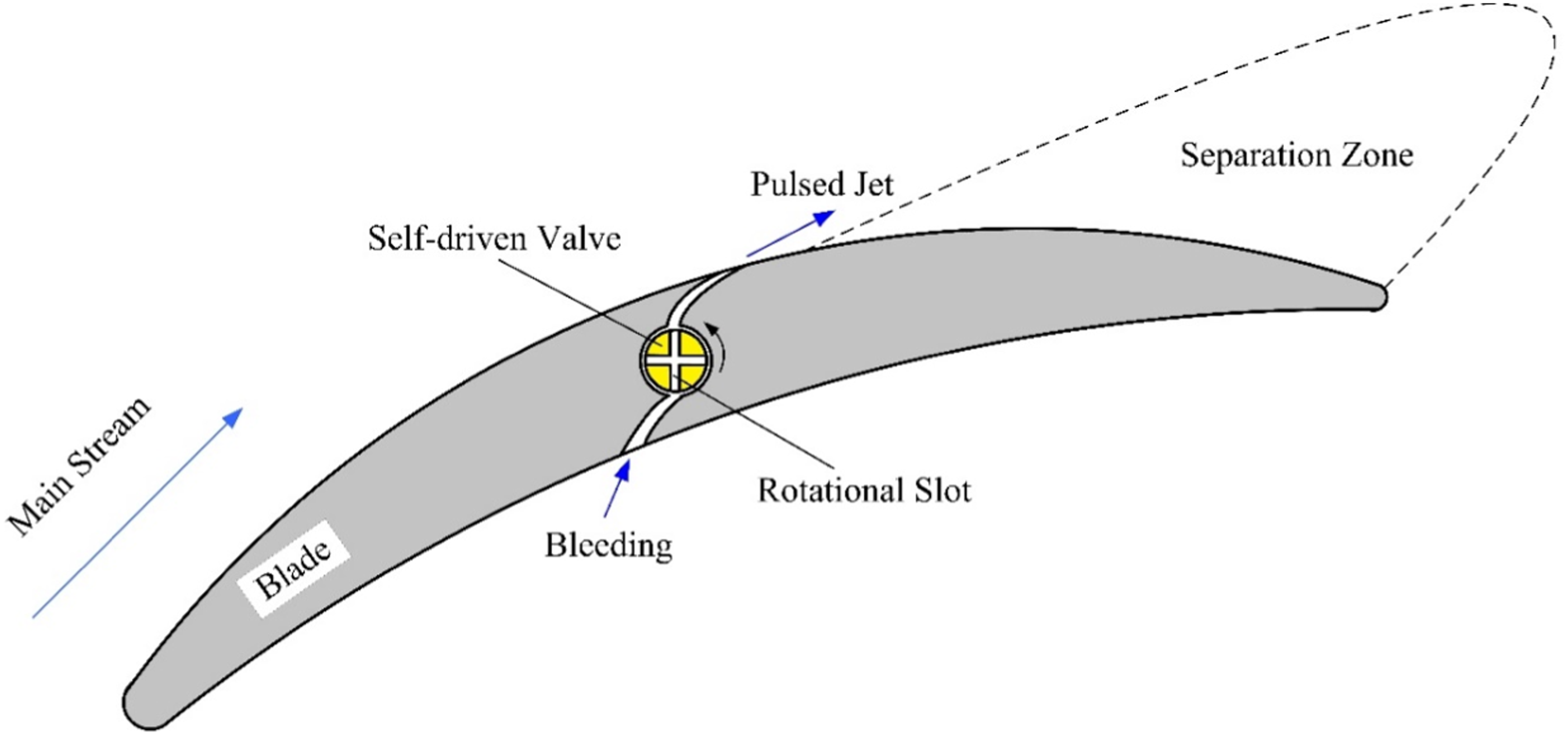
Figure 1 shows a typical highly loaded compressor stator blade with flow separation on the suction surface. Like the slotted blade, a jet slot that bridges the pressure and suction surfaces to form a flow path is built into the blade. Utilizing the pressure difference between the pressure and suction surfaces of the blade, the jet slot can inhale air at the pressure surface and generate a jet at the suction surface. Furthermore, a rotational cylindrical self-driven valve with slots is installed on the path of the jet slot. The self-driven valve has two functions: a valve and an air turbine. As an air turbine, via the aerodynamic design of the jet slot, the self-driven valve can extract energy from the pressure difference between the pressure and suction surfaces and overcome the air and bearing resistance to keep rotating. The self-driven valve rotates; thus, the rotational slots on it open and close the flow path formed by the jet slot at a certain frequency. As a result, a pulsed jet is formed at the outlet of the jet slot and its frequency depends on the rotational speed of the self-driven valve. In this passive unsteady flow control method, the pressure difference between the pressure and suction surfaces of the blade is very important and plays two roles. One is as an interior flow source to provide energy for the jet, and the other is as an energy source to power the rotational valve to generate the unsteadiness of the jet. By doing so, the flow or electrical source, as that in active unsteady flow control, is avoided. The concept of the self-driven pulsed jet on a compressor stator blade is among the few passive unsteady flow control methods and has the following advantages. a. Passivity and self-driven. The jet energy comes from the compressor flow field without an external flow source; the compressor flow field also drives the actuator and no electrical source is needed to generate the unsteadiness of the jet. b. Unsteadiness. The pulsed jet is an unsteady flow control which is more efficient than steady jet flow control. c. Simple structure. Without using any external flow or electrical source and resultant flow and electric circuits, the structure of the flow control system is relatively simpler, compared with active flow control.
Basic theory of the self-driven pulsed jet on a compressor stator blade
This section briefly discusses the basic theory of the proposed self-driven pulsed jet in Section 2. When the self-driven valve is on, as illustrated in Figure 2, it plays the same role as an air turbine, and the inlet and outlet of this turbine are denoted by cross Sections 1 and 2. For simplicity, incompressible and inviscid flow is considered. According to the incompressible Bernoulli equation in Sections 1 and 2, Schematic diagram of the self-driven pulsed jet on a compressor stator blade and corresponding velocity triangles.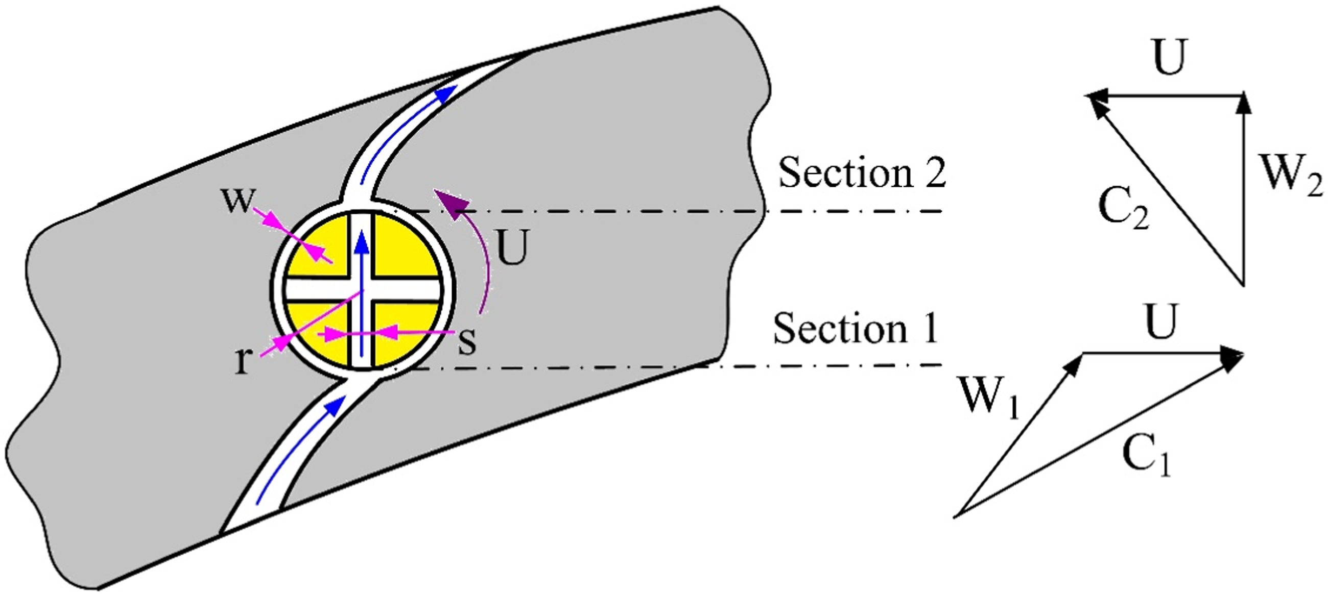

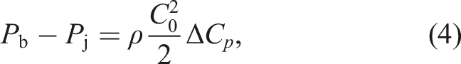
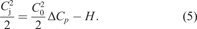
According to the Euler turbine equation and the velocity triangle illustrated in Figure 2,


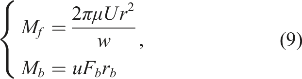

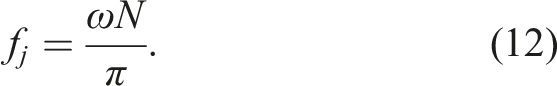
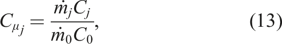
The momentum coefficient of the pulsed jet is defined as follows:
Numerical simulation of a self-driven pulsed jet on a compressor cascade
Numerical methods
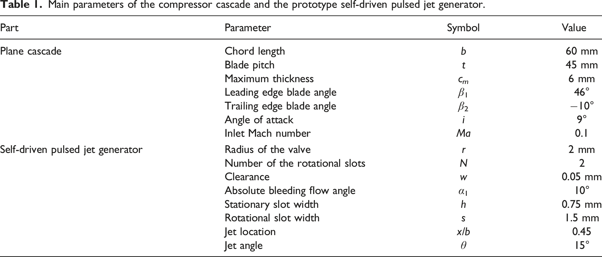
Main parameters of the compressor cascade and the prototype self-driven pulsed jet generator.
Model of the self-driven pulsed jet on a compressor stator blade.
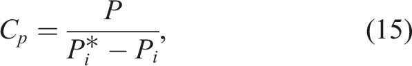
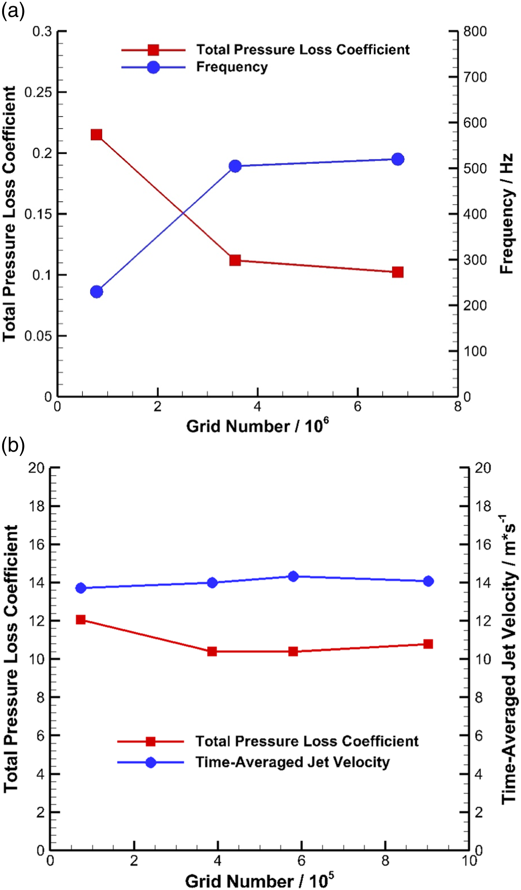
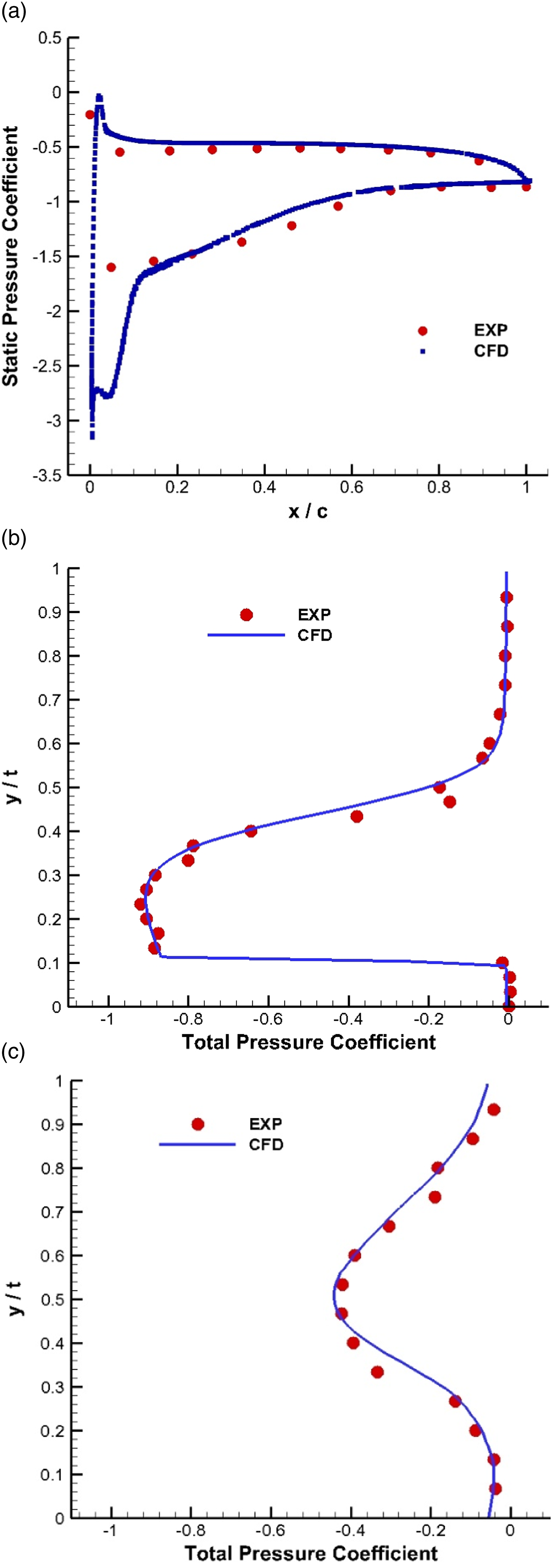
Three-dimensional (3D) large eddy simulation (LES) is performed using the flow solver Ansys Fluent to prove the concept preliminarily and obtain the characteristics of the self-driven pulsed jet on a compressor stator blade. In LES, a steady flow field computed by the shear stress transfer (SST) k-ω turbulence model is used as the initial field, whereas, for the unsteady simulation, the wall-adapting local eddy-viscosity (WALE) sub-grid model is used. The pressure boundary conditions at the inlet and outlet of the cascade are given to ensure the inlet Mach number approximately equals 0.1. In the pitchwise direction, the computational domain stretches one pitch (45 mm) of the cascade and transitional periodic boundary conditions are applied on the pitchwise boundaries. While in the staggering (spanwise) direction, only 10-mm height (1/6 the chord length) is covered by the mesh, and transitional periodic boundary conditions are also applied to reduce the computational cost. This study uses dual time stepping, and the physical time step is set as 1 × 10⁻⁵ s so that the convective Courant–Friedrichs–Lewy (CFL) number is less than 1. Concerning the grids, a structured grid is used, and near-wall layers are densified to ensure Grid dependence results. (a) The baseline cascade; (b) the self-driven device. Comparison between experimental (data from Ref.
23
) and numerical results (Ma = 0.1). (a) Blade loading distribution; (b) pitchwise total pressure coefficient (at the trailing edge); (c) pitchwise total pressure coefficient (One chord length downstream the trailing edge). Mesh of the cascade and self-driven pulsed jet generator.
Numerical results and discussion
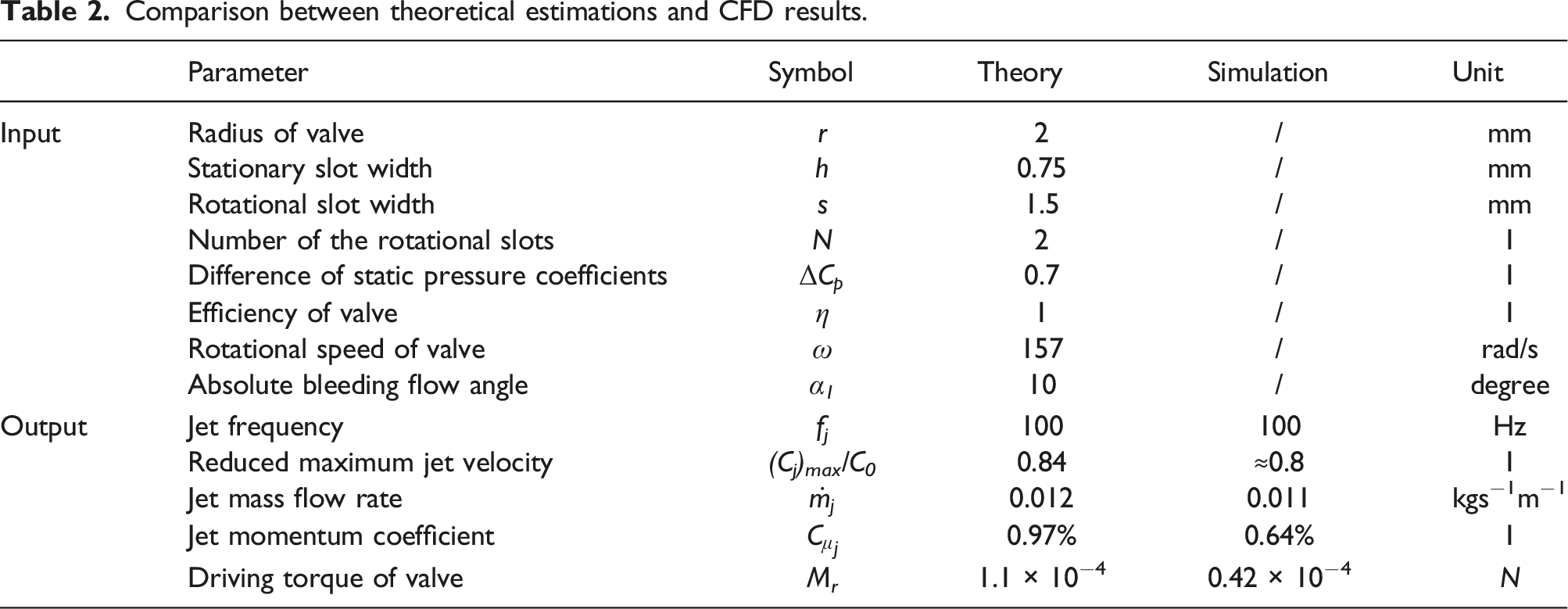
Comparison between the theoretical and simulated results
Comparison between theoretical estimations and CFD results.
Analysis of time-averaged characteristics
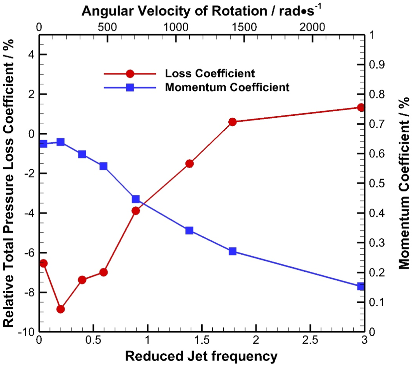
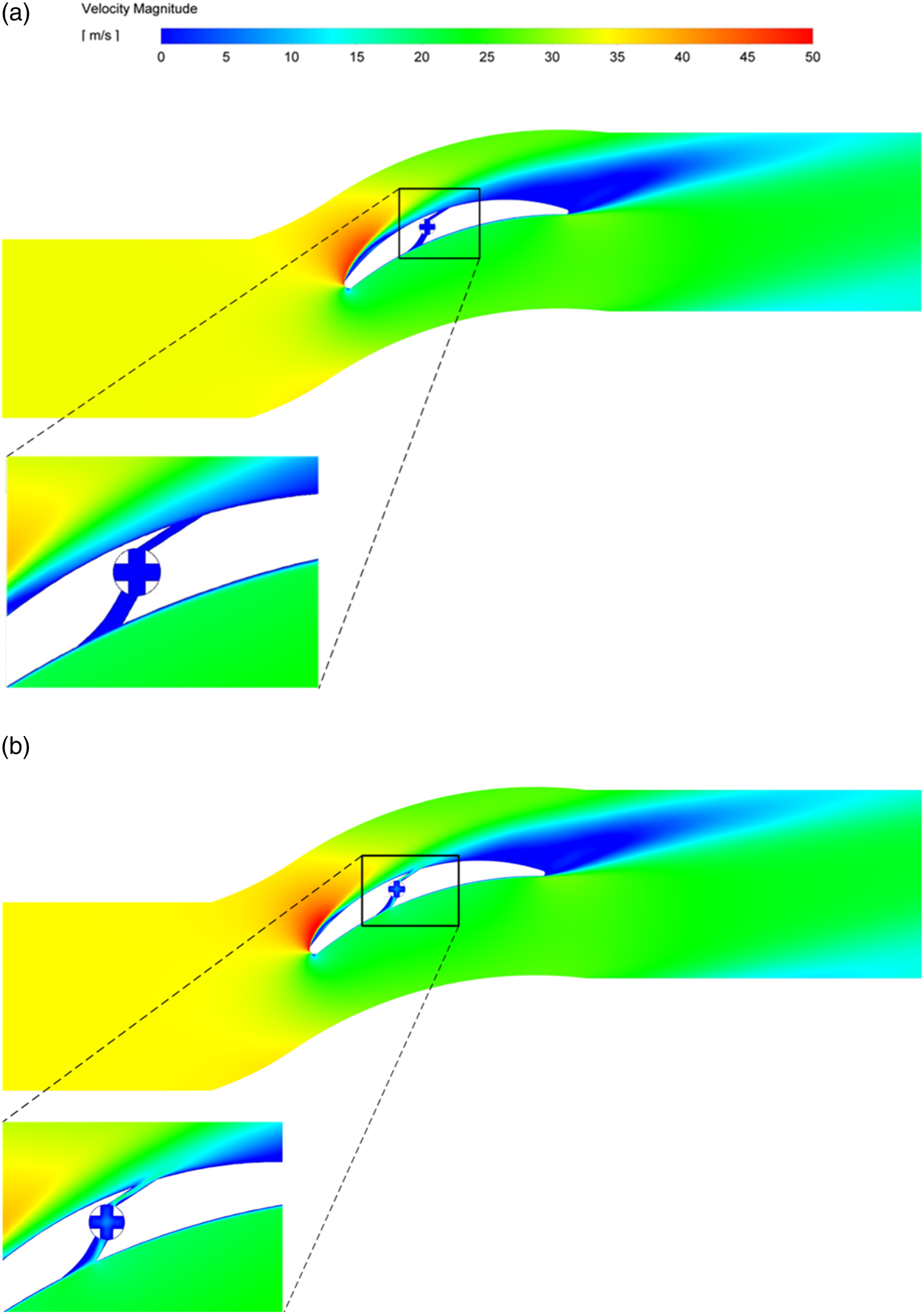
The time-averaged characteristics of the self-driven pulsed jet when the valve is under different rotational speeds are analyzed in this section. Equation (12) indicates that the pulsed jet frequency is proportional to the rotational speed of the valve. Figure 7 shows the variations of the total pressure loss and momentum coefficients with the rotational speed of the valve. In the figure, the reduced frequency is defined as follows: Total pressure loss and momentum coefficient variations with the angular velocity or reduced jet frequency of the self-driven valve. Time-averaged velocity contour: (a) self-driven pulsed jet in off status (baseline); (b) self-driven pulsed jet in on status (
This index has the physical meaning of the saved momentum (benefit) divided by the momentum injection of flow control (cost). Control efficiency variation with reduced jet frequency.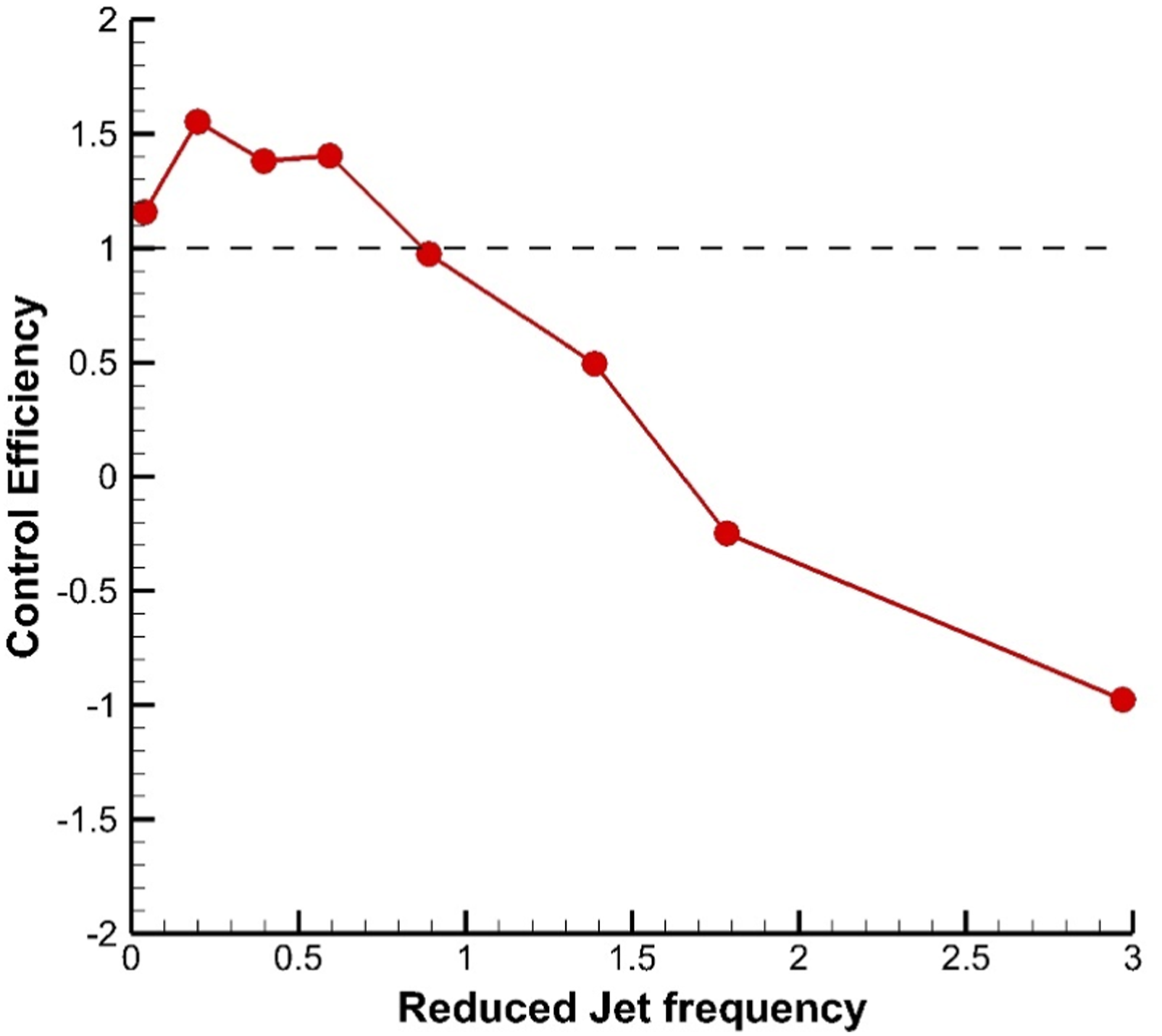
This study's optimum is different from the previous finding that the optimum control performance is at
Analysis of unsteady characteristics
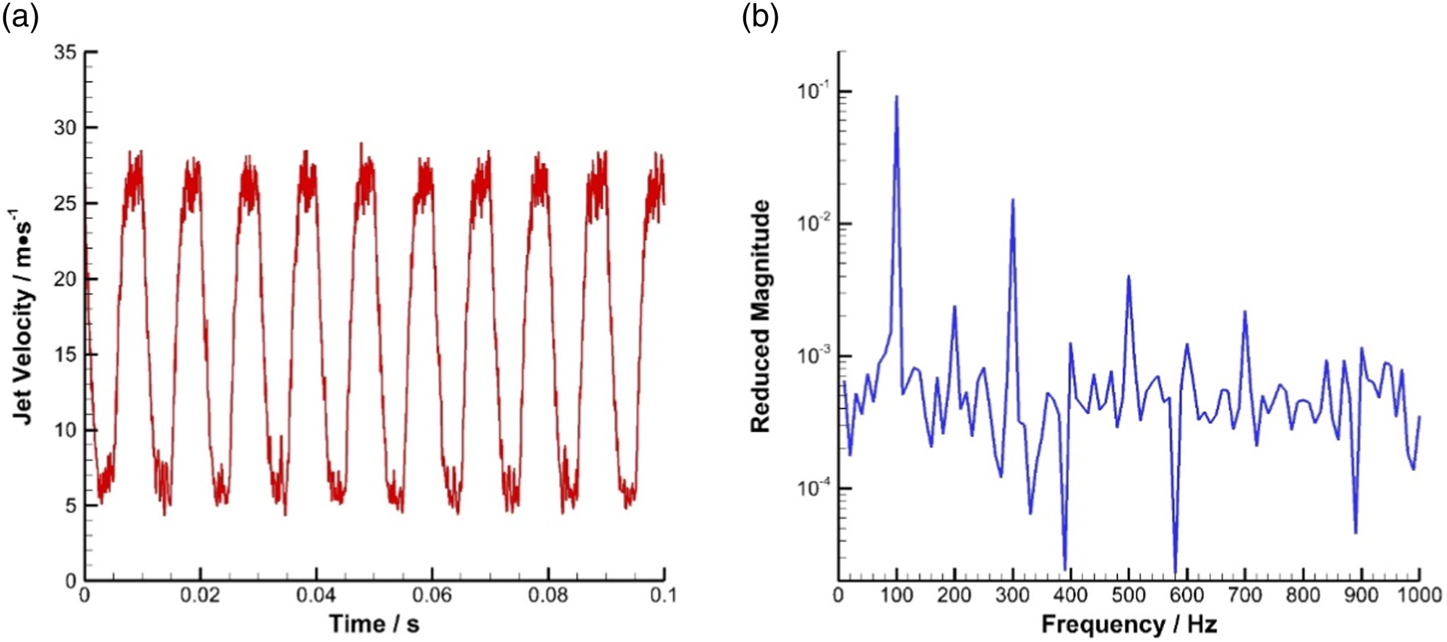
The previous section analyzes the characteristics of the self-driven pulsed jet in a time-averaged sense and focuses on its unsteady characteristics. Figure 10 shows the time domain and frequency spectrum of the pulsed jet velocity monitored at the outlet of the jet slot when the jet frequency equals 100 Hz. The time domain curve of the jet velocity is close to a periodic square wave signal, and the velocity ranges from approximately 5 m/s (Cj/C0 ≈ 0.15) to 28 m/s (Cj/C0 ≈ 0.8). The lowest value of the pulsed jet is not zero because of the clearance between the self-driven valve and the compressor stator blade; thus, the valve cannot be completely closed. The periodicity of the pulsed jet velocity can be reflected by the frequency spectrum obtained by fast Fourier transformation (FFT), as illustrated in Figure 10(b). The peak of the dominant frequency of 100 Hz, along with some of its harmonics, can be found in this spectrum. Furthermore, the odd harmonics outstand the nearby even ones in amplitude because an ideal square wave only consists of odd harmonics, which can be expressed mathematically as follows: Unsteady characteristics of the self-driven pulsed jet velocity (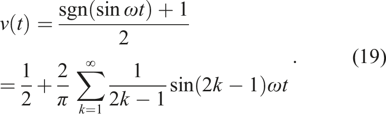
The driving torque on the self-driven valve is also unsteady. In Figure 11, the non-dimensional driving torque of the self-driven valve is defined as follows Driving torque and jet velocity over two periods (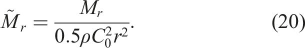

It is illustrated over two periods (the period is denoted by T). The driving torque has the same frequency as the jet velocity. However, its phase is ahead of the jet velocity for about a quarter of the period. In the present design, the driving torque can be either more than or less than zero, indicating that the driving torque's direction can be the same and the opposite of the rotational direction. To explain this phenomenon further, typical snapshots of velocity contour at t = 1T, 1.3 T, and 1.6 T in Figure 11 are shown in Figure 12. At t = 1T, the rotational valve is open, and the jet pushes the right wall of the valve, serving as a driving force, so the driving torque is positive. At t = 1.6 T, the jet pushes the right wall of the valve, serving as a resistance force. Thus, the driving torque is negative. However, at t = 1.3 T, the rotational valve is closed; thus, the driving torque is close to zero. Given that the rotational valve has inertia. The time-averaged driving torque is more important than its unsteady characteristics when the torque on the valve is in equilibrium. Thus, the time-averaged driving torque, which is closely relevant to the self-driven and self-starting characteristics of valve, will be discussed in the next section. Typical snapshots of the transient velocity contour within one period (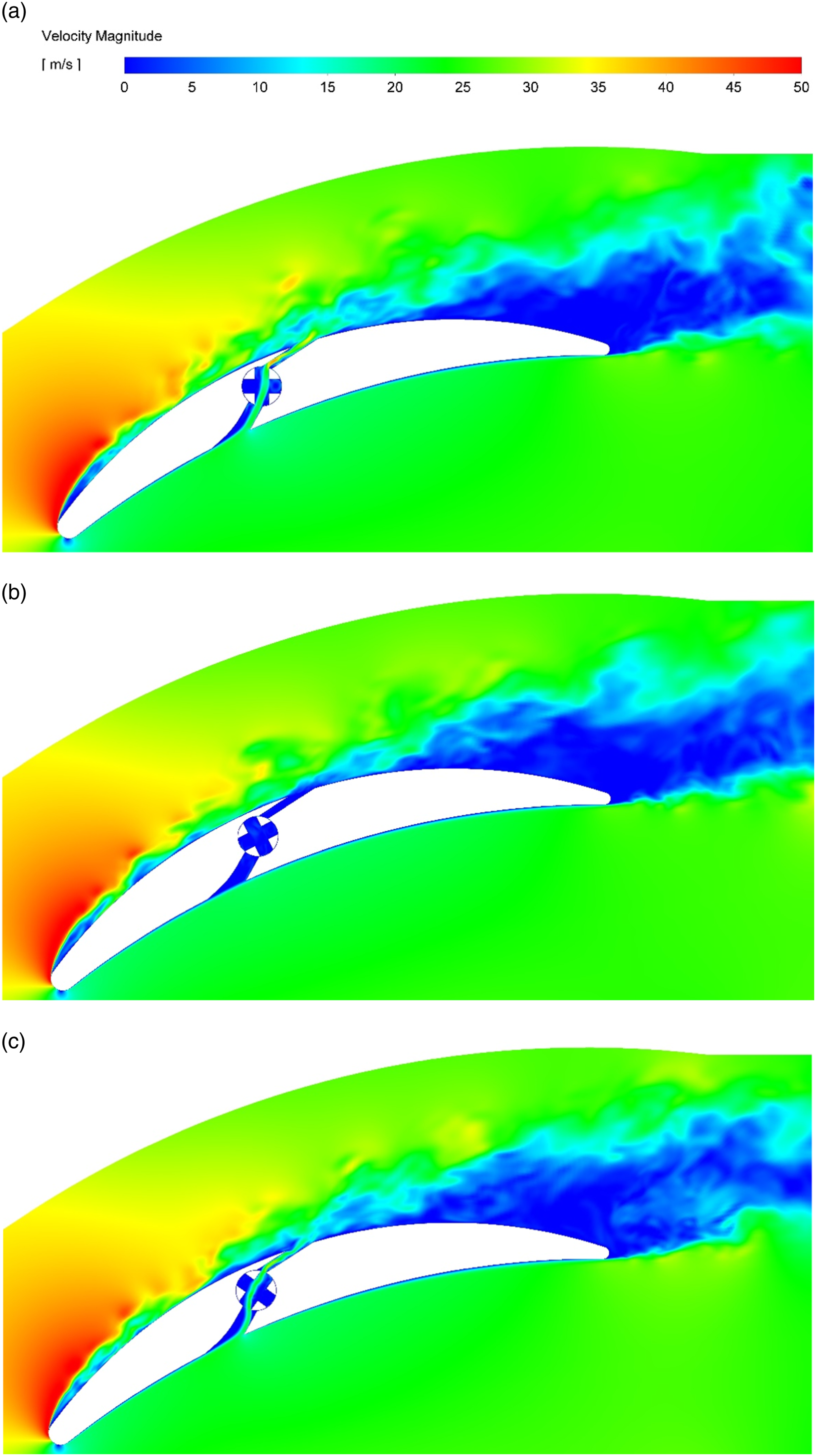
Analysis of self-driven and self-starting characteristics
An important advantage of the self-driven pulsed jet is being passive, which means the actuator should self-start and be self-driven. Indicated by unsteady characteristics in Figure 12, if the initial position of the valve (when its rotational speed is zero) is at an off status, the driving torque of the valve is close to zero, then the valve cannot self-start and rotate to the designed rotational speed. This problem can be solved by substituting the aligned rotational slots in this study with the staggered rotational slots, as illustrated in Figure 13, so that a part of the valve always stays at an open status and produces a non-zero driving torque to help the valve to start. Different types of self-driven valves: (a) with aligned rotational slots; (b) with staggered rotational slots.
Another issue is whether the valve could be self-driven or self-sustained at a certain rotational speed. This issue is related to the time-averaged driving torque on the valve. Figure 14 shows the time-averaged driving torque variation with the angular velocity of rotation in the simulation. The driving torque keeps positive. It increases when the rotational speed is between 30 and 700 rad/s and decreases when rotational speed is between 700 and 2500 rad/s. It is negative when the rotational speed is above 2200 rad/s. According to Figure 2 and equation (10), the increasing driving torque between 30 and 700 rad/s is caused by the reduction in the angle of attack of the relative flow velocity W1 to the rotational slot and resultant higher efficiency η of the valve as an air turbine. The driving torque decreases when the rotational speed is approximately 700 rad/s because isentropic-specific work H drops with the increasing linear velocity at the surface of the self-driven valve U, as indicated by equation (6). Time-averaged driving torque variation with the angular velocity of rotation.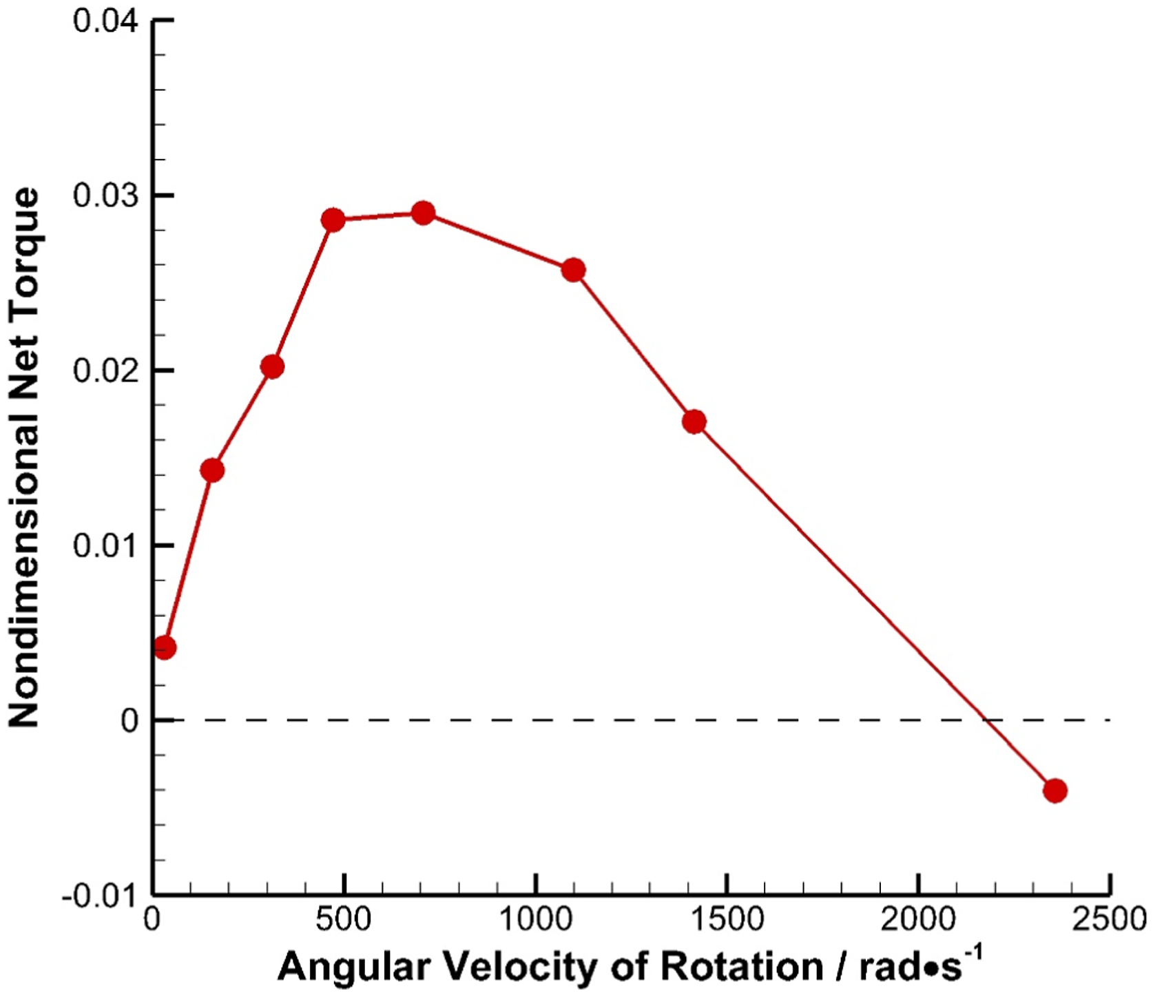
With the time-averaged driving torque characteristics illustrated in Figure 14, the self-driven and self-starting characteristics of the self-driven pulsed jet can be analyzed. Three circumstances were considered that are distinguished by whether the rotational valve can self-start or be self-driven, as illustrated in Figure 15. As shown in Figure 15(a), if the bearing resistance torque is lower than the driving torque Mr at Self-starting characteristics of the self-driven valve: (a) can self-start and be self-driven; (b) cannot self-start but can be self-driven; (c) cannot self-start nor be self-driven.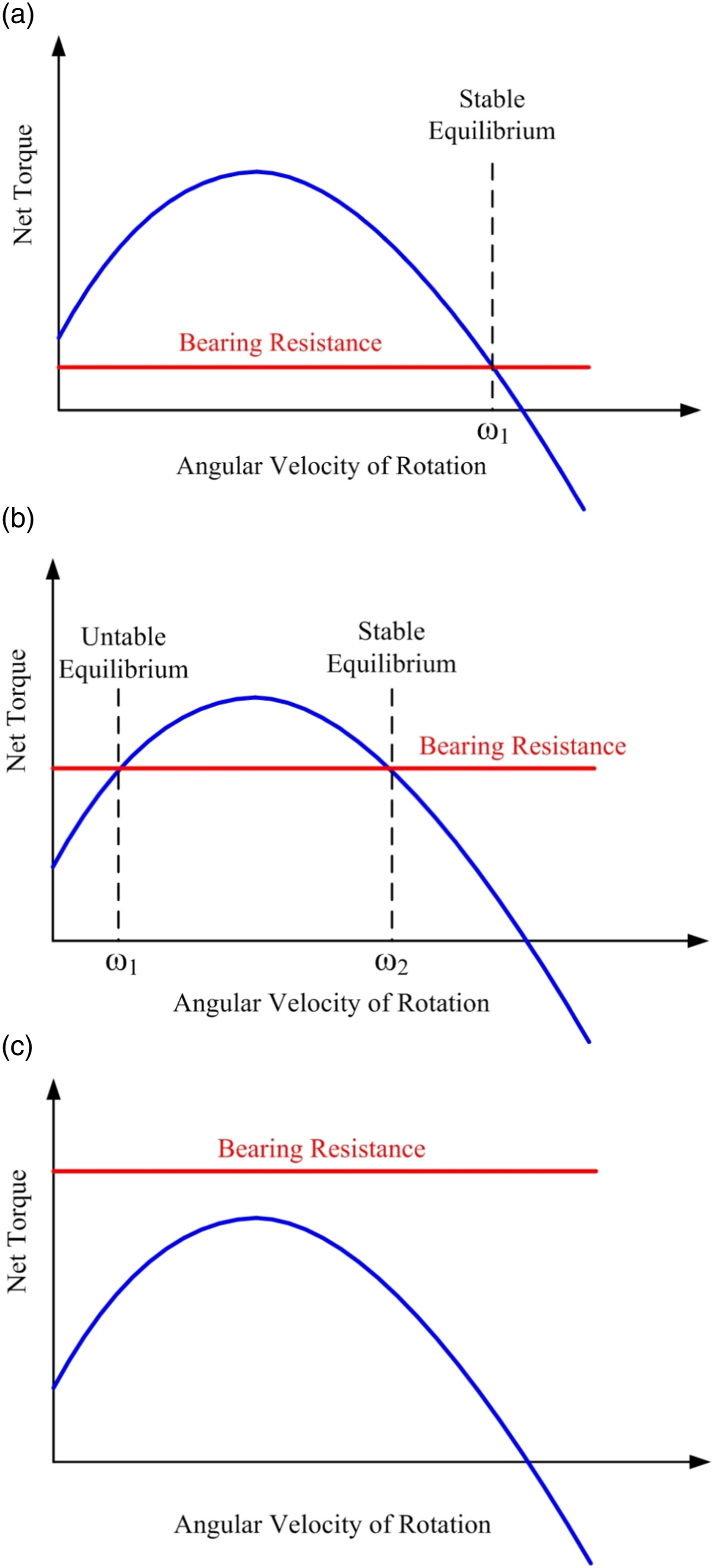
In this section, the proof-of-concept study of the self-driven pulsed jet is preliminarily carried out by numerical simulation. The numerical results confirm that the passive unsteady flow control method can produce an unsteady jet and a positive control performance without employing any external flow or electrical source. Moreover, the self-driven and self-starting characteristics of the valve are discussed. This study is only a preliminary attempt to prove the concept; thus, many aspects can still be improved. Apart from the general unsteady flow control parameters, including jet location, momentum coefficient, and angle, which can be further optimized, the geometry of the self-driven pulsed jet generator, along with the stationary and rotational slots, needs to be optimized to reduce flow losses. The reason is that no aerodynamic shape is used for them in this proof-of-concept study. Furthermore, the control performance and the self-driven and self-starting characteristics are based on the present design. Thus, the results may be different if a future state-of-the-art design (e.g., the design presented in Figure 13(b)) is employed.
It is worth noting that only one major working condition, for example, the blade working under the design point, is considered in this paper. It is thought by us that the performance will definitely change under off-design points. The self-driven valve is essentially an air turbine, and when the angle of attack or Mach number of the compressor blade increases, the pressure difference between the two sides of the self-driven valve will become larger, thus generating more driving power and making the rotational speed faster. As a result, the pulsed jet frequency and jet velocity also increase. Also, when the angle of attack or Mach number of the compressor blade changes, the natural frequency of the separation vortex and the required momentum for the pulsed jet also change. Therefore, as the angle of attack or Mach number changes, flow control performance of the blade will change, but the specific flow control characteristic needs to be determined by further numerical simulations.
Conclusions
This study proposes a new passive unsteady flow control concept of the self-driven pulsed jet method to avoid any external flow or electrical source common in active flow control methods. The self-driven valve serves as both a valve and an air turbine. The pressure difference between the pressure and suction surfaces of the blade has the function of providing energy for the jet and the valve to rotate to generate a jet with unsteadiness. The control effectiveness of the self-driven pulsed jet is preliminarily proven via numerical simulation. Also, the unsteady and self-driven characteristics are discussed. The main conclusions are listed as follows: 1. The numerical simulations preliminarily verify the effectiveness of the self-driven pulsed jet on a typical low-speed compressor stator blade. When the pulsed jet frequency is 100 Hz (or the reduced frequency 2. Analysis of the unsteady characteristics of the self-driven pulsed jet shows that the jet velocity is close to a periodic square wave signal and the typical velocity ranges from approximately 5 m/s (Cj/C0 ≈ 0.15) to 28 m/s (Cj/C0 ≈ 0.8). The driving torque on the valve has the same frequency as the jet velocity. In the present design of the self-driven valve, the torque can be larger than, equal to, and less than zero when the valve rotates in different directions. 3. The time-averaged driving torque on the valve is dependent on the rotational speed. In this study, the driving torque keeps positive, increases when the rotational speed is between 30 and 700 rad/s, and decreases when the rotational speed is between 700 and 2500 rad/s. However, the driving torque is negative when the rotational speed is above 2200 rad/s. This feature makes the self-driven valve behave differently under different bearing resistance torque. If the bearing resistance torque is lower than the driving torque Mr (
Footnotes
Acknowledgments
This research was funded by the National Natural Science Foundation of China (grant number 52106046 and 52106246) and the Natural Science Foundation of Jiangsu Province (grant number BK20200680). The authors wish to express their gratitude to Department of Engineering Mechanics (affiliated with School of Physical and Mathematical Sciences, Nanjing Tech University) for technical support.
Declaration of conflicting interests
The author(s) declared no potential conflicts of interest with respect to the research, authorship, and/or publication of this article.
Funding
The author(s) disclosed receipt of the following financial support for the research, authorship, and/or publication of this article: This work was supported by the National Natural Science Foundation of China (grant number 52106046 and 52106246) and the Natural Science Foundation of Jiangsu Province (grant number BK20200680).