
Abstract
The aircraft Environmental Control System (ECS) enables the aircraft to maintain a comfortable and safe environment for its passengers throughout its operating envelope. The Pressurised Air Conditioner (PACK) is the heart of the ECS, and is composed of multiple sub-systems: heat exchangers, valves, compressor, turbine, and a water separator. The PACK’s principle function is to enable conditioning of the hot, high pressure bleed air from the engine or APU, for temperature, pressure and humidity against the cabin requirements. The operation of the PACK is governed by a control system which has the ability to mask degradation in its component during operation until severe degradation or failure results. The required maintenance is then both costly and disruptive. The PACK has been reported as major driver of unscheduled maintenance by the operators. The aviation industry is currently proactively exploring innovative health management solutions that aid the maintenance of aircraft key systems based on predictive based maintenance approaches using online condition monitoring techniques. This paper presents a comprehensive review of the simulation and diagnostic methodologies applicable to fault diagnostics of the ECS PACK. The existing literature suggests that model-based and data-driven methods are effective for conducting fault detection and isolation of the PACK system. The conceived findings indicate that the model-based diagnostic approach have been extensively employed to conduct PACK diagnostics at component level only. Their successful implementation requires robust experimental verification and validation against the actual data under healthy and faulty conditions. Although a substantial amount of work has been reported on developing first principles based simulation models and diagnostic strategies for the ECS, the acquired findings suggest that there is a compelling need for a verified and validated ECS simulation model to enable accurate PACK system-level diagnostics based on single and multiple component level degradation scenarios. It has also been identified that the existing literature lacks the evaluation of humidity regulation and the effect of the control system on the PACK performance characteristics. Finally, a taxonomy of diagnostic techniques and simulation models is compiled based on the available literature.
Introduction
The Environmental Control System (ECS) of an aircraft provides conditioned air to pressurise the cabin and regulate the temperature and humidity throughout cabin. It also supplies the cooling air into the avionics bay to prevent the electronic equipment from overheating. It contains two Passenger Air Conditioners (PACK), which are the primary system for conditioning the airflow within the ECS. 1 Although the system is quite robust, there have been a few incidents reported due to system failure. A simple ECS component fault occurrence can escalate and result in system failure. For example, a Ram air actuator failure can result in reduction of cold mass flow over the heat exchanger causing an instant PACK shutdown due to overheating. 2 Overheating can also occur due to a change of the bleed air source at the PACK input. 3 These incidents of PACK failure affect the pressurisation of the cabin. The PACK functionality is also crucial for maintaining humidity level in the cabin as overheating of excess moisture can cause misting in the cockpit, and the cabin, which can hinder the safety of passengers and crew. 4 The operations of the PACK are governed by the control system which has the ability to mask degradation in its component during operation until severe degradation or failure results. The required maintenance is then both costly and disruptive. The PACK has been reported as major driver of unscheduled maintenance by the operators. The aviation industry is currently proactively exploring innovative health management solutions that aid the maintenance of aircraft key systems based on predictive based maintenance approaches using online condition monitoring techniques.
The safety of the crew and operational cost was a major concern when NASA began human space flight. 5 After the Apollo success, the concept of Integrated Vehicle Health Management (IVHM) began to surface in the 70s to address the safety and cost factors. In 1992, NASA defined the IVHM goals and objectives in a report. 6 These objectives can be summarised as the capability to facilitate optimised maintenance actions, operational cost reduction, improved readiness of the fleet and enhanced safety. 7
Zhang et al. 8 suggests that civil aviation maintenance costs are estimated to make up 10% of airline operating cost, with spending reported to be around US$83 billion in 2019. Considering the industry efforts to build and recover from the Corona Virus 2019 (COVID19), these costs are anticipated to reach US$115 billion by 2030. This motivates airliners to take the IVHM concept developed by NASA further by integrating health monitoring technologies into their asset. 9 It helps in monitoring the critical components of a system of their asset and cuts down on unscheduled maintenance and downtime. 10 Thus, the use of IVHM toolsets is enabling a shift from preventive maintenance over to the predictive maintenance.
The data collected from the aircraft are instrumental in conducting diagnostics and prognostics using the model-based or data-driven technique. A vehicle level reasoning system can be used to identify faults considering the interaction between different systems. 11 In order to understand interdependencies between components, and to enable accurate diagnostics, there is a need to develop system-level simulation models. The fault detection and prediction analysis can dictate the supply-chain and logistics to best prepare for scheduled maintenance, creating the new manufacturing paradigm supporting predictive maintenance 12 [p. 4].
Environmental control system
Air conditioning systems are designed to provide conditioned air ensuring human comfort. They are applicable in aircraft, automobile, offices, industries and various other places. During the mid-1940s, the pioneering Boeing 307 Stratoliner was the first aircraft equipped with air conditioning system, ECS, for cabin pressurisation. This enabled high altitude flights within thin air and sub-zero temperature regions above the weather and turbulence.13,14
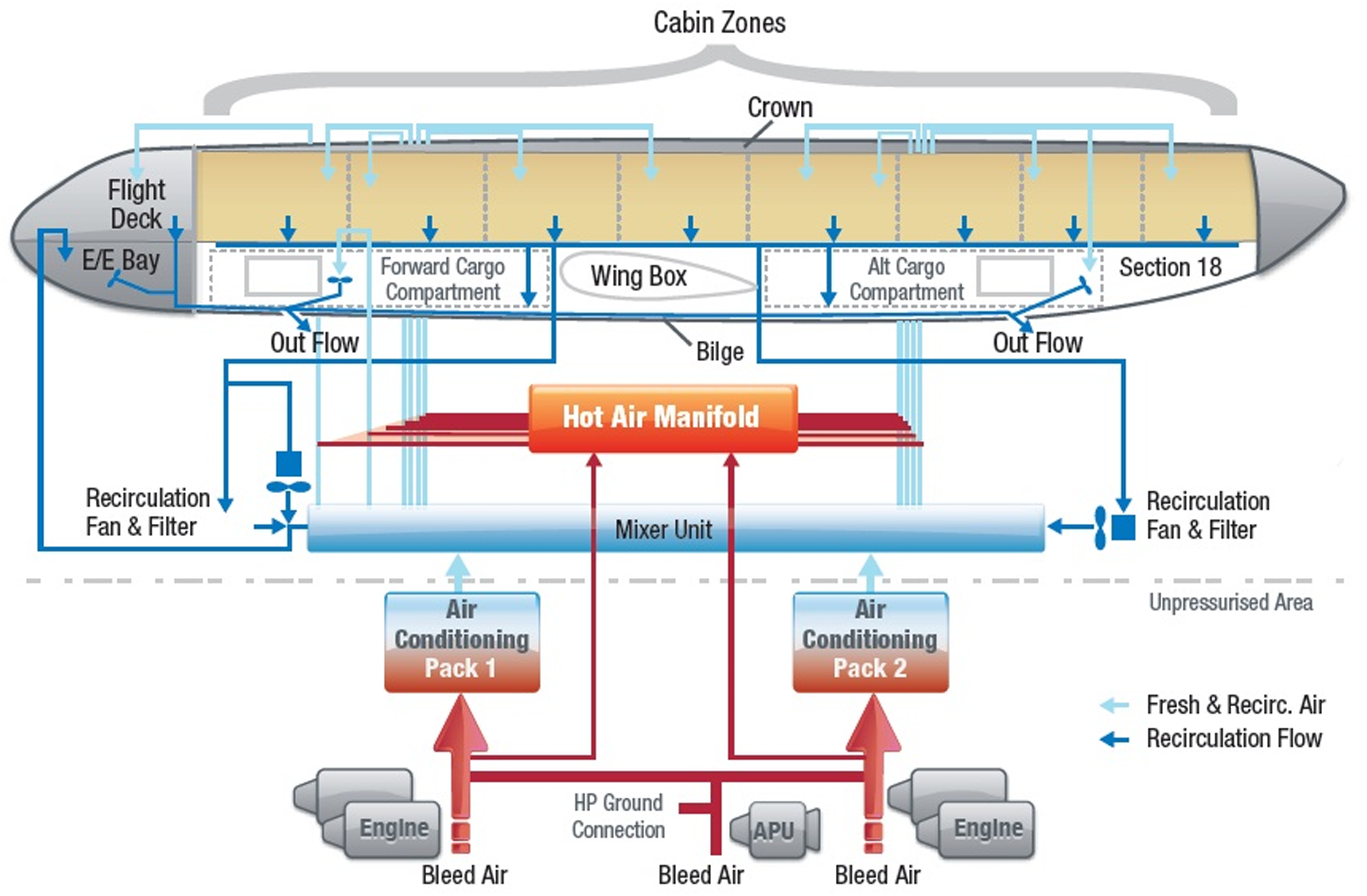
ECS is a generic term for the subsystems and equipment associated with ventilation, heating, cooling, contamination control, and pressurization in the occupied compartments, cargo bays and electronic racks. As illustrated in Figure 1, the overall environmental control system of a typical civil aircraft is composed of several subsystems, which are the Bleed Air System (BAS), the Anti-Icing System (AIS), the Pressurized Air Conditioner (PACK) and the Cabin Pressure Control System (CPCS). The bleed system provides the pressurised air to the PACK for conditioning. Part of the bleed mass flow before entering the PACK is taken out to drive the Ram turbofan to drive cold ambient air over the heat exchangers in the PACK to enable pre-cooling of the bleed air. After conditioning of the bleed air in the PACK, the air is mixed with trim and recirculating air from the cabin in the mixing manifold before it is distributed to different zones of the aircraft. ECS schematic.
15
The PACK is the primary system for conditioning the airflow within the ECS. Figure 2 illustrates the schematic of a single PACK with HPWS in a B737-400 aircraft. It consists of Valves, Heat Exchangers, an Air-Cycle Machine (ACM) and a High-Pressure Water Separator (HPWS). There are other ECS systems, such as electrically driven ECS (used in modern aircraft)
16
[p. 3], pneumatic ECS with low-pressure water separator (LPWS) (generally used in older generation aircraft),
17
vapour cycle ECS (used for light turboprop aircraft application)
18
and membrane-based dehumidifier (used in spacecraft).
19
Schematic of the 737–400 ECS PACK with HPWS.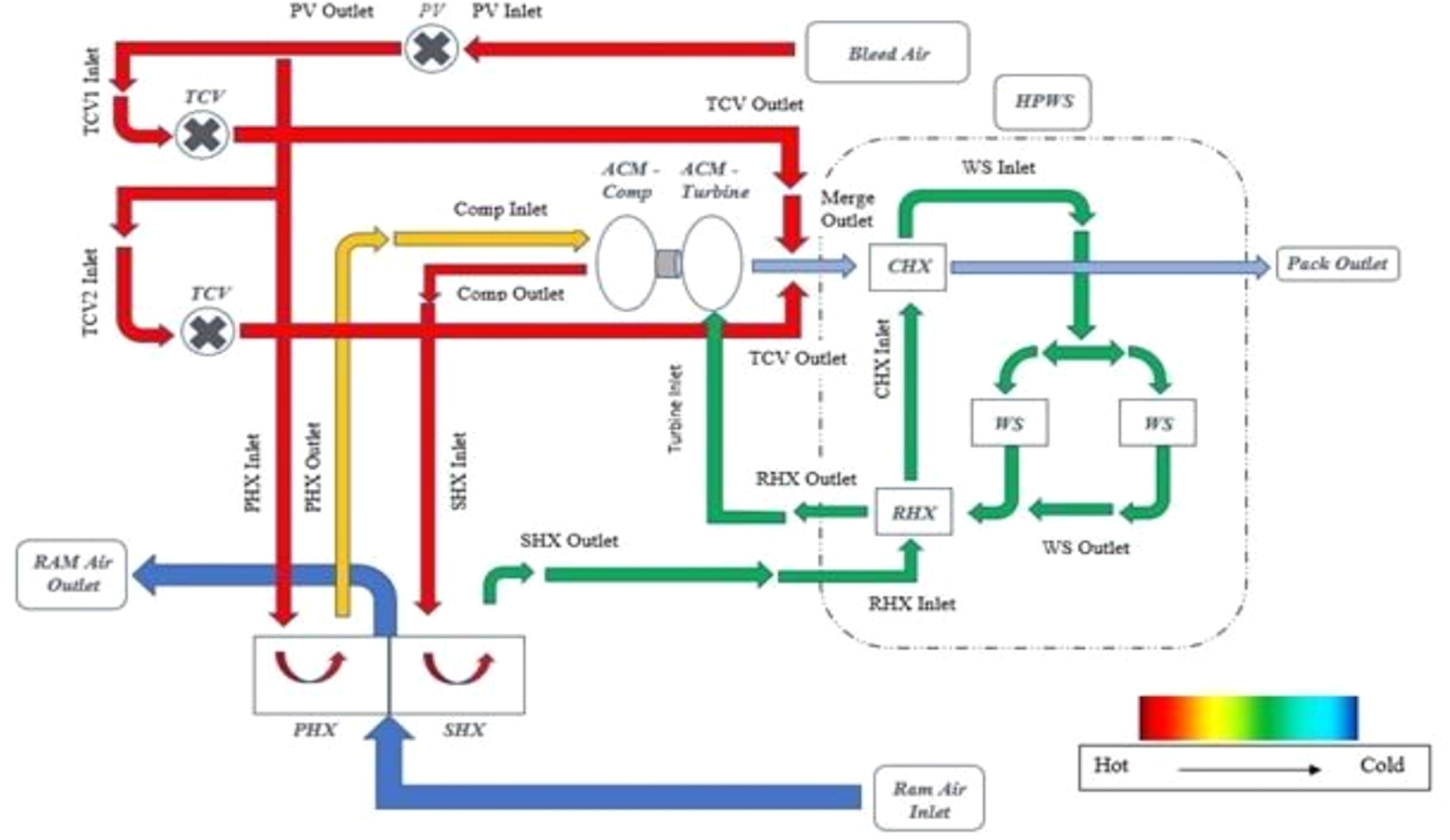
The PACK consists of a PACK valve (PV) and Temperature Control Valves (TCV) which regulate the hot mass flow through the system and the core. The Primary Heat Exchanger (PHX) and Secondary Heat Exchanger (SHX) use the cold Ram air as a heat sink. In between the heat exchangers sits the refrigeration unit of the PACK. The ACM drives the air through the core and contributes to cabin pressurisation. Towards the end of the PACK sits the HPWS consisting of Reheater (RHX), Condenser (CHX) and Water Separator (WS) which regulates air temperature to enable condensation and extraction of water from the air to regulate humidity. The PACK has a control system that governs the opening of the valve by using temperature sensors at the WS outlet (to regulate the TCV opening) and Compressor outlet (to regulate the Ram air mass flow modulating door) to meet cabin demand temperature. In addition to that, there are three temperature switches: at the compressor outlet, WS outlet and PACK outlet, which shut down the PV to prevent any damage to the system in the case of overheating.
Integrated vehicle health management
After the introduction of IVHM by NASA, the aviation industry started utilising it in accordance with the new Product Service System (PSS) business model. It helps in monitoring the critical components of a system of an asset and cuts down on unscheduled maintenance and downtime, defining the company’s profit margin. 10 Unscheduled maintenance plays a key role in increasing maintenance costs. Deploying IVHM tools on expensive assets such as the aircraft, raises the profit margin through the reduction in downtime during maintenance and as a result enhancing fleet availability.
Figure 3 distinguishes between preventive and predictive maintenance. The manufacturing sector of the aviation industry typically follows the preventive maintenance approach where the aircraft is grounded frequently for routine maintenance regardless of fault occurrences. This increases downtime as all critical components go through thorough inspection. The idea of IVHM is to monitor the health condition of the critical systems using sensor technology to detect and predict fault occurrences. At the fault prognostics stage shown in Figure 3, the remaining useful life of components is estimated, based on that maintenance actions are planned. The early detection of failure and prognostics helps cut down on unscheduled maintenance and also ensures the safety of passengers and crew. Maintenance flow chart: Preventive (left) and Predictive (right).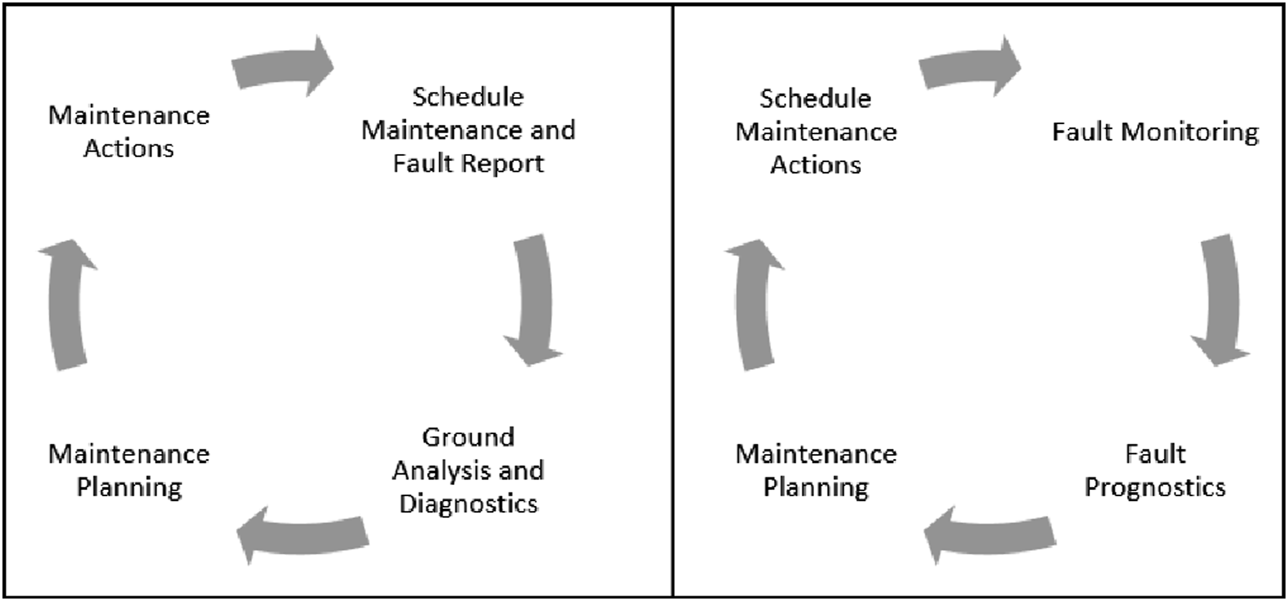
The sensor data collected from the aircraft is instrumental in conducting diagnostics and prognostics using a model-based or data-driven technique. In order to understand interdependencies between components to enable accurate diagnostics it requires development of system-level simulation model. Then a vehicle level reasoning system is used to identify faults considering the interaction between different systems. 11 This use of vehicle level reasoning proposed by Cordelia et al., 11 is a novel way of using reasoning to enable condition-based maintenance. The overall analysis of aircraft health condition and interdependencies between major systems can then be used to well prepare the maintenance actions. 12 [p.4]
Scope of present work
This paper provides a literature survey on the ECS towards its diagnosis which includes the following: (I) Identification of diagnostic methodologies applicable for the ECS (II) A review on system-level simulation models for the ECS (III) Experimental investigation on PACK performance
Diagnostic methodologies
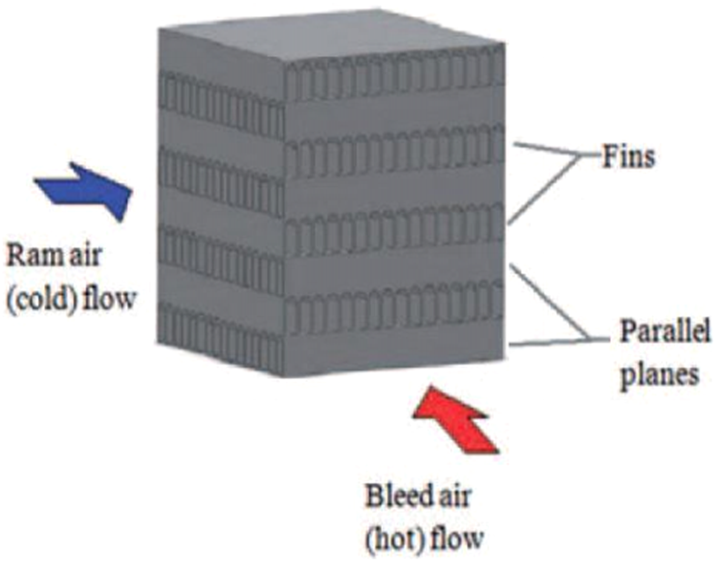
Heat exchangers within the PACK have been extensively investigated by researchers.20–23 The aircraft ECS heat exchangers are made of fin and plate assemblies as shown in Figure 4, which uses cold Ram air as a heat sink to cool the hot bleed air. The ram air often contains debris which accumulates at the cold-side of the heat exchanger resulting in a drop in heat exchanger effectiveness.
24
Due to drop in effectiveness, the heat transfer across the hot and cold side will be impacted and the system will overheat imposing a risk of immediate PACK shutdown. Therefore, the heat exchangers were considered to be critical components of the aircraft ECS system which requires appropriate diagnostic rules.
25
The diagnostic methodology that has been implemented can be classified as: (i) Model-based method,
26
(ii) Data-Driven method
9
and (iii) Hybrid method.
27
The hybrid method is a combination of both model-based and data-driven methods. Typical fin-and-plate type cross-flow heat exchanger.
24
Model-based method
The model-based method relies on a system model with the mathematical equations defining the input/output conditions.
28
This technique involves installing sensors at the optimised locations to acquire health defining parameters and comparing them against the model output. This sensor set is unique for each system and can be established by studying the thermodynamic PACK performance characteristics. This study of PACK performance characteristic under heat exchanger fouling is demonstrated by Jennions and Ali.
29
The heat exchanger fouling has been simulated in the model by manipulating the heat exchanger effectiveness. Their results suggest that the PACK performance under PHX and SHX degradation are very different to each other. The deviation between the model data (healthy baseline under given operating conditions) and test data can then be used as an indication of fault occurrences.[p.19]
30
Figure 5 demonstrates a typical model-based approach that relies on residual evaluation. The difference, or residual, is usually generated by one of three different methods: (i) Parameter Estimation, (ii) State-observer and (iii) Parity Space.
31
Concept of model-based diagnostic approach.
30
[p. 19]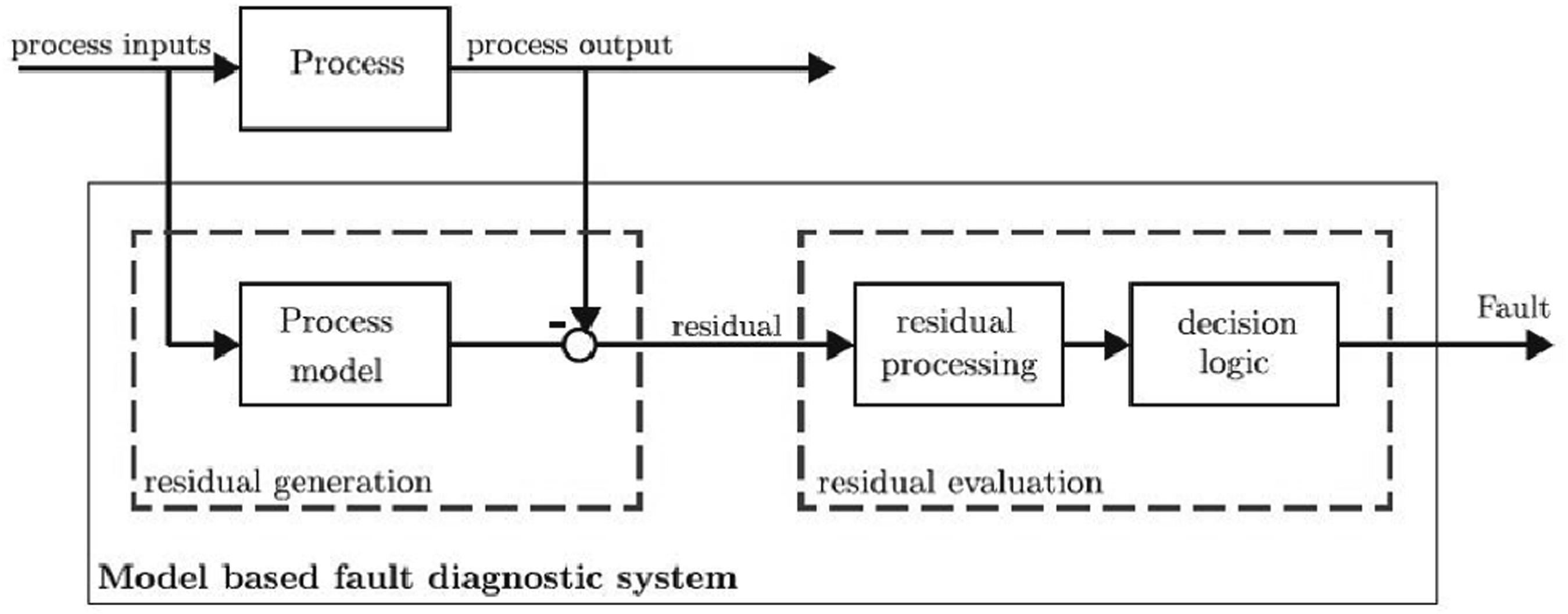
Parameter estimation and state-observer
Fouling in heat exchanger is due to particulate accumulation. This can occur in both the hot and cold side. Research indicates the parameters that need to be monitored for diagnosing heat exchanger fouling are the heat transfer coefficient, the pressure drop, the mass flow rates, the temperature variation and the weight of the plates.
32
Deviation in the estimated parameters over time is used as an indication of fault occurrences. To estimate the values of model parameters using parameter estimation method, a dynamic model of the system is required. An example of such dynamic model in the form of physical state space model representation of a heat exchanger proposed in Reference 32, where the hot inlet temperature (
The traditional EKF used to estimate the state parameters for detecting degradation or fouling can potentially lose its monitoring capability in case of abrupt changes in the process states. This problem was resolved using two Kalman filters, simultaneously forming a double model filter 23 which is used to trace fault-free and faulty state of a non-linear system. For both the methods, the selection of the initialisation value for the parameter can be difficult, for which an adaptive filter such as strong tracking filter (STF) is developed by Ma et al., 34 to improve the existing EKF that can be used to estimate the fault parameters. The STF is an extension of the EKF which has the capability to perform online state estimation regardless of the system reaching steady-state. 36 The authors also used a modified Bayes classification algorithm to detect and isolate fault. 34
Similarly, the state-observer method uses model input data to estimate state variables, based on suitable estimation method. Once the system output is reconstructed using the estimated state variables, error between the simulation and actual output is to be calculated which will be zero if the system is fault free, and vice versa. 30 For these two methods to be effective, it is essential to understand the input-output behaviour of the system. 37 For this, experimental component performance analysis is required.
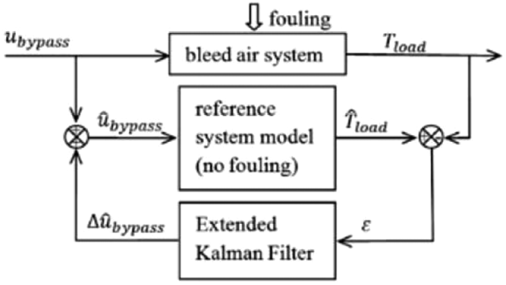
The heat exchanger fouling can also be detected by analysing the PACK control system. The PV and TCV regulate mass flow through the system to match cabin demand temperature. The variation in hot and cold mass flow affects the heat transfer coefficient. The valves are regulated by a control signal which drives the motor to rotate a butterfly valve. Given the ram mass flow is constant, estimating the deviation of valve command from fault free condition can also help identify heat exchanger fault occurrence. Shang and Liu
24
proposed that the fault detection of the heat exchanger can be monitored by estimating the deviation of valve control command using Kalman filter. The proposed methodology as shown in Figure 6 is based on the error (ε) between the output temperature ( Heat exchanger fouling detection method based on TCV control command.
24
The valves regulating the mass flows in the PACK are regulated using series of temperature sensors installed at various locations across the ECS. These sensors can be faulty which can affect mass flow through the core of the PACK. Wang and Wang 38 developed a fault diagnosis strategy by employing a genetic algorithm technique for parameter estimation which can be used to detect sensor faults.
Another approach to heat exchanger fouling detection was proposed and experimentally validated by Palmer et al., 22 where a manually initiated built-in-test (iBIT) method was used. Within parameter estimation method Rajarman.S et al., 39 used Kharitonov’s theory instead of the EKF, due to its suitability in handling multiplicative fault detection. 31 Furthermore, Matthew D. et al.,40,41 developed a physics-based approach in estimating RUL, where particle filter based on the parameter estimation method was implemented for predicting the life-cycle of a pneumatic valve with limited sensing conditions.
Parity-space
As opposed to the parameter estimation and state-space observer approach, the parity space approach works with the state-space representation of dynamic systems. Without requiring detailed knowledge in advanced control theory of the system, the parity-space diagnostic method works by developing a simple mathematical algorithm equating the input–output state vector and the past state vector.[p.17] 37 Due to the use of simple algebraic equations with state-space equations, the parity space is deemed to be simpler compared to observer approach in a study by Yu et al. 42
Mostofi et al. 43 used this parity-space method to develop a diagnostic algorithm to isolate the actuator and sensor faults in an automobile engine. The throttle angle has been taken as an input and engine revolutions, manifold air-pressure and temperature as the state variables as outputs. To avoid the complexity of a nonlinear state-space model, the Jacobian Method was used for linearization, and a parity matrix was formed which was then used to design a weight matrix satisfying the residual matrix. The proposed diagnostic method has been validated using real engine data. Similarly, Varrier et al., 44 conducted fault detection within a linear parameter varying systems where parity space approach was used, including the time-varying parameters in the parity matrix.
The parity-space approach has the capability to detect additive faults and to check the sensor deviations effectively, however, it is sensitive to noise. Hwang and Huh, 45 developed a diagnostic method coupling the parity-space and observer approaches to achieve effective diagnostic capability. Numerous other studies exist that used parity-space for detecting faults when noise has been injected into the system. These include using the parity-space approach for handling nonlinear systems and system behavioural indicative matrix for power trains.46–48
Data-driven method
The data-driven method for diagnostics can be fundamentally categorised into the following: (i) Statistical, and (ii) Artificial-Intelligence.
Statistical
The data-driven method is solely dependent on the quality and quantity of the data being collected from the model without having prior domain knowledge on the physics governing the functionality of the system. The output of systems such as the ECS is influenced by more than one parameter, which necessitates multivariate statistical analysis (MSA). The Principal Component Analysis (PCA) approach within the MSA framework is popular due to its efficiency in minimising mean squared distance between high dimensional and complex data points to analyse data variability (i.e. deviation between the healthy case and faulty data sets).49,50
The heat exchanger of the ECS is a complex system in which the output is dependent on both the inlet temperature on the hot-side and the mass-flow rate and temperature of the Ram air in the cold-side. Najjar et al. 51 adapted PCA technique for extracting features to analyse the output temperature of the heat exchanger. From the extracted principal components of the heat exchanger, faults were classified using Support Vector Machine (SVM) and k-Nearest Neighbor (k-NN) methods to recognise the pattern within the data set. Similarly, the PCA approach has been proven to enhance fault detection and isolation (FDI) capability through automatic identification of the diagnostic signals obtained.52,53
Artificial-intelligence
Expert system
An expert system is a rule-based decision-making technique which is often used in the realm of data-driven diagnostics. It first emerged in the 1970s and was one of the successful forms of AI techniques. 54 Bruton et al. 55 in their literature review suggested the expert system to be relatively easy to develop, however, the disadvantage it that it requires complex rules for complex systems. It is also suggested that rule-based expert systems FDI method have excellent potential for market deployment due to its relatively straightforward development process.
Fuzzy logic
Fuzzy logic, first introduced in 1965, works by defining partial truth values ranging between 0 and 1. 56 These fuzzy sets help to represent imprecise information in terms of numerical values. Once fuzzy variables are obtained, if-then rules can be developed for fault classification. 57
The fuzzy-model-based control scheme was developed to predict performance for the control system of a building air conditioning system with existing water-side and air-side fouling on a heat exchanger. 58 Fuzzy model and rule-based methodologies have limitations after a certain point of accuracy. As highlighted by Najafi et al., 59 as the complexity of the system develops, it requires substantial effort in adjusting and tuning fuzzy sets either manually or through complex algorithms. Subsequently, the complexity in the rule-based method increases with the rise in complexity of the system failure (to the point when there is a higher level of uncertainties and measurement errors). For those circumstances, the machine learning approach was taken where a behavioural pattern was to be generated from previous fault knowledge and comparing that with the observed behaviour of the system. 59 This method heavily depends on the amount of data available for developing a base-line behavioural pattern for the system.
Artificial neural network
The ANN is a branch of the machine learning technique in diagnostics of system failure. The ANN method was developed by depicting biological neural networks with neurons and the connection between them. The ANN model consists of three layers – input, hidden, and output – of which the weights and biases need to be parameterised to fit the data set. 60 This method does not require domain knowledge of the system, but it requires data sets to train the algorithm. 61 It can be used to conduct behavioural analysis to develop patterns which are then used for FDI. 62 The ANN technique was applied in the ECS for system-level fault detection and isolation by developing diagnostic tree defining the entire system as the input node with the components as the branches. 63 The neural network model and algorithm was constructed to isolate faults in a top-down fashion.
Allen et al. 64 combined the fuzzy model and ANN pattern recognition techniques to perform fault detection and classification. This method was suggested to be effective due to its capability of solving complicated nonlinear systems. To further improve the fault detection capability, a dual-neural network structure coupled with subtractive clustering analysis technique was developed. 65 Another approach to machine learning is to implement Deep Neural Network (DNN), which uses hidden layers between the input and output layers. 66 Data-driven techniques are now prevalent in the industry and academia; however, the model-based approach for fault detection has been popular in the past and still used by researchers.67–69
Hybrid method
A model can either be static or dynamic. 70 The dynamic models are deemed to be more robust, as it can reduce the difference between the model and the actual system output by taking into consideration the degradation of the component through time. 28 These types of models are mostly a set of differential equations. The static models are developed using polynomial equations, which depends on the physical process constraints (i.e. effectiveness, resistance and flow rate). These parameters can be partially known or unknown and need to be estimated and converged to eliminate noise from the residual outcome. Yang X. et al., 71 suggested further research on using a hybrid model combining both model-based and data-driven methods which are predicted to be able to isolate fault under noise conditions.
The variation of the physical process constraints such as the heat exchanger effectiveness, resistance and flow rate, giving a converged residual value from model data and actual system data can indicate the faulty component. 70 However, this method is difficult to implement on dynamic models in which the fault propagates with time.
Finding 1
The FDI capability can be fundamentally obtained through either model-based or data-driven or both techniques combined. It is noticed that for the aircraft ECS system, the model-based approach is more popular than the data-driven approach. This is due to the scarcity of data available from the aircraft. The classification of the FDI methods and their advantages/disadvantages which are deemed applicable to the aircraft ECS system is highlighted in Figure 7. Classification of Diagnostic methodologies.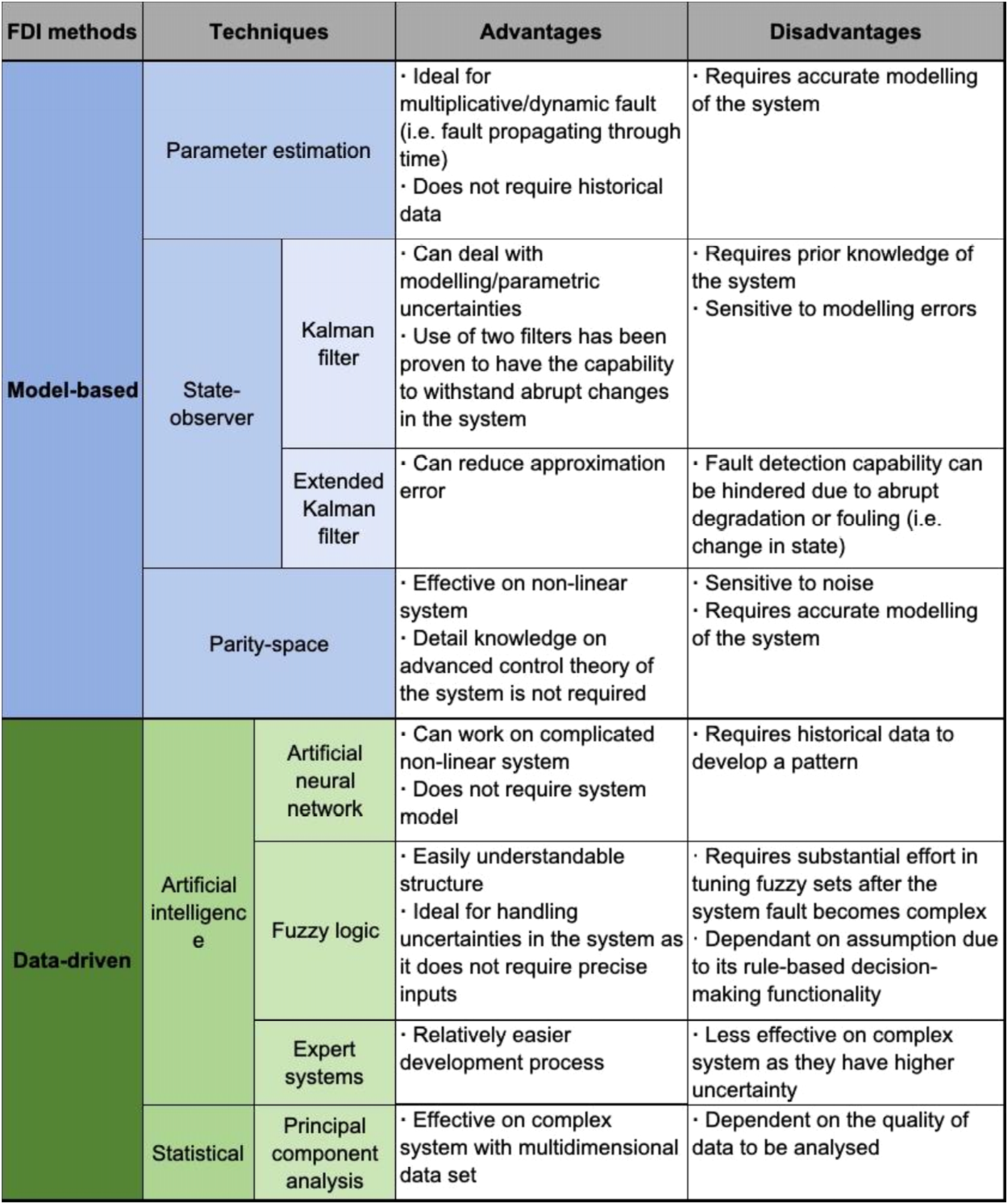
Finding 2
The open literature lacks comprehensive study on the ACM and the HPWS. The ACM can impact the overall performance of the PACK functionality as demonstrated by Santos et al. 72 where the authors conducted a thermodynamic analysis on a 3 wheel bootstrap ACM. This study validates the need for investigating the ACM in greater depth. Furthermore, an in-depth study on the humidity regulation and the diagnostic of HPWS is missing in the open literature.
System-level simulation of ECS
Complex systems such as the ECS requires system-level analysis, as there are components such as valves which can mask any fault occurrence and fault can also propagate through the system. There are only a few full-scale simulation models available for the ECS. They were mostly developed for assisting in designing a new component. These simulation models are cost-effective ways of testing a model before it goes into manufacturing and tests. As these simulation models provide a detailed understanding of the system, they can be used for diagnostic purposes. This section discusses the existing models of the ECS and their functionality.
Functional model library of the environmental control system
FLECS is an ECS modelling library programmed using MATLAB/Simulink software packages. 73 It is a project conducted by Airbus, Hamburg University of Applied Science and CeBeNetwork GmbH to construct a system-level model for the ECS. The library contains healthy models of different component blocks from BAS, PACK, valves, mixing manifold and cabin. Each of the subcomponents was taken as an individual module and were designed based on one dimensional thermodynamic equations and control system. 74
A simulation model of the ECS system was built within FLECS consisting of ducts and cabin model. After performing a comparison study with other existing simulation data, the model was verified based on temperature data collected at the supply duct inlet, PACK outlet and cabin inlet, during a test flight of Airbus A340-600. The acquired temperature data from the cabin inlet demonstrated good match. 74 The verification did not include pressure and mass flow data.
Flowmaster
Flowmaster software is commonly used in the aerospace industry for modelling. It is a 1-D thermo-fluid systems simulation that linearises model coefficients to achieve good convergence properties. Tu, Y. and Lin, G. P. 75 developed an ECS model using FlowmasterV7, which is programmed in C++ language, and the sub-block parameter method was used for mathematical modelling of the components. The work focussed mostly on developing the cabin temperature control system using expert Proportional-Integral-Derivative (PID) controller, which uses the fuzzy algorithm to adjust the PID parameters. 1 The effect of the specific humidity of the flow to model the heat exchanger (wet and dry) and ACM was considered. Both steady-state and dynamic analysis was validated experimentally with a maximum and minimum deviation of 4.3°C and 0.2°C. 75 It is to be noted that the verification did not involve pressure and mass flow readings.
Although the simulation models were primarily for design and development purposes rather than fault detection and isolation, Flowmaster simulation software has been used for fault detection for another system. Lang et al. 76 researched to detect pipe leakage based on the feature extracted from the pressure signal. Wavelet analysis was conducted for noise removal, and Least Square Twin Support Vector Machine (LSTSVM) method was used for leakage detection.
Easy5
Back in 1976, The Boeing Company developed Easy4 which later became Easy5. This software was developed for the need of having one single simulation modelling platform that can be used to create both nonlinear and linearised analysis of dynamic systems. The library was developed based on the SysteMMS a modular modelling system. Easy5 also supports additional components created using Fortran. It is only required for the user to organise the components to be placed according to the desired model and the interconnection between the components are formed by the built-in Model Generation Program. 15 This includes defining the physical driving quantities such as forces, flow rates, velocities and other variables depending on the input parameters defined by the user. It also includes an Analysis Program which permits dynamic, static, linear and nonlinear analysis of the model after all the required input parameters are set. This software can run frequency response analysis, steady-state analysis and optimal controller synthesis. 77
Easy5 was later used by Boeing for developing an aircraft ECS model for simulation analysis. Following that, Hoffman15,78 reported the use of Easy5 for simulation of F-14F fighter aircraft ECS. In another study, Gulfstream Aerospace used this software for developing the ECS model for G500 and G550 passenger jets.15,79 SAAB Group collaborated with Linköping Institute of Technology to model ECS for their fighter jet JAS39 Gripen. Fault modes identified from the historical data focusing mostly on the valve jamming was used to develop a state-observer model-based diagnostic method.15,80
Dymola
SAAB Group later migrated to Dymola as the ECS required major modifications. S-ECS system was modelled using the Modelica modelling language, which is then simulated in the simulation platform Dymola. 81 As suggested by Steinkellner 82 in a study, the model requires experimental verification and validation.
MATLAB/Simulink
For more than a decade, simulation modelling was based on arithmetic operations, integrators and transfer functions.[p.7] 83 After Easy5 simulation platform, Mathworks developed the simulation environment called Simulink around 1991, which was a major shift to the paradigm of using ordinary differential equation (ODE).
Romani and De Goes programmed a cabin temperature control model using ordinary differential equations (ODEs). The model has been validated by cabin temperature recorded under three different conditions: aircraft cooling in flight, aircraft heating in flight and pull-down scenarios. 84 The verification did not include Pressure and Mass flow readings. Although their results matched well with the data, their study lacks the modelling of the dynamic behaviour of the valves that have the potential to mask fault symptoms. 15 Furthermore, humidity has not been considered for simulation modelling.
Simscape ECS simulation for all conditions
Cranfield University IVHM Centre on a funded project by the Boeing Company developed a computationally efficient and robust simulation framework for the ECS called – Simscape ECS Simulation for All Condition (SESAC). 15 The components were constructed with simple algebraic equations based on their thermodynamic properties. SESAC is a component library which enables drag-and-drop component list that can be used to construct ECS models. This model can be used for analysing PACK performance characteristics under different operating conditions (i.e. in flight and on ground). It also supports both dry and wet simulation analysis. In comparison to Boeing’s previous simulation model Easy5, SESAC can be used for fault simulation analysis. This model has been validated against Easy5 data provided by Boeing. 85
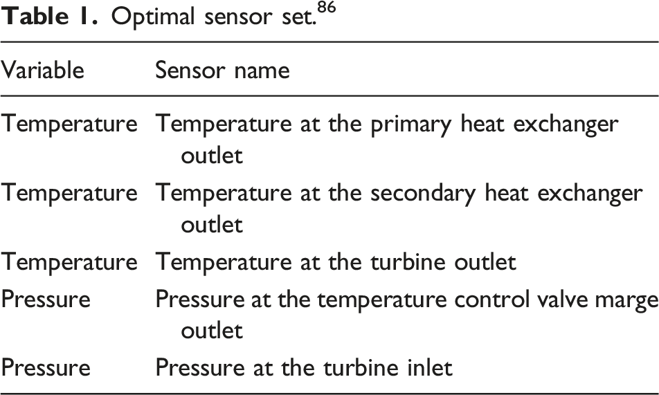
Optimal sensor set. 86
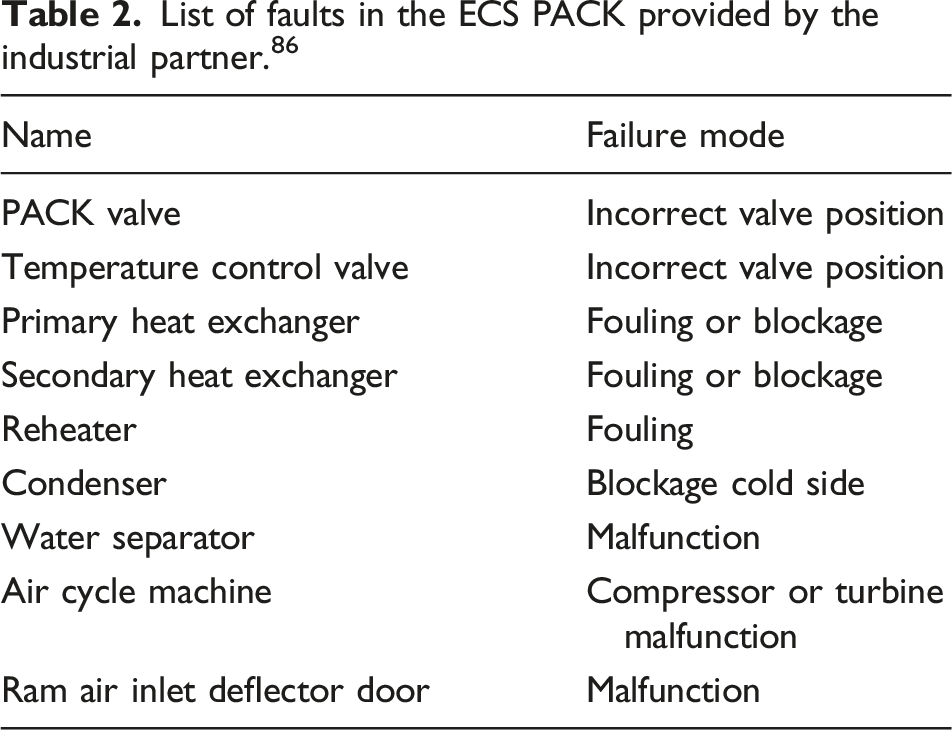
List of faults in the ECS PACK provided by the industrial partner. 86
Finding 3
The list of models identified above is summarised in Figure 8. With the exception of SESAC, the simulation models have been primarily used for design and analysis purposes. Also, in order to be used for diagnostic purposes the models require experimental verification and validation at a system level.
87
It is noted that the verification and validation of the models have not been done comprehensively. Existing ECS simulation models.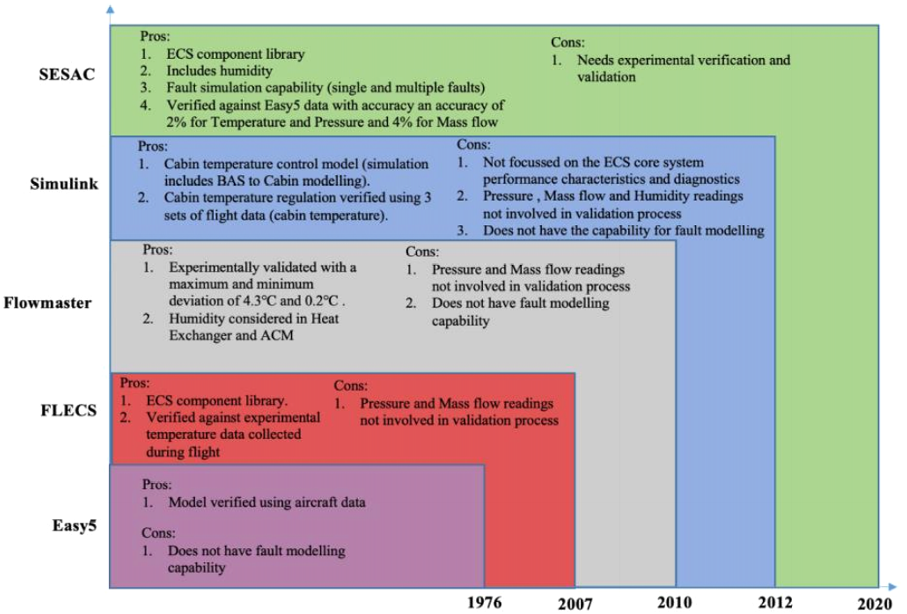
Finding 4
The emphasis on the impact of control system failure (including valve malfunction) on PACK performance at a system level is missing in the open literature.
Experimental work on the ECS diagnostics
The simulation models used for developing diagnostic rules need to be experimentally verified and validated. In addition, the sensors used for condition monitoring also require appropriate calibration and validation. A faulty model and a misplaced sensor can produce a wrong diagnostic result, which can lead towards wrong maintenance action resulting in accidents and increased maintenance costs.
Honeywell-SECAN conducted an experimental investigation to validate the performance characteristics of a new LPWS design.
88
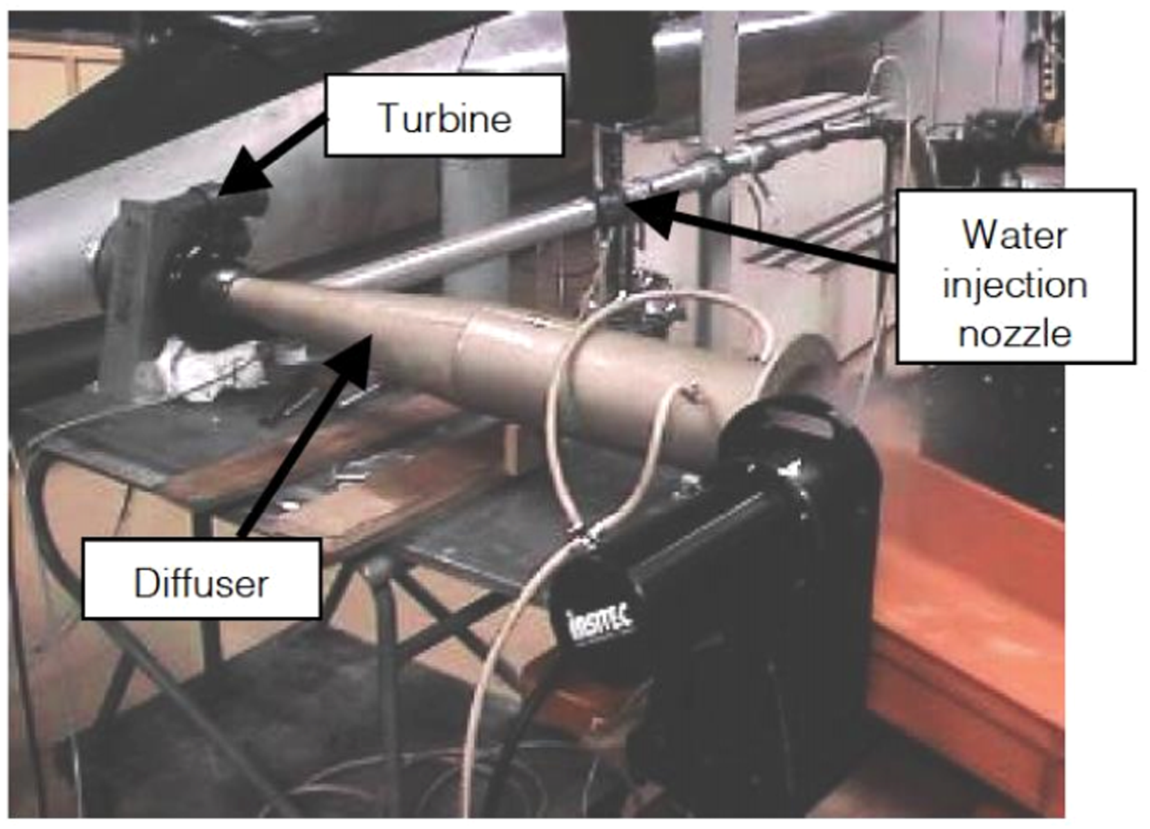
In contrast to the classical single stage water separator, a new two stage system with a coalescer followed by water separating device was designed and tested. For experimental testing, a rig was developed with a compressor air inlet, water injection nozzle, turbine, diffuser and the coalescer under test. The rig set-up is shown in Figure 9. During the experimentation, the air flow rate was set, water injected to vary the humidity value and drop size distribution and pressure drop at coalescer outlet was measured. While this was to test the coalescer, for testing the separating device, an additional aspiration system was added to the rig to collect the separated water. The amount of water recovered at the WS outlet, in the turbine and in the air stream was measured. Data collected were used to calculate the overall efficiency of the WS for design validation.
88
Rig set-up for LPWS Coalescer testing.
88
Childs et al. 89 developed a rig for testing BAE Systems fast-jet Hawk military aircraft ECS at Loughborough University. The two-wheel bootstrap cycle with LPWS ECS was set up in a lab environment. The rig was instrumented with temperature and pressure sensor, at the input and output of each component. The data collected from the rig was used to validate the 1D thermodynamic model by comparing the ECS coefficient of performance and system heat rejection. To test the diagnostic capabilities, Ram air inlet (to the SHX) was blocked, and the data collected was analysed. It was highlighted that a reduced Ram mass flow predominantly reduces the coefficient of performance of the ECS.
This rig was used to simulate faults and to conduct diagnoses at a system-level. The first failure mode analysis was on the blockage in the bleed air duct. It was identified from the research that the blockage does not drastically affect its performance until cycle mass flow falls below 75% of its unblocked state. The TCV position testing showed that TCVs would comfortably mask any failure within the system. 90 Similarly, the rig was used to analyse the effect of humidity on system performance. 90 The results indicated that humid air impacts the ECS performance characteristics particularly at the ACM. 91
In collaboration with Boeing, Esperon-Miguez et al.
92
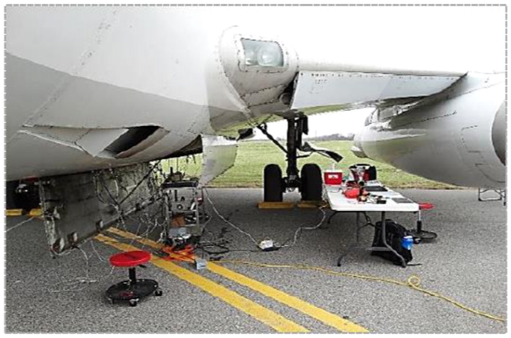
developed a thermodynamic model for the ECS capable of simulating faults in heat exchangers, valves and WS. The model has been validated using test data collected from a ground-based B737-200 aircraft which has a LPWS in the ECS. The ECS PACK was instrumented with thermocouples. The valve angles were measured using potentiometers. The rig set-up is shown in Figure 10. Two different types of experiments were conducted: healthy conditions and fault injected cases. Heat exchanger inlets were blocked using aluminium plates to reduce the effectiveness of the heat exchangers. Valves were regulated with potentiometer to fully open and fully closed scenarios. The coalescer bag was clogged without exceeding pressure differential. Using the healthy and fault injected temperature data collected the thermodynamic model was verified.
92
Experimental set-up on the B737-200.
92
Finding 5
There is a need to develop a civil aircraft in situ ECS GTF targeting temperature, pressure, mass flow and humidity data collection.
Conclusion
The aircraft ECS has been reported as one of the major drivers of unscheduled maintenance by the operators. ECS failure, resulting in sudden cabin depressurisation, has caused a number of aircraft to make emergency landings. The existing literature suggests that there is a compelling need to advance the level of scientific understanding of the ECS system operating under healthy and degraded conditions. An area of interest for the manufacturers is to investigate diagnostic approaches for detecting and isolating faults within the ECS system.
It has been identified that heat exchanger degradation has been extensively researched based on the implementation of model-based diagnostic techniques. There is very limited research available on the air cycle machine and high pressure water separator component degradation. This paper has identified different diagnostic methodologies that are applicable to the ECS system. A taxonomy of the diagnostic methodologies, including their advantages and disadvantages, are demonstrated Figure 7.
In an integrated and complex system like the ECS, fault propagates through the system and diagnosing faults correctly requires knowledge of component interdependencies. To study the interdependencies between components within a system, a system-level simulation model is required. Furthermore, the control system governing the valves needs to be well designed as they can lead to misleading PACK performance simulation analysis. The emphasis on control system is missing in the open literature.
Finally, it was found that the models available for performing ECS simulation were used primarily for design and analysis purposes. These models have been verified with very limited data and have been mostly dependant on only temperature measurements. Therefore, it is deduced that there is a compelling need for a full-scale experimental facility to perform ECS analysis under different operating conditions and to use temperature, pressure and mass flow data to verify the models.
Footnotes
Acknowledgement
The Boeing Company, as part of their collaboration with Cranfield University’s IVHM Centre, funded this work; the authors would like to thank them for their support of this project.
Declaration of conflicting interests
The author(s) declared no potential conflicts of interest with respect to the research, authorship, and/or publication of this article.
Funding
The author(s) disclosed receipt of the following financial support for the research, authorship, and/or publication of this article: This work was supported by the Boeing; IVHH-Cranfield.