
Abstract
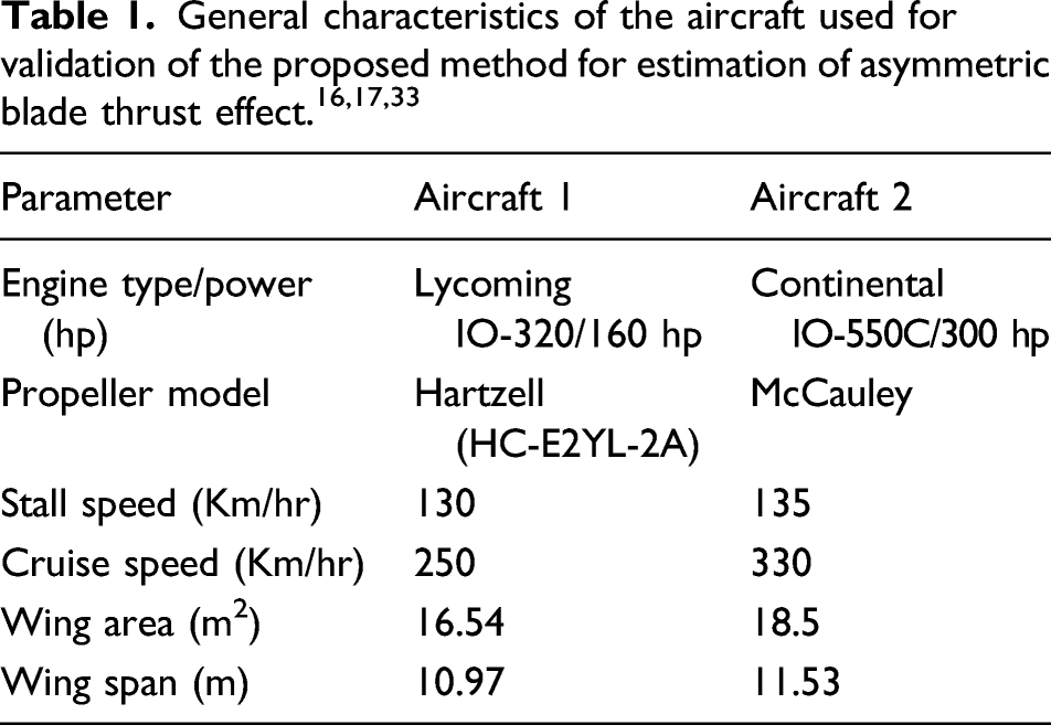
An engineering approach is presented to analyse the asymmetric blade thrust effect with the help of analytical and semi-empirical methods. It is shown that the contribution of the asymmetric blade thrust effect in the lateral-directional stability of multi-engine propeller-driven aircraft is significant particularly in critical flight conditions with one engine out of service. Also, in some cases where the engines are rotating in one direction, the asymmetric blade effect has substantial effects on the handling qualities of the aircraft even in normal flight conditions. Overall, due to the significant contribution of this phenomenon in the lateral-directional stability of propeller-driven airplanes, it is important to consider it in the design of the vertical stabilizer and rudder. The resulting analytical method has been used to determine the vertical tail incident angle and desired rudder deflection in accordance with the most critical flight condition for two different cases and validated to ensure the accuracy of the result. In this work, the aerodynamic coefficients as well as the stability and control derivatives have been predicted using analytical and semi-empirical methods validated for light aircraft.
Keywords
Introduction
Asymmetric blade thrust or the asymmetric blade effect is an aerodynamic phenomenon experienced due to the asymmetrical loading of the propeller disc. This behaviour is more significant in helicopters, rotorcraft and underwater vehicles. For propeller-driven airplanes where the propeller shaft is at a positive angle of attack, the descending blade gains more velocity comparing to the ascending one due to the fact that the descending blade moving forward into the wind and the ascending blade retreating from the wind. Hence, both the lift and drag are increased on the ascending side of the propeller and decreased on the ascending side. This variance in the velocity results in an asymmetrical thrust distribution in rotating disc which can affect the performance of the aircraft. At high angles of attack, the asymmetric blade thrust behaviour is intensified. This phenomenon can be significant in climbing flight. For multi-engine propeller-driven airplanes, this can result in a catastrophic response in one engine inoperative (OEI) conditions. For twin-engine propeller-driven aircraft with propellers rotating in the same direction (e.g. usually clockwise), this phenomenon appears in all flight conditions.1–11 It should be noted that most of the aircraft designed after the World War II era were equipped with propellers rotating in the same direction such as the Beechcraft Baron, a twin-engined derivative of the well-known Bonanza airplane currently still in production at Beechcraft company.
The propeller effects and the power contribution to the trim condition and stability of a propeller-driven airplane are crucial. Since the introduction of the airplane in 1909, this has always been of interest where a propeller produced significant lateral forces in the presence of side wind.2,6,8 Initial analytical analysis of this phenomenon was investigated by Harris 12 in 1918 where methodology for determining the resulting moment due to the side wind effect was developed. Later, Glauert expanded this investigation to determine the effect on the other stability derivatives.13,14 In the United States, studies on the propeller behaviour began in 1920s and were enhanced during World War II, when new and more powerful engines were introduced. Subsequently, most analytical methods were based on classic linear momentum theory. 15 Later in 1972, the National Aeronautics and Space Administration (NASA) investigated the aerodynamic coefficients and stability and control derivatives of twin-engine propeller-driven airplanes resulting in new methodology to determine aerodynamic forces and moments due to the propeller in power-on conditions.16,17 Despite the outstanding results, several assumptions limit the ability of the methodology to provide enough information about advanced aircraft. These assumptions include untwisted wings, all-movable control surfaces and simple flaps. Recently, several studies have enhanced semi-empirical methods to investigate the aerodynamic characteristics of more sophisticated propeller-driven airplanes and the propeller effects on the handling quality.18–24 These studies attempted to modify and combine state-of-the-art analytical procedures and design data compendia in compatible methods to compensate for the limitations of the previous methods.
Generally, in single-engine light propeller-driven airplanes, in order to decrease the propeller effects, a small side angle for the entire engine package can be introduced (i.e. typically to the right-hand side for a clockwise rotating propeller from a pilot field of view). However, in the case of twin-engine propeller-driven airplanes with propellers rotating in the same direction (i.e. clockwise from a pilot viewpoint), using a side angle results in an asymmetry in the design. This is typically avoided due to unwanted side effects. Consequently, in order to compensate for the propeller effects in these types of aircraft, usually a very small permanent deflection (∼1°) is built into the fixed part of the vertical stabilizer. 25
With respect to Figure 1(a), when the disc blade bends towards the flight path, the ascending blade faces a lower angle of attack in comparison with the descending blade. Hence, in Figure 1, the corresponding angle for Asymmetric blade thrust effect (a) in the presence of an angle of attack (b) in a twin-engine propeller-driven aircraft while flying with a positive angle of attack.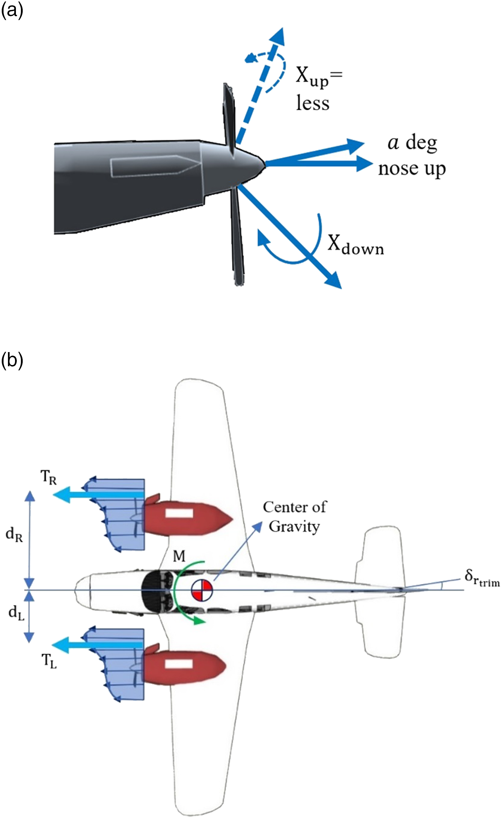
The asymmetric blade thrust effect is difficult to isolate since the effect is often swamped by other effects such as the helical prop wash and twisted lift. For propeller-driven airplanes in climbing flight, the combination of low airspeed, high angle of attack and high power makes the asymmetric blade thrust effect more pronounced.
Asymmetric blade thrust appears when the blade disc is not perpendicular to the incoming airflow. 26 When the propeller shaft is at a positive angle of attack, the descending blade of the right-hand side engine produces more thrust than the ascending blade. Consequently, the amount of yaw torque produced by the left-hand side engine over the centre of gravity of the aircraft would be lower than the amount produced by the right-hand side engine (Figure 1(b))). This means that the asymmetric blade thrust can result in a yaw to the left. In order to compensate this yaw, the pilot needs to deflect the rudder of the aircraft to the right-hand side. 27
Critical engine
Due to the asymmetric disc loading, the moment contributions of the engines are not balanced for the case of twin aircraft with engines that rotate in the same direction. If an engine failure occurs, the effects are different depending on which engine experienced the failure. It is therefore important to consider which engine is the critical engine. The critical engine is defined as ‘the engine whose failure would most adversely affect the performance or handling qualities of the aircraft 28 ’. In order to determine the critical engine, four factors need to be considered. These include the asymmetric blade thrust, accelerated slipstream, spiralling slipstream and torque.
With respect to the twin-engine propeller-driven airplane shown in Figure 2(a) with engines rotating in the same direction (e.g. clockwise from the pilot viewpoint), when one engine is out of service in the climb flight condition, the aircraft is facing a high angle of attack and high power. Consequently, asymmetric blade thrust effect is significant in this situation, and the aircraft tends to yaw to the direction of the critical engine. In order to compensate this and to keep the aircraft in a safe situation, one has to deflect the rudder surface to the opposite side of the critical engine. With respect to Figures 1(b) and 2(a), failure of the left engine will cause more loss of the directional stability than loss of the right engine because the related thrust to the right engine has a longer arm from the centre of gravity.
29
Hence, with respect to the asymmetric blade thrust effect, failure of the left engine is more critical. (a) Asymmetric blade thrust effect in critical flight condition for a twin-engine propeller-driven aircraft; (b) schematic description of the accelerated slipstream for a twin-engine propeller-driven aircraft.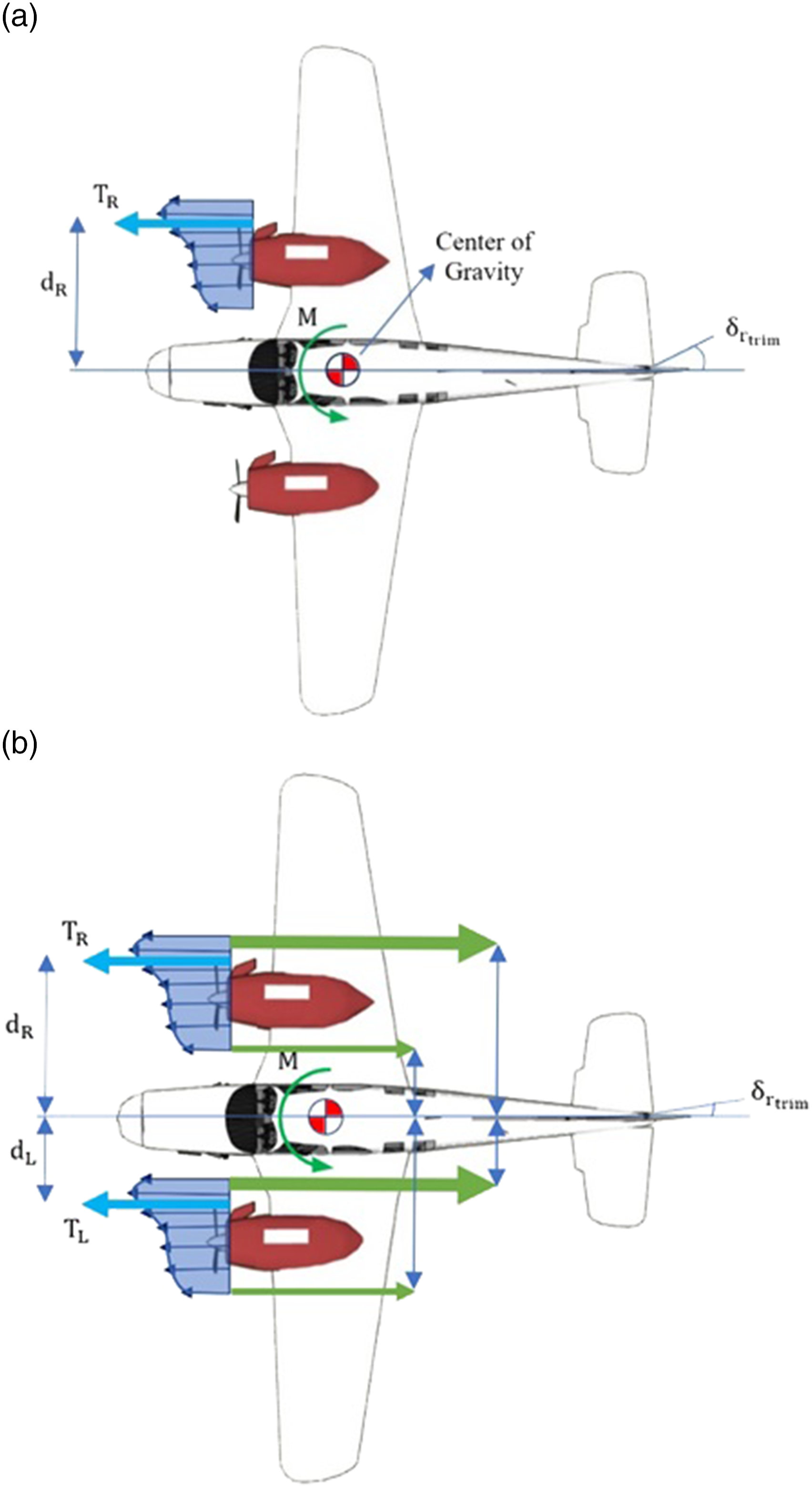
As a result of the asymmetric blade thrust, stronger induced lift is produced by the prop wash on the right-hand side of the right engine comparing to the induced lift produced on the left-hand side of the left engine. So, as can be seen in Figure 2(b), failure of the left engine will result in a substantial moment rolling the aircraft to the left. Also, in case of a left engine failure, less negative lift will be produced by the tail resulting in a pitch down of the entire aircraft. Therefore, failure of the left engine will cause a roll to the left and a pitch down.
As shown in Figure 3(a), the spiralling slipstream from the left engine pushes the vertical tail from the left-hand side causing yaw towards the left. For a right engine failure, a portion of the yaw towards right due to the left engine will be compensated by the yaw towards the left due to the spiralling slipstream on the vertical tail. A failure of the left engine will result in more loss of directional control due to the absence of the spiralling slipstream effect on the vertical tail producing the opposite yaw. Therefore, with respect to the spiralling slipstream, failure of the left engine is more critical. Schematic description of (a) the spiralling slipstream for a twin-engine propeller-driven aircraft and (b) the accelerated slipstream for a twin-engine propeller-driven aircraft.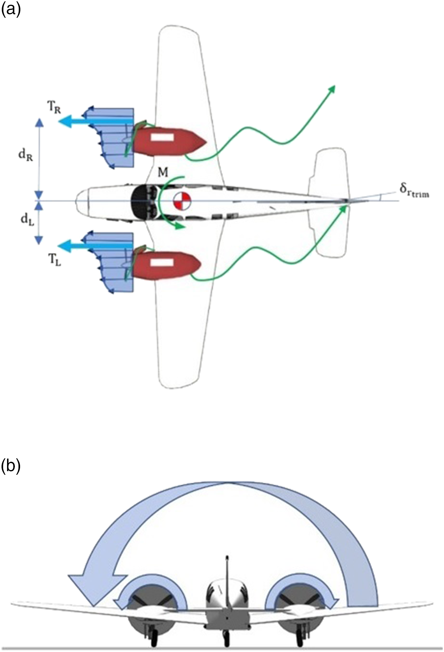
Additionally, the clockwise torque of the propeller will result in a counter-clockwise torque about airplane as shown in Figure 3(b)), causing a left rolling tendency of the entire airplane. In case of a right engine failure, the left roll tendency will resist the right roll tendency towards the inoperative engine caused by the asymmetric blade thrust, somewhat mitigating the destabilizing effects of the engine failure. Conversely, failure of the left engine will result in an additional left roll tendency which will be added to the left turning tendency caused by the asymmetric blade thrust. Hence, directional control is more critically affected by a left engine failure. Considering these factors together shows that the left-hand side engine is the critical engine for a conventional twin-engine propeller-driven aircraft with clockwise rotating propellers.
This research builds on previous work in which an enhanced semi-empirical method, called NAMAYEH, was developed to calculate longitudinal and lateral-directional stability and control derivatives of light airplanes.17–24 In this study, an engineering method is provided to perform vertical tail sizing considering stability and control including the asymmetrical blade thrust effects. A case study was developed considering a twin-engined aircraft equipped with propellers rotating in the clockwise direction with respect to the pilot’s field of view. In this case, the descending blade of the right-hand side engine has a larger arm compared to the left-hand side engine. Consequently, the produced torque in each side will be different (e.g. right-hand side more than left-hand side in this case), and the aircraft tends to yaw to the left. In the following, the physics behind this phenomenon is discussed, and results for two different cases are provided in detail.
Physics of the method
In order to model propeller effects, it is assumed that the propeller rotates as a disc perpendicular to the ground. In the first step, it is assumed that there is no side wind, which is added to the model in subsequent steps.
26
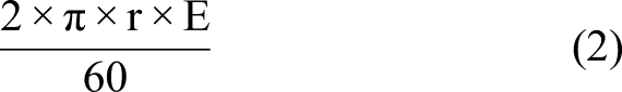
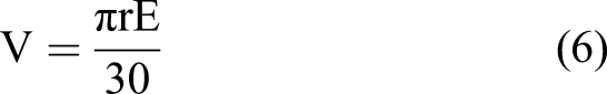
Considering a point with the distance of r from the propeller hub rotating with the rotational velocity of E (i.e. rpm for an engine), the corresponding linear velocity of the assumed point is as follows
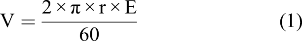
Given the assumptions, as the side wind is mainly from the propeller movement, the linear velocity relation provided in equation (1) is the velocity seen by the propeller. In the next step, the effect of the side wind is added to the model. It can be assumed that the disc is still in the same situation to the ground with a new rolling to the forward with the same velocity or it can be assumed that the nose of the aircraft is completely horizontally levelled. Assuming that the side wind is acting with the velocity of A relative to the aircraft, a point with a distance of r from the propeller hub has a movement in three different dimensions. This movement is rotational in rotating propeller disc and towards forward to counter the side wind. Integration of these two results in the movement of this point to the outside of the propeller. Consider the location of this point on the propeller disc at the 9 o’clock and the 3 o’clock positions for further calculations. At the 3 o’clock position, the assumed point has a normal down going motion of
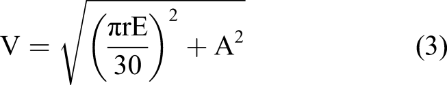
While the propeller is moving to the lower position, more side wind will be seen on the assumed point. However, there is also a forward velocity for the point. The sum of both velocities will result in the velocity equation with the side wind contribution as follows
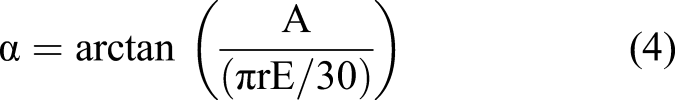
As mentioned, the assumed point is moving down and forward. So, a side wind is being seen to move forward from the descending path. Here, the angle that the side wind creates with the descending path is called α and can be calculated as follows
Consequently, with the new assumptions, the corresponding value for the angle of attack will also change. This value with respect to the side wind effect can be presented as follows

For the case at the 9 o’clock position, the results will be similar as disc is still perpendicular. However, the resulting velocity vector will be inside and forward as shown in Figure 1(a).
So far, the analysis on the asymmetric blade thrust has been considered symmetric. In the following, the nose pitch-up effect is considered in the level flight condition which will result in an up-ward movement for the rotating propeller whereby the tip of the propeller moves back and the root moves forward. In this case, another parameter is required to determine the backward movement of the propeller. This parameter is represented as the angle ρ. In this situation, the movement of the assumed point is of interest to find the velocity and direction of the point in response to the asymmetric blade thrust effect.
The movement of the assumed rotating point of the propeller relative to the aircraft movement is not perpendicular. The movement due to propeller rotation is evaluated first and divided into vertical and horizontal components. Similar to the previous case, the velocity due to the rotation of the propeller can be calculated as follows from the point at the 3 o’clock position
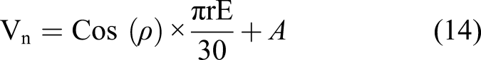
This time, the angle of ρ has also been considered in the calculations and can be expressed as follows for the normal component of the velocity
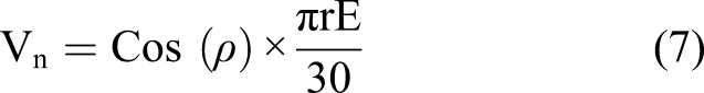

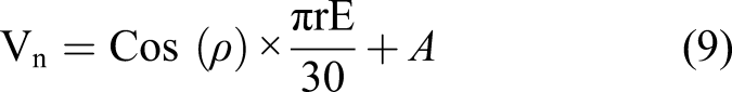
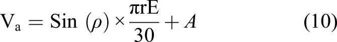
Now adding the side wind effect to equations (7) and (8) results in relations for the normal and axial components of the velocity vector and can be represented by equations (9) and (10) as follows
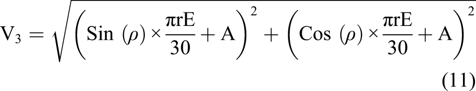
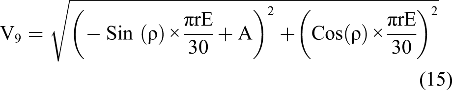
Consequently, the corresponding velocity for the assumed point on the rotating propeller can be calculated by
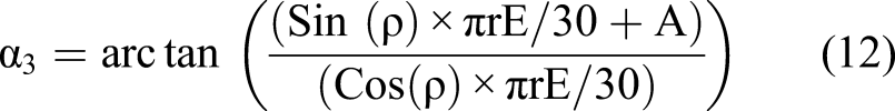
In order to validate the results, another factor that is needed to be recalculated in accordance with the new assumptions is the path that will be seen by the point relative to the side wind. This can be expressed by equation (12) as follows
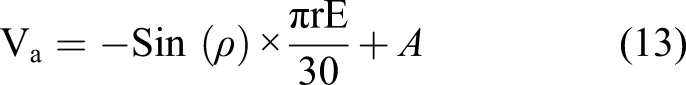
At the 9 o’clock position, the propeller is moving up and backward.
26
Here, the axial component can be expressed by equation (13) as follows
The main difference is that this time the propeller is ascending. The corresponding velocity and path angle can be calculated by
In this study, the induced flow input from other sections of the propeller blade is neglected in the calculations. The assumption is valid as the angular speed is much larger than the induced velocity component. Additionally, considering the induced velocity in the calculations would increase the complexity of the method as it is a function of the thrust produced which is in turn resulted because of the side effects produced by the induced velocity itself. The velocity equations would become non-linear and greatly increase the complexity of the method. 30
Given the two velocity values and path angles at the 3 o’clock and 9 o’clock positions, the thrust difference at each side of the aircraft can be determined. In order to study the behaviour of a rotating propeller, thrust produced due to propeller rotation can be considered as a lift force to the axial direction rather than normal direction. The following lift coefficient equation can be used to determine the thrust contribution
31

Therefore, given the aerofoil used in the propeller and the path angle, the asymmetric blade thrust contribution can be estimated in the generated force using the corresponding velocities of each point. The resulting thrust equation can be expressed as follows


With respect to equation (19) and having the thrust contribution of each engine, the moment at each side can be determined. Finally, given the difference in moments, the required vertical tail incidence angle or rudder deflection can be calculated. Figure 4 schematically describes the thrust distribution at each side of a twin-engine propeller-driven aircraft with clockwise rotating engines and the corresponding arms related to the 3 o’clock and 9 o’clock position for each engine. Thrust distribution at each side of a twin-engine aircraft with clockwise rotating engines and the corresponding arms related to the 3 o’clock and 9 o’clock position.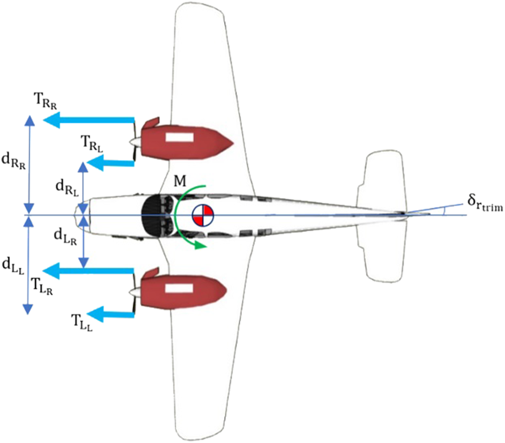
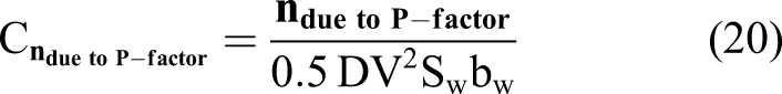
It should be noted that at each moment, the thrust contribution of each engine at the right-hand side and left-hand side will be different. Having the thrust values, the corresponding non-dimensional force coefficient due to the asymmetric blade thrust can be expressed based on the original side force coefficient
30
by equation (20) as follows
Given the corresponding force due to the asymmetric blade thrust, the required vertical tail incidence angle and rudder deflection can be determined based on different flight conditions.
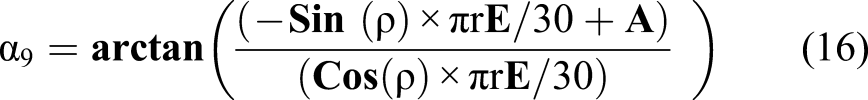
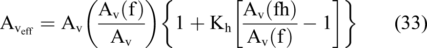
The general equation for

In the level flight condition,

In order to calculate the rolling moment due to rudder deflection, it is necessary to calculate the corresponding side force due to rudder deflection, Rudder-span factor as a function of the taper ratio, (a) Rudder-chord factor as a function of the vertical tail aspect ratio, 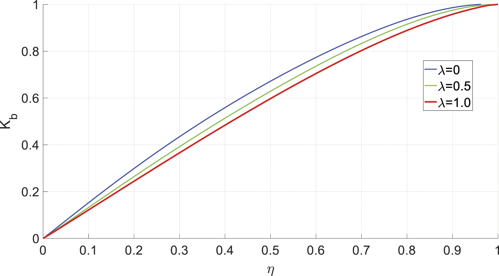
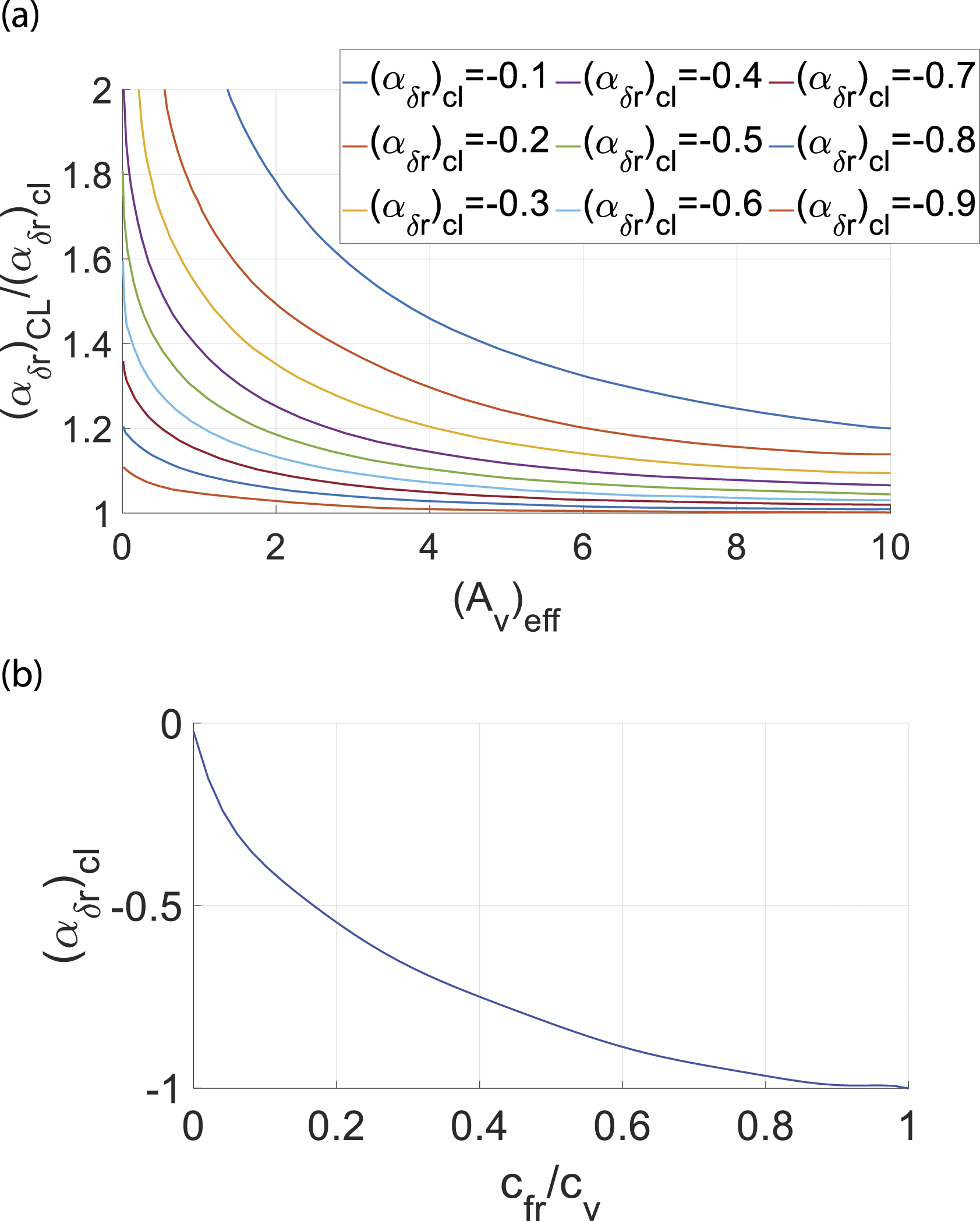
(a) 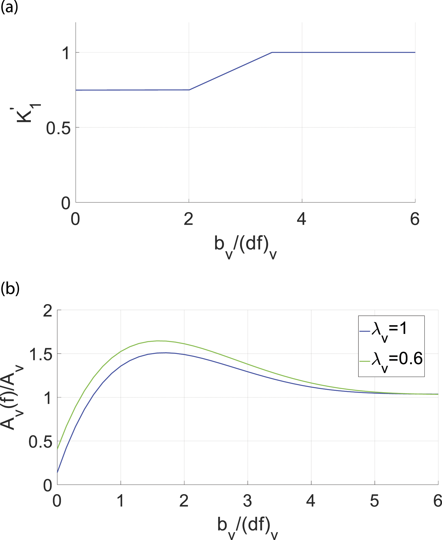
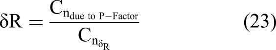
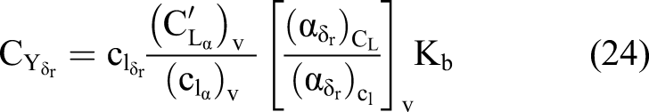
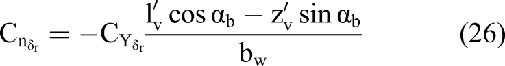
Using equation (24), the yawing moment due to the rudder deflection can be calculated in accordance with the stability axes system as follows
31
The asymmetric blade thrust effect appears in the cruise flight condition as well where the trim angle of attack is not zero. For cases where the asymmetric blade thrust effect is very pronounced due to high thrust from powerful engines, the required rudder deflection can be incorporated into the design as a permanent vertical tail incidence. The required incidence to neutralize the asymmetric propeller effect is given in equations (27) and (28)

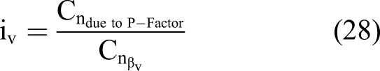
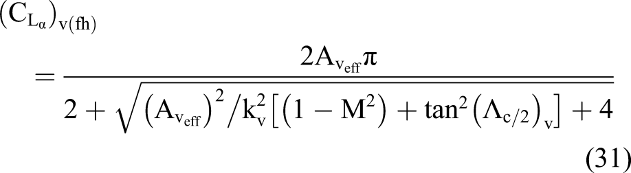
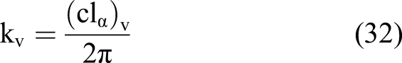
In order to determine the corresponding vertical tail incidence angle, the required
Equations (28)–(33)
31
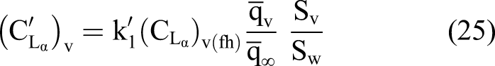
are used to calculate the contribution of the vertical tail to the side force (a) 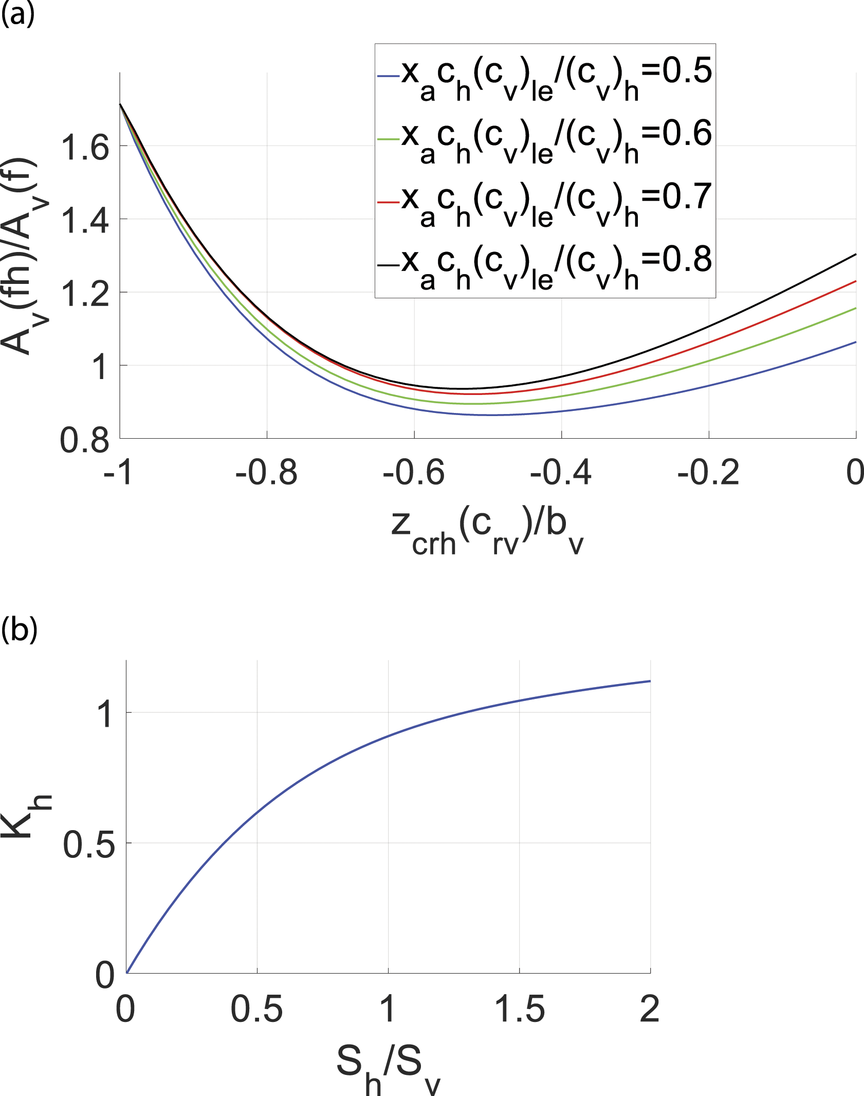
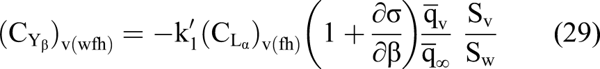
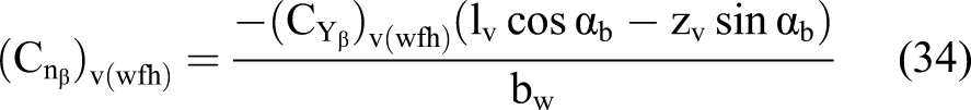
Given the side force variation with sideslip angle, the vertical tail contribution in the lateral stability of the aircraft in presence of the wing, fuselage and horizontal tail can be estimated using equation (34) as follows
31
In the following, rudder deflection sizing and vertical tail incidence angle sizing scenarios are determined at the most adverse flight conditions.
Validation and results
Rudder deflection sizing and results
The most adverse flight condition was considered in order to size the required rudder deflection for the aircraft. The highest rudder deflection for a multi-engine aircraft is required in the one engine inoperative (OEI) condition when the failed engine is the critical one. As discussed earlier, for a twin-engine propeller-driven aircraft with clockwise rotating propellers, the left-hand side engine is the critical engine. The most crucial condition for an OEI situation is when the aircraft is flying in the climb condition at the minimum control speed (e.g.
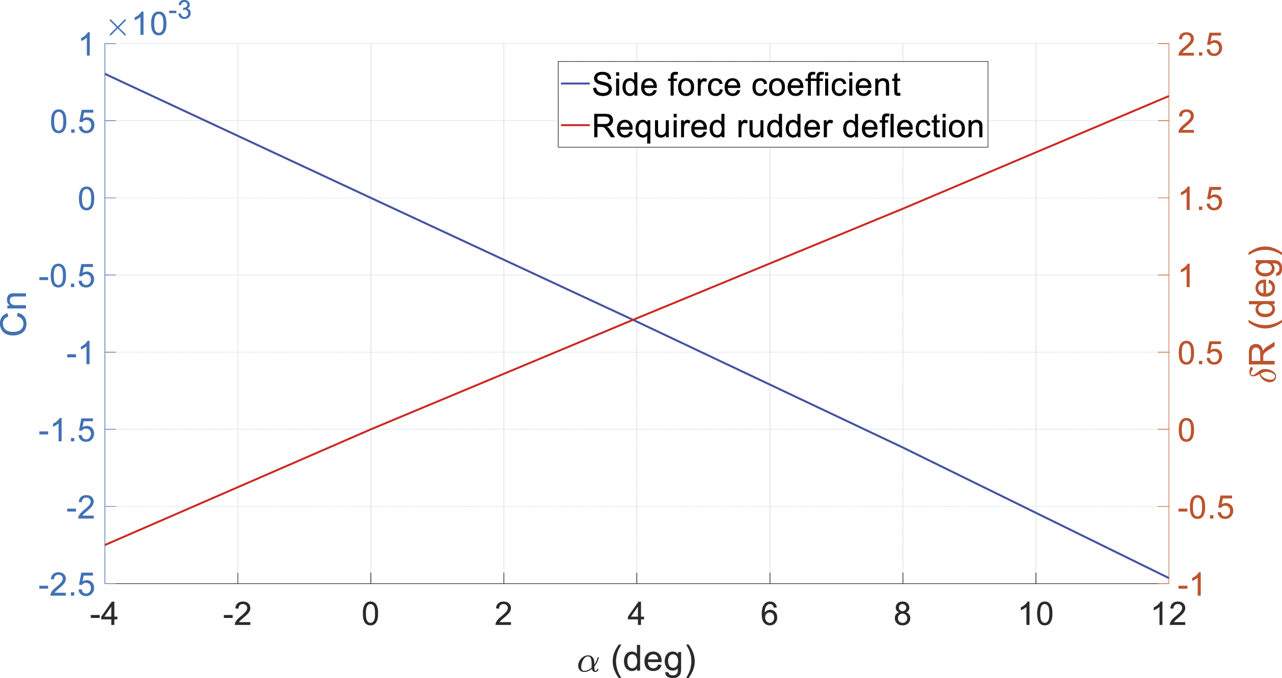
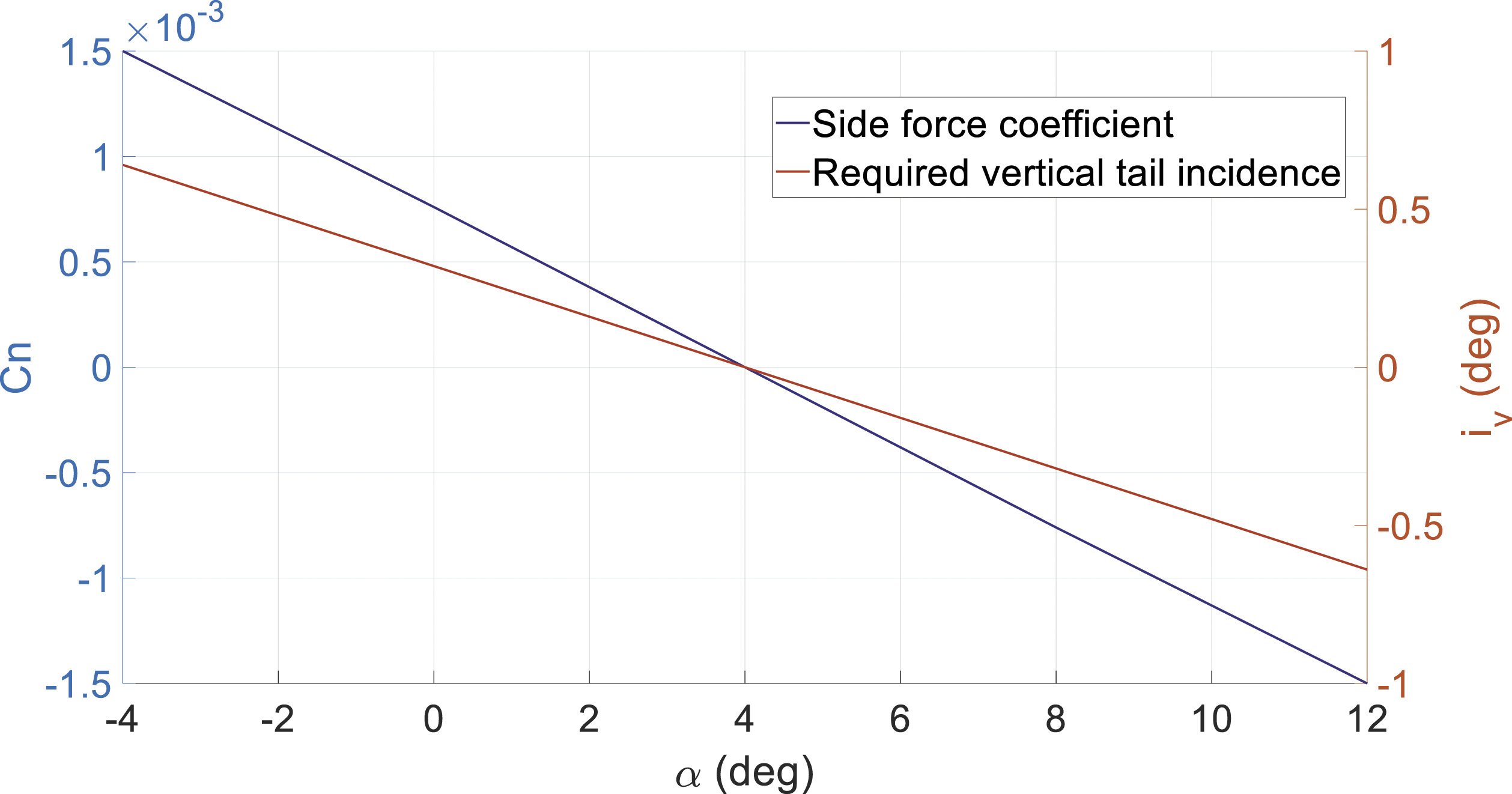
Side force coefficient for various angle of attack and the required rudder for compensation while both engines operating.
Side force coefficient for various angle of attack and the required rudder for compensation while the aircraft is flying with one engine inoperative at minimum control speed.
As shown in Figure 10, the required rudder deflection based on the stall angle of the aircraft at 12° is equal to 22°, and the same value has been proposed for this aircraft in Refs. [16,17]. With respect to Figure 10, the difference between the required rudder deflection at the zero angle of attack which denotes zero effect from asymmetric blade thrust and the highest angle of attack at 12° before the stall condition with the highest asymmetric blade thrust contribution is ∼4°. Accordingly, the asymmetric blade thrust effect considering the OEI condition in climb is significant and a designer needs to be aware of this in early design stages of a multi-engine propeller-driven aircraft.
In the next step, vertical tail incidence sizing is calculated at the cruise flight condition and is compared with existing aircraft. A larger aircraft with higher power is considered.
Vertical tail incident sizing and results
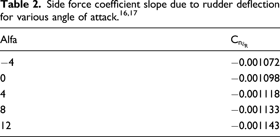
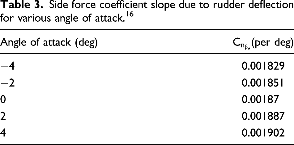
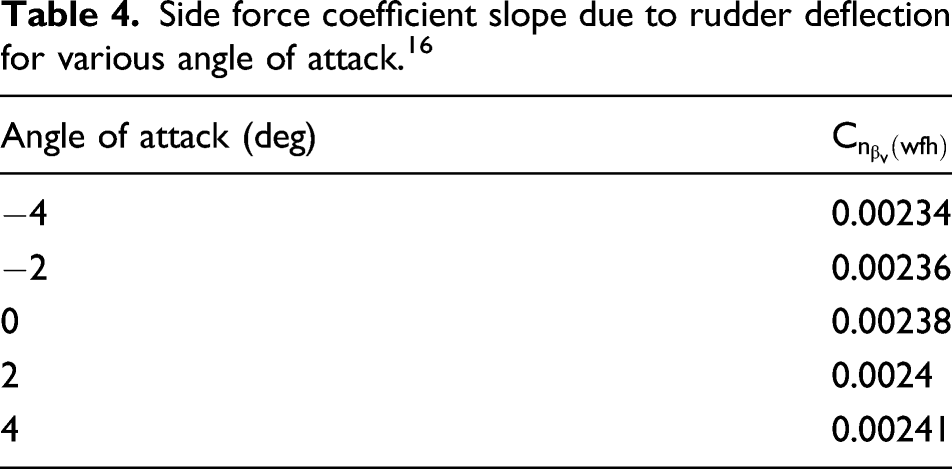
Side force coefficient slope due to rudder deflection for various angle of attack. 16
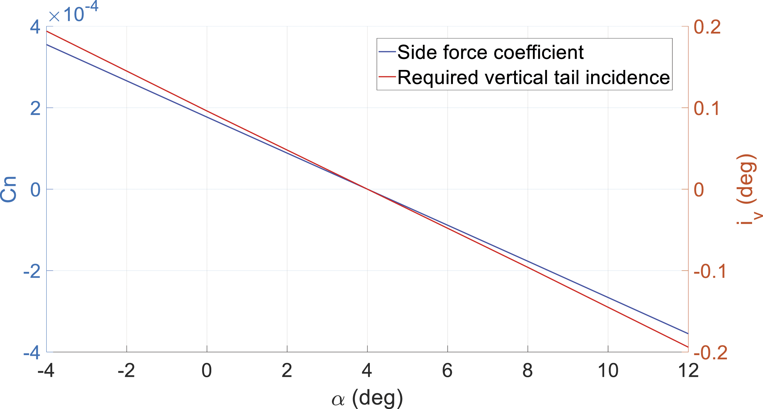
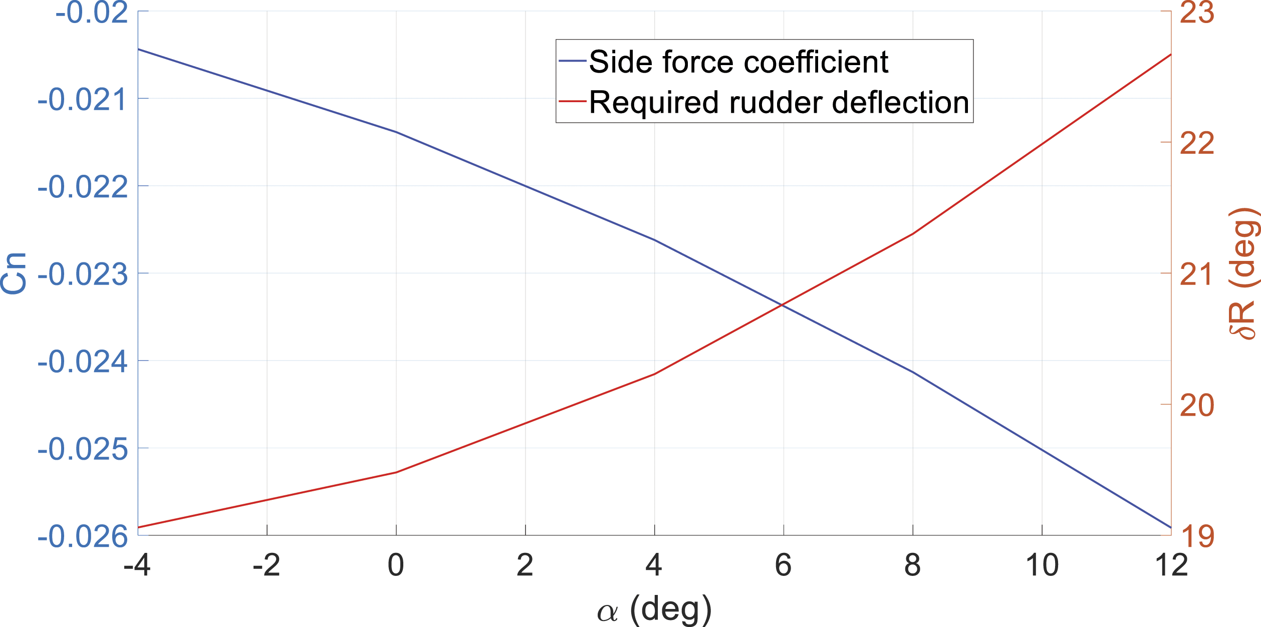
Side force coefficient for various angle of attack and the required rudder for compensation while both engines operating.
In order to size the required incidence angle of the vertical tail, one can refer to the trim flight condition in the cruise flight. For the case of aircraft 1, as this angle is equal to 1.38, the corresponding value for the angle of incidence will be very small and equal to 0.066°. As aircraft 1 uses a zero-incidence angle for the vertical tail, one can say that for this particular aircraft the incidence angle can be considered equal to zero.16,17 Therefore, for aircraft 1 in cruise flight condition, the pilot can compensate the corresponding side force due to the asymmetric blade thrust using a small deflection of the rudder trim tab control surface.
Side force coefficient slope due to rudder deflection for various angle of attack. 16
Side force coefficient for various angle of attack and the required rudder for compensation while both engines operating.
Given these results for the side force coefficient and the corresponding trim angle of 2° for aircraft 2, the required incidence angle for the vertical tail can be determined. This angle for aircraft 2 is equal to 0.32° to the right. The proposed angle for aircraft 2 is also comparable for an existing Baron G58 aircraft which has almost the same characteristics and using a small incidence angle for the vertical tail. 34
Conclusion
A method for determining the asymmetric blade thrust effect is presented for propeller-driven airplanes, and methodology for determining the vertical tail incidence and rudder deflection due to the effect is provided. The proposed method was used to evaluate and size vertical tail incidence and required rudder deflection for two different airplanes. As a result, it was shown that for a typical propeller-driven aircraft several factors including propeller type, engine power, engine position and aircraft trim angle play key roles in vertical tail incidence sizing. It was determined, for a twin-engine airplane with 180 hp power per engine, that the corresponding vertical tail incidence angle in cruise flight condition is very small, requiring only a small trim tab angle to counter the asymmetric blade thrust effect. However, for the second case where the aircraft was equipped with more powerful engines having 300 hp each, the corresponding tab deflection angle to cancel the asymmetric blade thrust effect in this case was equal to 5°. In this circumstance, the designers may wish to consider a permanent vertical tail incidence angle of 0.32°. Also, in this study the maximum required rudder deflection for the first aircraft was studied in the critical flight condition to validate the proposed method. It was shown that the asymmetric blade thrust can increase the required rudder deflection in OEI condition in climb up to ∼4° for the aircraft. The estimated value for the required rudder deflection matches the value proposed for this aircraft from the manufacturer.
Footnotes
Declaration of conflicting interests
The author(s) declared no potential conflicts of interest with respect to the research, authorship, and/or publication of this article.
Funding
The author(s) disclosed receipt of the following financial support for the research, authorship, and/or publication of this article: This work was supported by Mitacs through the Mitacs Accelerate Program (reference number: IT16648) and Columbiad Launch Services Inc.