
Abstract
The Moon Village and similar concepts are strongly reliant on in situ resource utilisation (ISRU). There is great interest in harvesting solar power using locally leveraged in situ resources as an essential facet of in situ infrastructure. Traditionally, silicon-based photovoltaic cells have been assumed, preferably manufactured in situ using a 3D printing rover, but there are major difficulties with such scenarios. Solar cells require pre-processing of regolith and solar cell manufacture. We present an alternative lunar resource leveraged-solar power production system on the Moon which can yield high conversion efficiencies – solar Fresnel lens-thermionic conversion. The thermionic vacuum tube is constructed from lunar-derived materials and NiFe asteroidal ores on the Moon. Given that the majority of energy required for ISRU is thermal, thermionic conversion exploits this energy source directly. Silicates such as anorthite can be treated with acid to yield alumina and silicic acid in solution from which pure silica can be precipitated. Pure silica when heated to high temperature yields fused silica glass which is transparent – fused silica glass may be employed to manufacture Fresnel lenses and/or mirrors. Both silica and alumina may be input to the Metalysis Fray Farthing Chen Cambridge electrolytic process to yield near pure Si and near pure Al, respectively.
Keywords
Introduction
To maximise sustainability in our imminent ventures to the Moon, it will become essential to maximise our utilisation of local resources on the Moon while minimising the resources required to be supplied from Earth. In terms of lunar infrastructure development, it will be essential to build suitable energy generation and energy storage facilities on the Moon for the Moon from the Moon. Launch from the lunar surface to geostationary equatorial orbit (GEO) about Earth requires a delta-v of 3.3 km/s placing a premium on sourcing propellant/oxidiser from lunar resources to return cargo and humans to Earth to reduce the costs for human missions.
Most in situ resource utilisation (ISRU) scenarios envisage extracting volatiles – water primarily – for life support consumables, fuel cells and propellant/oxidiser. Water can be electrolysed into hydrogen propellant and oxygen. Ferrimagnetic magnetite (Fe3O4) with its Fe2+ in nanoparticle form is a potentially useful material derivable from lunar ilmenite – solar energy and the Fe3O4/FeO redox pair offer the prospect of splitting water for the production of hydrogen efficiently 1 but most scenarios envisage electrolytic splitting into hydrogen and oxygen. To be sure, propellant and oxidiser constitutes the lion’s share of mass required to indulge in space exploration. There is little doubt that production of in situ consumables will have the greatest impact on human mission costs. Furthermore, consumables require minimal processing following extraction but this advantage is offset by the complexities involved in mining at the lunar poles. It has been suggested that water ice may be mined from permanently shadowed craters (where the temperatures are ∼40 K) at the lunar poles. The infrastructure required to implement this will be immense. It has been proposed that giant mirrors mounted at peaks of eternal light can beam sunlight into the dark craters to heat the water ice into vapour which is recovered under a transparent film onto which it condenses and is recovered, that is, a solar still. 2 The beamed solar energy may also be exploited by in situ photovoltaic arrays to electrically split the water into hydrogen/oxygen. The evolved gases must then be compressed and stored cryogenically in LH2/LOX tankage of lunar launchers.
Self-sufficiency has been the primary motivation to reduce reliance on the supply of consumables from Earth. However, there is a trade that must be performed in determining the relative mix between solar energy and water as fuel source on the Moon – clearly, solar energy is an abundant renewable resource while water (for hydrogen/oxygen) as a limited resource is not. This favours the adoption of direct solar energy consumption over fuel/oxidant consumption, for example, electromagnetic launchers 3 that can substitute for cryogenic hydrogen/oxygen-fuelled launchers from the lunar surface. We suggest that mining the Moon for water to be burned as propellant/oxidiser is wasteful of scarce resources and is unsustainable. 4 Furthermore, the creation of a lunar infrastructure robotically – without astronauts initially – with a wider exploitation of lunar resources could encourage commercial exploitation by reducing the barriers to business. Large-scale space manufacturing is a highly desirable goal for supporting both space exploration and terrestrial markets, for example, in the provision of solar energy through solar power satellites (SPS). 5 Indeed, the lunar surface may be used as a mounting platform for a solar power system from where it could beam power to Earth from the Moon across the 384,000 km distance.6,7 Six lunar power stations (LPS) located on the nearside residing along the eastern and western limbs of the Moon can collect 130 TW of solar energy for the delivery of 20 TW of electrical energy on Earth (assuming a total end-to-end efficiency of 15%). They provide the total equivalent of a 174 km diameter solar array area (95,900 km2 area). Solar ridges may be angled to the sun according to lunar latitude. Conversion to microwave is accomplished through magnetrons which is a microwave amplifier vacuum tube. A minimum of three Earth rectenna stations at 120o apart are required due to Earth’s spin to ensure continuous power generation. To provide continuous full power load, auxiliary reflectors are required in orbit around the Moon (20 TW). Fleets of microwave reflectors in high inclination eccentric low Earth orbits can direct the microwave transmissions from the Moon to the Earth’s rectennas on its nightside. The lunar power station eliminates issues with structural stability of large structures implied by large SPS. The 2-week lunar night is the most significant complication. Approaches to obviate this include the use of solar reflectors (lunettas) in lunar orbit to project solar energy to the lunar surface. A lunar system could deliver 20 TW electricity to 100,000 km2 of microwave rectenna receivers which could be implemented over deserts or offshore. A more efficient approach would be to manufacture SPS on the Moon which are launched into GEO orbit from the lunar surface.5,8 The employment of swarms of small SPS eliminates the problem of structural stability of large Earth orbiting structures and eliminates the requirement of lunar orbiting solar relay satellites and Earth orbiting microwave relays required from LPS.
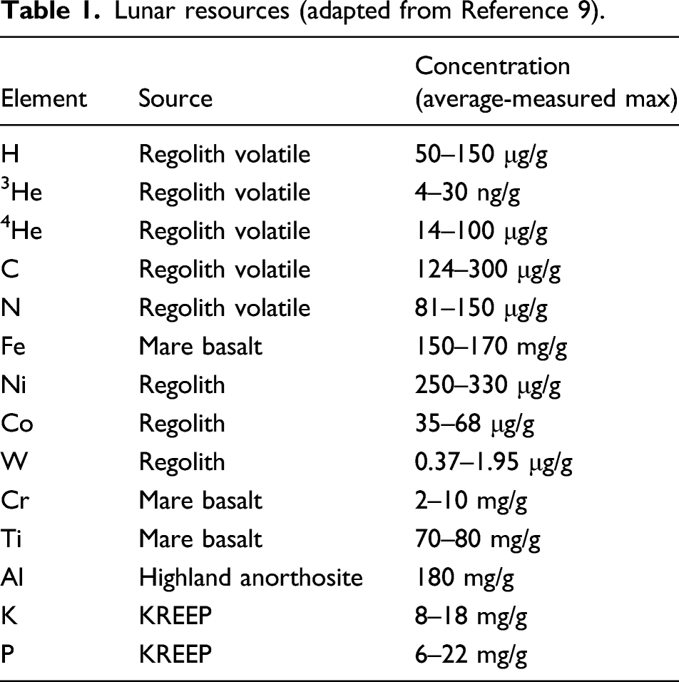
Lunar resources (adapted from Reference 9).
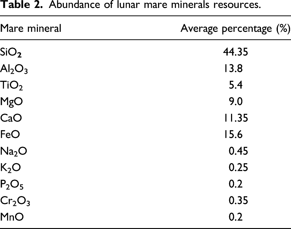
Abundance of lunar mare minerals resources.
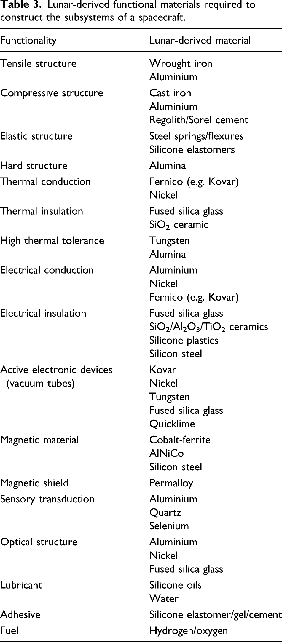
Lunar-derived functional materials required to construct the subsystems of a spacecraft.
This requires a ‘satisficing’ engineering philosophy driven by local material accessibility rather than the more traditional optimal engineering philosophy characteristic of Earth. On the Moon, we must literally build everything from the ground up. To that end, we have devised a lunar industrial ecology that extracts these metals and oxides from lunar minerals as our material resource base supplemented with more exotic materials from asteroidal resources on the Moon (see Supplementary Appendix). Our lunar in situ manufacturing ecology minimises waste – this also minimises superfluous energy consumption.
As we venture towards revisiting the Moon to create the ‘Moon Village’, the supply of low-cost energy will be a major aspect of infrastructure support for such a village. A critical requirement for supporting a human base on the Moon or Mars will be a sustainable and reliable source of power. A lunar base requires ∼100 kW of power rising as to as much as ∼MW to support a full mining and manufacturing facility. To keep both capital and operational costs as low as possible, this energy must be supplied locally on the Moon supported by transduction methods that can also be leveraged locally on the Moon. To that end, we address the most appropriate modes of energy generation, conversion and storage that can be leveraged from lunar resources. Although solar photovoltaics in conjunction with chemical batteries/fuel cells are de facto standard spacecraft technologies for energy generation, they would be challenging to manufacture in situ and are not optimal solutions for lunar base deployment which suffers two-week long eclipses. Although solar photovoltaic energy farms have been proposed, the manufacture of solar cell quality pn junctions using lunar material is problematic. The commonest energy sources proposed for supporting a lunar base are nuclear reactor with Stirling cycle power conversion and solar photovoltaic array in conjunction with energy storage for the lunar night. Energy storage options include batteries, fuel cells or flywheels. The requirement for energy storage can be reduced by siting solar energy generators at peaks of eternal light (such as the Malapert mountains near the south pole). Solar energy can be exploited in other ways – as thermal sources via solar concentrators such as mirrors and/or Fresnel lenses.
We review the most appropriate lunar energy sources and propose a new approach to energy generation and storage that is suitable for leveraging from lunar in situ resources. We propose that direct solar-thermal heating of the regolith using mirrors or lenses to focus solar energy into a reaction chamber is far more efficient than using photovoltaic cells which convert solar energy into electrical energy which is then used to generate resistive or other heating (such as laser) with the associated energy conversion losses. However, electrical power is a convenient medium that can be transported between the site of generation and the site of deployment. We have selected solar concentrators with thermionic conversion for solar-electric energy generation and flywheel energy storage as the solutions suited to the Moon as well as constructible from lunar resources. We envisage that flexible power generation and storage open up significant opportunities. The manufacture of solar power stations with 500 GW capacity would require the automated manufacture of ∼106 tonnes of solar cells or their equivalent on the Moon.
Why solar photovoltaics are unsuitable
Fabrication of solar photovoltaics cells directly on the lunar surface has been proposed in the past. It is reckoned that over 90% of solar cell materials are extractable on the Moon – Si, Fe, TiO2, Ca and Al. 10 A solar cell is constructed from layers – glass substrate – Al electrode – Al-doped Si base – P-doped Si emitter – TiO2 anti-reflector – Al electrode. An ultra-high vacuum ∼10−10 Torr permits the use of vacuum deposition to manufacture thin film solar cells. The vacuum environment is exploited by electron beam evaporation of a target material. The vapour affords the ability to create thin layers of silicon, aluminium, etc. Such vacuum vapour deposition can create uniform layers with excellent mechanical properties. This provides the basis for constructing solar cells from silicon and other materials through both epitaxial growth in the vapour phase (thermally generated at temperatures above 1500°C) and zone refining. The Space Shuttle Wake Shield Facility deployed behind the Space Shuttle in 1994/5 exploited the ultravacuum of the orbital wake to demonstrate epitaxial growth of thin films of GaAs and AlGaAs of high purity. 11 However, such high efficiency III-V tandem cells are not suited to lunar production. Single crystal thin film Si solar cells can potentially offer close to 25% efficiencies but require sophisticated, tightly controlled and extreme deposition techniques including high quality thin wafers, chemical vapour deposition (CVD), plasma deposition and antireflective surface coatings. 12 The manufacture of such materials from extraterrestrial sources will be extremely challenging. The efficiencies of in situ manufactured solar cells are expected to be low ∼5–10% due to a lack of precise controllability.
Moon-manufactured solar cells comprise a lunar glass substrate, a doped silicon pn junction layer sandwiched between aluminium electrodes and a TiO2 antireflective coating. It is envisaged that these solar cells would be laid like a carpet onto the lunar surface by rover at a rate of ∼1 m/h. Prior to the formation of the substrate, the terrain may be pre-prepared and levelled by a blade mounted onto the rover. 13 The rover can then employ an array of parabolic reflectors or Fresnel lenses focussing light onto a fibre optic bundle to impart 60 W/cm2 to melt the lunar regolith. On the Moon, 1370 W/m2 of solar energy is available compared with the 950 W/m2 on the Earth’s surface due to the Earth’s atmosphere. Melting regolith at 1800°C into an insulating glass substrate followed by deposition of prefabricated solar cells has been subject to preliminary experiments with lunar regolith simulant JSC-1. 14 Simulant was resistively heated in tungsten crucibles in a vacuum chamber. The simulant softens at 1300°C and melts at 1600°C. This molten regolith may be deposited onto fused silica glass substrates as transparent thin films of primarily silica. Amorphous Si doped with 10% H to reduce defects, doped into pn junctions and deposited as thick films ∼1–2 μm offers a bandgap of 1.75 eV and efficiencies of 5–8%. 15 Interconnection wires and mechanical structure may be constructed from Fe and Al and/or Ti, respectively. The aluminium and silicon can be extracted electrolytically from anorthite.
Silicon is typically produced through carbothermic reduction of silica by carbon in an electric arc furnace at 2000°C to melt the silica which is reduced to metallurgical grade ∼98% silicon and tapped. However, metallurgical grade Si can be extracted from silica using the Metalysis Fray Farthing Chen (FFC) electrolytic process at a much more modest 900–1100°C with much lower energy consumption yielding >99% purity silicon. 16 The Metalysis FFC electrolytic process provides a generic chemical processing technique to reduce any mineral oxides into >99% pure metal (in this context, we use the term metal to include semiconductors). This process outputs metals in powder form suitable as feedstock for metal 3D printing. To reduce electricity consumed during electrolysis, it is proposed that electrolysis may be implemented using solar furnaces to raise the temperature of the electrolyte thermally and electrical energy used only for the electrolytic reactions. Nevertheless, significant amounts of electrical power are required as 3% of the energy required for electrolysis is for the electrolytic circuit. 17 This will be crucially dependent on the efficiency of conversion into electrical energy. For silicon, metallurgical grade is 99% (1% impurity) increasing to 99.9999% (100 ppm impurity) for solar grade and 99.999999999% (1 ppb impurity). Solar cells do not require electronics grade silicon but may be manufactured from metallurgical grade silicon only with significant further processing. Although metal purity of 0.1% is sufficient for most applications, solar cells require very high purity ∼99.9999%. The implementation of solar grade silicon manufacture on the Moon would represent a considerable challenge.
Solar cell grade silicon can potentially be produced through molten salt electrolysis of SiO2. 18 It requires dissolution of the metal oxide (SiO2) in a molten salt, a metal-halogen compound (such as Na3AlF6-AlF3 or CaCl2) at 1300 K. Molten aluminium chloride (AlCl3) may be used under certain circumstances. The halogens break the metal oxide bonds and metal can be extracted electrolytically with the release of CO2 from a consumed carbon anode (which may be recycled). A liquid aluminium–silicon cathode allows precipitation of Si with reduced contamination from the melt. The similarities to the Metalysis FFC process invite possibilities that it may be adapted to this function. However, secondary impurities in solar cells rapidly decrease the efficiency of photovoltaic conversion – aluminium contamination must be under 10 ppm and other metal impurities require even more stringent purity conditions.
High purity of solar-grade Si is typically implemented via a complex set of chemical processes.
19
The conversion of metallurgical grade to solar grade silicon begins with the Siemens process involving treatment of Si particles with HCl at 300°C producing trichlorosilane (SiHCl3)
20
:
Repeated fractional distillation generates solar grade trichlorosilane which is then reduced with hydrogen at 1150°C to silicon that is deposited:
This step is highly energy intensive and involves precision control (as well as toxic chemicals) so is not suited to lunar application. The use of silane SiH4 in a fluidised bed reactor is more energy efficient. Silane gas is formed by reducing silica using NaCl/AlCl3 catalyst at high pressure:
Silane is repeatedly fractionally distilled – it is often employed for CVD. Thermal decomposition of SiH4 at 420°C yields semiconductor purity Si and H2 gas:
Zone refining is another suitable refining process for elevating purity. 21 It involves passing an ingot of impure material through a series of heaters to locally melt it and resolidifying it – solidification rejects the impurities into the melt which is passed to the end of the ingot. Pure amorphous silicon can be deposited through thermal evaporation at ∼1600°C.
The next stage involves the manufacture of the solar cell itself. The Czochralski process converts polycrystalline Si into single crystal Si by evaporating polysilicon in a fused quartz crucible with a single-crystal seed under vacuum conditions. The Czochralski process itself does not remove impurities for which zone refining is required. It is during the Czochralski process that dopants are added in small amounts for the formation of pn junctions. The whole cell must then be annealed at 900°C. A rover using parabolic reflectors could generate 1300–1500°C for the 50–60 W/cm2 required for regolith melting. The chief difficulty will be in controlling the doping process in solar cells. Doping with n-type dopants (such as P) and p-type dopants (such as Al) requires rigorously controlled thermal diffusion at 1000°C. One possible approach involves a microwave drill applicator to create local doping of silicon using a tip made from the doping material. The tip is in contact with the silicon wafer which causes local heating allowing dopant material to diffuse into the wafer within the hotspot. Experiments with Al tips on a 100–350 W microwave applicator at 2.45 GHz over 1 min doped regions of ∼1 mm diameter by ∼0.3 μm depth with concentrations of 1019−1022/cm3 of dopant generating a pn junction barrier of 0.5–0.7 V.
22
This is a very promising approach to creating both pn junctions and lasing media but its accuracy and controllability are not established. Furthermore, P will require extraction from KREEP minerals with the imposition of complex chemical processing. For example, P may be extracted from the mineral apatite (calcium phosphate Ca5(PO4)3(F,Cl,OH)) associated with rare earth deposits by warm HCl leaching: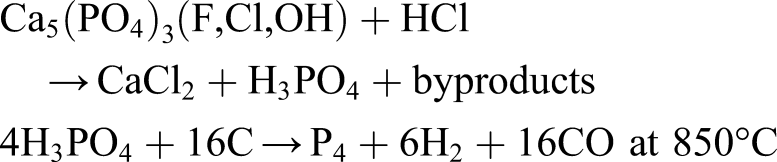
Apatite may be initially rapidly leached with 2.0M HCl with near 100% efficiency (it is more efficient to acid leach in two stages
23
):
Thence, the second reaction can proceed. Unfortunately, apatite is rare on the Moon. It may be possible to use only the Al p-dopant alone or the dopants must be sourced from Earth (usually P and B). The bulk photovoltaic effect does not require pn junctions but has extremely low efficiency – however, tungsten disulphide nanotubes exhibit enhanced bulk photovoltaic effect but this requires nanotube manufacture. 24
The implementation of several layers for solar cell construction requires a 3D printing approach to emplace each layer to build the solar cells. Si inks based on doped semiconductor nanoparticles have been demonstrated as suitable for inkjet fabrication but they have limited functionality. Aluminium back-reflectors, electrodes and interconnects may be deposited by evaporation of aluminium at 2470°C or through screen-printing aluminium paste which is cured at 300°C. The TiO2 layer (recoverable from ilmenite processing) acts as an anti-reflective coating. TiO2 in its crystalline anatase form as thin films is a potential photosensitive semiconductor with or without doping. Nanocrystalline n-type semiconductor TiO2 may also be combined with an ultrathin metal layer to form a Schottky diode solar cell. 25 Polymeric solar cells lend themselves to a variety of film coating and printing techniques including spin coating, spray coating, inkjet printing, gravure printing and screen printing. 26 Inkjet printing, in particular, offers versatility.
It is reckoned in situ amorphous silicon solar cell efficiency will be around 5%. 27 Solar cells undergo long-term degradation due to radiation exposure, especially solar protons (requiring annealing at 750oC) and exhibit diminished performance during the high temperatures of the lunar day (requiring cooling). 28 Assuming standard solar cell performance is normalised at 25°C, the daytime surface temperature on the Moon reaches 127°C yielding a further reduction of 30% of the 5% efficiency (i.e. drop of 1.5%–3.5% efficiency) in performance assuming a temperature coefficient of 0.3%/°C for amorphous silicon. The challenges of purifying and doping Si render in situ fabrication of solar cells impractical. The use of iron pyrite FeS2 for sustainable photovoltaics is a possibility but their efficiencies are low at 1–3%29,30 and troilite/sulphur must be sourced in meteoritic deposits. Kesterite is a copper–zinc–tin sulphide mineral found in quartz-sulphide deposits while its synthetic form is copper zinc tin sulphide/selenide (Cu2ZnSnS(e)4) 31 with photovoltaic efficiencies ∼10% 32 which can be inkjet-printed in thin films from ink formed from Cu, Zn and Sn metal salts dissolved in dimethyl sulphoxide solvent. However, kesterite is not indigenous to the Moon but could potentially be found in association with troilite FeS in asteroidal resources. A direct bandgap silicon allotrope with a crystalline cage-structure Si24 may be formed by compressing sodium and silicon into Na4Si24 crystals and baking off the sodium at 100°C. 33 This may potentially offer higher photovoltaic efficiencies but requires imported Na from Earth. Perovskite has a crystal structure with its general ABX3 structure that acts as an absorber on a layer of Al2O3 where X = halogen, B = metal and A = organic/inorganic. The first perovskite was the mineral calcium titanate (CaTiO3) with a bandgap of 3.46 eV which is potentially manufacturable by sintering CaO and TiO2 derived from lunar resources at 900°C – perovskite crystals may be manufactured into thin films from salt solution or sol–gel methods. 34 Methylammonium lead trihalide (CH3NH3PbX3) is the most widely adopted perovskite offering photovoltaic efficiencies over 20% matching silicon but do not tolerate UV exposure and moisture (so require encapsulation in glass). 35 However, perovskite energy conversion is high only for small-scale cells and do not scale up to uniformity due to ion migration under illumination. Perovskites are currently being adopted to contribute overlying shorter-wavelength absorbing layers to underlying longer-wavelength silicon cells to form multijunction cells but their high lead content is a detractor 36 (though CaTiO3 is a potential option 37 ). Although not an issue for a lunar application, it is uncertain if perovskites can be adopted for lunar photovoltaics due to their marginal conversion efficiencies. Semiconductor nano-crystals demonstrate the migration of excited charge carriers into the valence band when the incident energy exceeds three times the nanocrystal bandgap energy. 38 This provides for greater useful energy output than is achievable with bulk semiconductors. Silicon quantum dots have increased energy gap with shrinking dot dimensions and exhibit conversion efficiencies of 60%. 39 Both of these technologies require sophisticated manufacturing methods.
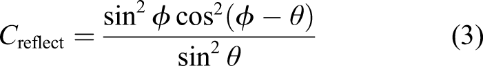
Proposals to ‘print’ solar cells from lunar regolith using a heat source – nominally a Fresnel lens, mirror or laser – mounted on a rover which traverses the lunar surface fusing regolith into solar cells are unrealistic. There are several potential difficulties with this notion: (i) lunar minerals yields lunar glass which will be coloured by iron impurities; (ii) pure silica is rare on the Moon where minerals are in silicate form which is unlikely to yield Si with sufficient purity for solar cells; (iii) although group III acceptor dopant Al may be extracted from the lunar mineral anorthite, the group V donor dopant P will be much more difficult to extract from KREEP minerals requiring supply from Earth; (iv) the photovoltaic conversion efficiency from in situ manufactured solar cells is unlikely to be >5%. Solar arrays are also susceptible to some reliability issues resulting in anomalies and even spacecraft failures despite their technological maturity.40,41 All spacecraft subsystems and component reliability follow a Weibull distribution of the form
Why solar concentrators are suitable
Solar concentrators have been employed to increase the photovoltaic efficiency of solar cells.
43
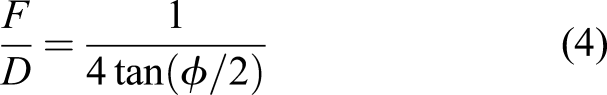
Here, we propose their use for generating thermal energy – indeed, for in situ resource processing, thermal energy constitutes the dominant requirement for pyrochemical, electrochemical, sintering/melting, etc., processes and most 3D printing processes. A solar furnace comprises of a parabolic antenna which intercepts solar flux and focusses it onto an offset feed mirror which concentrates the beam to the target. For any mirror or lens, focal length is the distance at which parallel incident light is converged to the focal point. The fundamental physical limitation on optical performance is f-number, the ratio of focal length F to aperture diameter D, which cannot be less than 0.5. For a parabolic reflector, 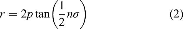
Energy density (W/m2) is given by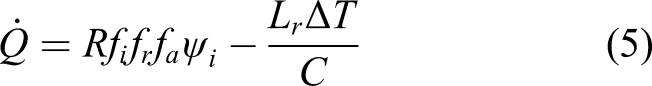
Traditional refractive lenses offer an alternative to reflecting mirrors as solar concentrators, for example, liquid water lenses offer concentration ratios of 100 or more but this is insufficient for lunar power generation applications.
46
However, lenses tend to be bulky. Fresnel lens concentrators are thin lenses that are characterised by engraved concentric prismatic grooves to emulate a conventional spherical lens. Each circular groove acts as a prism at a slightly different angle according to its radius to form a single focus. Pitch between prisms is given by
47
A segmented 25 m diameter filled aperture Fresnel lens has been fabricated on a thin membrane independent of its F-number. 53 Long F-number is tolerant to surface figure errors including cm-scale ripples perpendicular to the membrane as long as the membrane retains its parallelism. This is because light reflecting from a surface bump introduces a path delay of twice the ripple height. However, traditional grinding and polishing is insufficient for rendering required accuracies but 1D micro-etching can be implemented using either chemical or tool etching to remove ripples from ∼10 μm down to ∼100 nm. Fidelity was controlled through thickness measurement through interferometric feedback. The Fresnel lens was fabricated in fused silica segments edged with Ti-alloy film using photolithographic tools that were subsequently precision-assembled using non-nested Origami folds. For the required λ/10 wavefront quality, a minimum of 5–10 μm positioning accuracy in alignment is required. Thermal control is essential to control thermal expansion as the largest source of error and vibration isolation is essential during assembly with planar robotic manipulators on a table marked with fiducials.
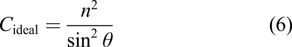
For both parabolic reflectors and Fresnel lenses, the ideal (Winston) concentrator ratio Cideal in the 3D case is given by
54
The geometric concentration ratio is given by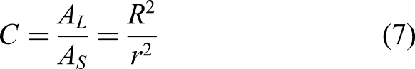

Solar concentrator-based sintering offers a thermal lance technique more suited to lunar application but without the high-power precision of the laser. Fresnel lenses or parabolic mirrors direct heat to their immovable foci but locating fibre optic cabling at the foci allows thermal energy to be directed as desired. Highly concentrated solar energy can be exploited for energising a wide range of metallurgical and chemical processes such as surface hardening of steels, cladding of intermetallics onto steels and sintering of metallic powders.
58
The same can be exploited in the context of a solar power-energised 3D printer, to melt layers of sand, for example, Markus Kayser’s Solar Sinterer.
59
Silica with a melting point of 1600°C is usually sintered in a high temperature furnace but the addition of Ca, Al, Mg and Cl lowers the melting temperature to 500–700°C to permit low power sintering at 200 W.
60
We have conducted Fresnel lens experiments to use concentrated solar heating to melt aluminium alloy onto silicone plastic substrates as a prerequisite to a solar-energised multi-material 3D printer (Figure 1). (a) 1 m2 Fresnel lens; (b) melting aluminium–zinc alloy chips; (c) deposited as molten metal onto a silicon plastic substrate.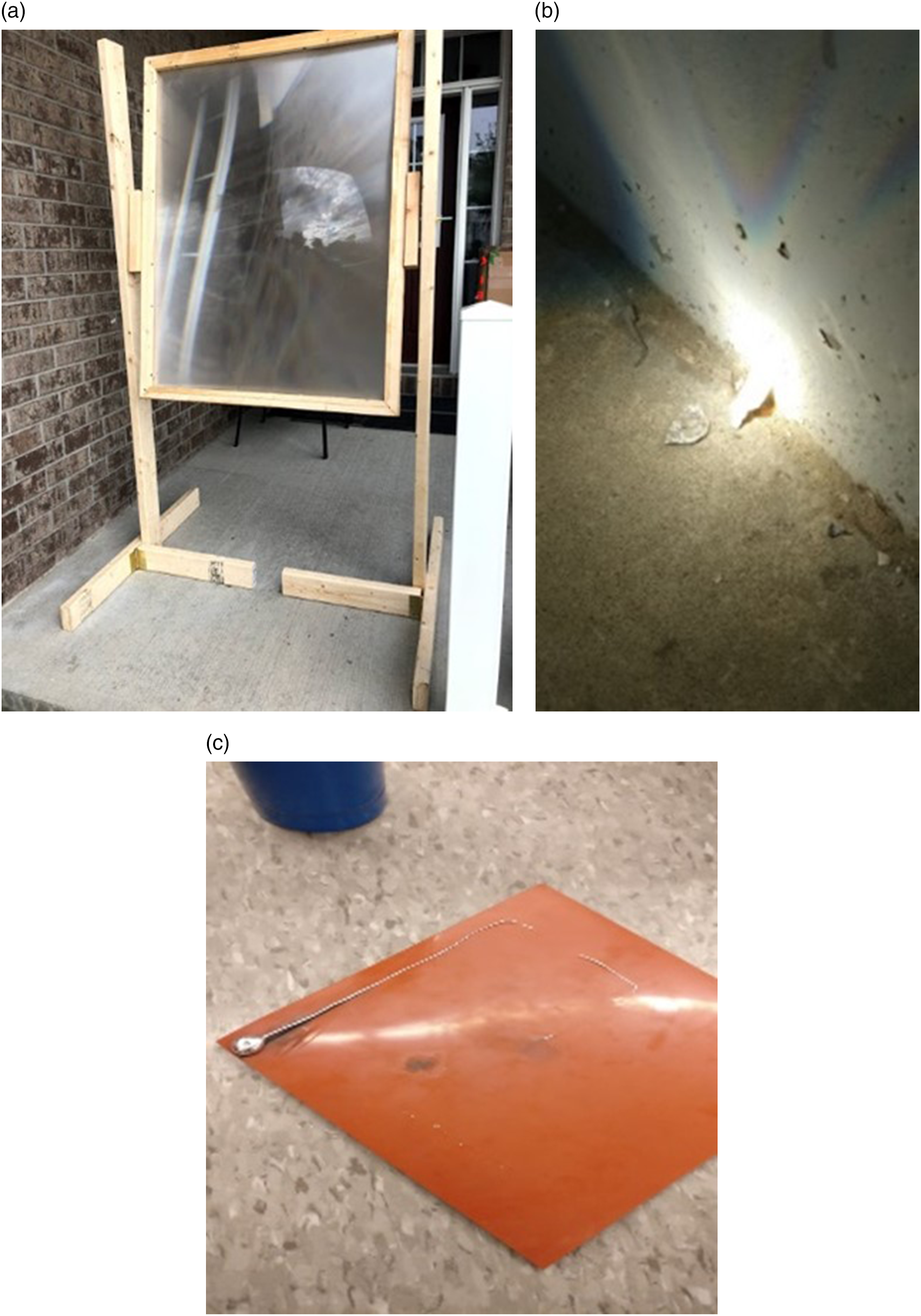
The chief difficulty for bulk material processing is in uniform heating of the volume of material. Optical waveguide transmission lines from an array of solar concentrators can distribute heat through the volume. A parabolic reflector can collect and concentrate solar energy from the primary concentrator focussed onto the secondary concentrator comprising a truncated conical quartz rod coupled to an optical waveguide transmission line (optical fibre bundle) to deliver a high temperature spot to any specific location to implement pyrochemical processing. 61 Multiple solar concentrators may be arrayed to focus energy through multiple fibre bundles into a thermal reactor to generate temperatures exceeding 2000°C. A polymer-clad silica-core step-index multimode low-loss optical fibre was employed for the flexible fibres. 62 The quartz rod similarly coupled to multiple output fibre ends to deliver thermal energy directly into the thermal reactor. 63 The optical chain efficiency was 33% with losses primarily due to losses at the coupling interfaces. This technique can be adapted to sintering/melting within a 3D printer arrangement. A Fresnel lens-based solar concentrator was adopted with fibre-optic coupling to demonstrate the efficient delivery of filtered photosynthetically active radiation of high intensity to a greenhouse as part of a bioregenerative life support facility. 64 In a vacuum, cooling of the focal point may be accomplished by circulating silicone oil around the quartz rod to drive a Rankine cycle engine. Model predictive control is a robust approach to the control of solar-thermal reactors due to its ability to compensate for dead times. 65
The use of polymers for optical devices and optical fibres is well-established. High density arrays of 20–100 μm sized polymer refractive lenses (lensets) used for optical devices can be manufactured through a variety of techniques including inkjet technology based on pulsed piezoceramic microchannel nozzles 66 and spotting arrays of silicon microcantilevers. 67 These approaches render plausibility to the use of silicone plastics for small optical components. Plastic Fresnel lenses are traditionally manufactured through compression moulding and moulds may be 3D printed. However, glass is commonly adopted – on the Moon, carbon is comparatively rare rendering polymers as a less favoured, though not implausible, option. Glass is common to both reflector and refractor-type solar concentrators and fibre optics. Silica is the starting point for the manufacture of ceramics, refractory components, glasses, quartz and silicon. Glass is a mixture of silica with alkaline and alkaline-earth oxide additives. Soda-lime glass with its low melting point of 860oC constitutes 75% SiO2, 15% Na2O and 10% CaO but sodium is rare on the Moon. Similarly, B2O3 for heat resistant borosilicate glass (approximate melting range ∼100°C) is also rare on the Moon. Aluminosilicate glass comprises 57% SiO2, 20% Al2O3, 12% MgO, 5% CaO, 4% B2O3 and 1% Na2O with a melting temperature of 1130°C. Alumina affords strength and durability – sapphire (corundum Al2O3 with traces of other metals) glass is extremely hard. Macor is a machineable glass-ceramic that is a thermal and electrical insulator stable up to 1000°C similar to borosilicate glass with a coefficient of thermal expansion that matches most metals. Most of its constituents 46% SiO2, 17% MgO, 16% Al2O3 and 10% K2O are available on the Moon though its 7% B2O3 and 4% F constituents are not. Lunar regolith may be melted into glass. Anorthositic glass is an aluminosilicate glass with a melting temperature of 1550°C, but it includes significant amounts of FeO which darkens glass – this would have to be removed almost entirely. This increases the complexity of glass manufacture on the Moon considerably. Fused silica glass is pure silica, but it requires a melting temperature of 1710°C, but this is only 160°C higher than that of anorthite. Hence, temperatures of up to 2000 K are required which can be met using Fresnel lens solar concentrators in the 1500–2000 K range. 68 Fresnel lenses of fused silica glass can provide the temperatures required for melting fused silica glass. The effects on different target geometries have been analysed. 69
Approaches to solar-electric conversion
Radioisotope heating units (RHUs) are commonly (though not exclusively) used to supply heat only without conversion to electric power, for example, the Russian Angel RHU delivers 8.5 W of heat. However, we are concerned with the conversion of thermal energy into electrical energy. Thermal-to-electric conversion is commonly adopted in high intensity thermal sources based on nuclear processes. The thermocouple effect involves two different conductors forming a junction. When one junction is maintained at a known reference temperature, a different junction at a different temperature will generate a voltage. Thermocouples may be stacked in series to form a thermopile. Most thermocouples are based on Ni alloys, Pt/Rh alloys, and W/Rh or Pt/Mo alloys, the latter for high temperature furnaces. They create power from heat differentials but these materials are rare on the Moon. Radioisotope thermal generators (RTG) operate through the decay of radioactive isotopes to generate heat which is converted into electrical energy. RTG isotopes to date have been 238Pu offering a specific power of 0.568 Wth/g and half-life of 88 years, but Pu is scarce and difficult to manufacture. Possible replacements include 241Am with a specific power of 0.115 Wth/g and half-life of 433 years for long duration missions, and 90Sr with a specific power of 0.935 Wth/g and half-life of 29 years for shorter missions. 241Am is generated by 241Pu decay in greater volumes than 238Pu. The primary mechanisms for energy conversion to electrical energy in nuclear power sourcess are thermoelectric conversion for low powers (adopted in RTGs) and Stirling cycle dynamic conversion for high power (adopted in nuclear reactors). Longitudinal thermoelectric conversion involves the Seebeck effect due to temperature differences as the transduction mechanism with
Closed cycle turbine energy conversion offers higher efficiency (at the cost of mechanical complexity and fluid handling) than static conversion mechanisms. The Brayton and Rankine cycles are typically adopted in gas turbines and steam turbines, respectively. The Brayton cycle comprises four steps on an isobaric single-phase gaseous working fluid: (i) isentropic compression; (ii) isobaric heating; (iii) isentropic expansion and (iv) isobaric cooling. The Rankine cycle is similar to the Brayton cycle but is applied to a two-phase gas/liquid working fluid: (i) isentropic compression of liquid; (ii) isobaric heating into vapour; (iii) isentropic expansion of vapour and (iv) isobaric condensation to liquid. However, Stirling cycle conversion requires a hot/cold temperature ratio
Nuclear reactors are commonly proposed to support lunar bases, but they are currently not under development nor can they be leveraged from in situ resources within the constraints of near-term technology development. Only three types of nuclear reactor have flown in space, all bar one Russian. 72 Molten sodium offers the ideal working fluid for its high thermal capacity and conductivity, high boiling point and low melting point – it is used in alkali-metal thermal-to-electric converter (AMTEC). NaK alloy is liquid at lower temperatures making it ideal as the working fluid for low power nuclear reactors. An alternative is high pressure liquid water which is used as a coolant in pressurised water reactors (PWR), but this requires sturdy structures unsuitable to the mass constraints of space applications (though this constraint only applies if it to be delivered from Earth). Single phase (non-condensing) He gas coolant is a gaseous alternative to sodium-based and water-based coolant in nuclear reactors, for example, it is employed in a Brayton cycle in the gas cooled Magnox reactor. He is inert so it may be used at high temperature and may also be used in some types of variable conductance heat pipes. As these latter heat transfer processes involve recycling He gases, the low leakages can be readily re-supplied from regolith volatiles, He and H2O. However, these are untested technologies in the space domain. The American SNAP-10A reactor used uranium-zirconium hydride (U-ZrH1.7) fuel with NaK liquid metal coolant. It used SiGe thermoelectric power conversion with an efficiency of <1.5%.
The Russian BUK and TOPAZ reactors were stainless steel structures (limiting operating temperatures to 900 K) using NaK liquid metal cooling loops. Si0.78Ge0.22 thermoelectric conversion is used currently, but lead tellurides and silver-antimony-germanium telluride have also been explored but are limited to 825 K. BUK SiGe thermoelectric conversion has an efficiency of 2–5% while TOPAZ used 5 kW thermionic conversion with an efficiency of 10–15%. Thermoelectric silicides are ideal in the temperature range 330–580°C and may be sourced from in situ resources – FeSi2, CoSi and Mg2Si offer ZTmax of 0.2, 0.2 and 1.2, respectively, where
Solar concentrators may be used in conjunction with vacuum tube-based thermionic conversion to generate electrical energy.
77
Thermionic conversion requires vacuum tube materials – fused silica glass, tungsten, nickel, Kovar and calcium oxide which can be sourced on the Moon – a calcium oxide coated tungsten cathode may be sourced from anorthite minerals and nickel–iron meteorites; a nickel control grid and anode may be sourced from nickel–iron meteorites; Kovar wiring may be sourced from nickel–iron meteorites; and a fused silica glass tube may be sourced from silicate minerals. Vacuum tube-based technology has the advantage of being highly radiation-tolerant unlike solid state devices. Microminiature vacuum tubes are based on semiconductor fabrication methods to implement short micrometre vacuum distances between cathode, control grid and anode increasing the efficiency of electron emission. They offer electron speeds close to c compared with 107 cm/s in silicon. The electron gun operates either through thermionic or field effect emission. Field emission microminiature vacuum tubes have cold cathodes that emit electrons through electric field emission on the application of a strong electric field >5 × 10⁷ V/cm rather than thermal heating. Field emission is generated from a sharply pointed tungsten tip held at high negative potential ∼kV with respect to another tungsten electrode. They are typically cold scandate electrodes comprising porous tungsten impregnated with nanocrystalline scandium oxide for a low work function of 1.45 eV, permitting higher current density without heating. Field emission can be enhanced with thermal heating. Field emission is approximately described by the simplified Fowler–Nordheim equation given by

Work functions of common cathode elements.
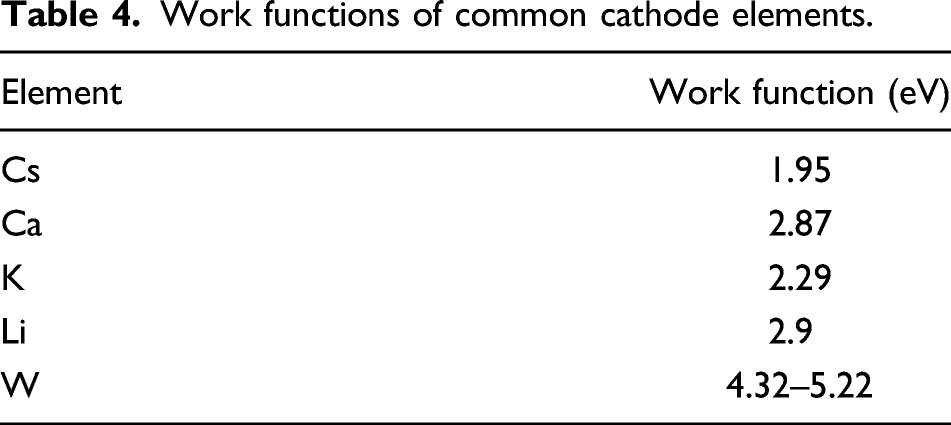
Performance is enhanced with low cathode work function (T∼1500 K) to increase current density but high difference between cathode and anode work functions with the cathode work function being at least 1 eV higher than that for the anode, that is, even smaller anode work function, V = WC−WA∼0.5 eV. Suitable coatings on the cathode are alkaline earth oxides, typically a mix of thorium, barium, strontium and calcium oxides to lower the work function of the cathode to 1.1 eV for 600–800°C electron emission. The most commonly used coatings are cerium oxide, lanthanum oxide and thorium oxide. Impregnating the cathode with coatings of oxides of Ba–Sr–Ca and/or Sc2O3 also yield lower work functions but Ba evaporates requiring replenishment. Another mixture BaO-CaO-Al2O3 in a 4:1:1 ratio is common.
83
The latter – calcium oxide – is the only readily extractable alkaline earth oxide from lunar resources but may be supplemented by alumina for robustness (also extractible from lunar resources) to yield a work function of 2.87 eV. N-type doping reduces space charging and so thermionic efficiency can reach ∼20%. Oxide-coated cathodes are used in small vacuum tubes but not high-power tubes due to sputtering. Thermionic energy conversion exploits electrons as the working fluid in a vacuum which flow from the emitter to the collector through a circuit. However, there is a limit to current density as electrons build up in the cathode–anode gap creating a space charge barrier described by the Child-Langmuir law. The space charge effect of large numbers of electrons mutually repelling each other and the positive cathode attracting electrons back forming an electron charge cloud around the anode decreases thermionic conversion efficiency. The space charge prevents electrons from being emitted from the cathode. There are several ways to minimise this
84
: (i) employ readily ionised caesium vapour (or, to a lesser extent, methane), though K as another low ionisation energy alkali metal may be substituted; (ii) minimise inter-electrode distance ∼10 μm; (iii) employ magnetic/electrostatic fields to control electron movement – the electrostatic approach inserts a control grid between the cathode and anode. A plasma of Cs ions (with low ionisation energy of 3.9 eV) reduces the space charge effect effectively decreasing the cathode work function to ∼1.5 eV. Cs must be continuously supplied limiting the thermionic converter lifetime, for example, it is the Cs reservoir that limits the lifetime of the TOPAZ reactor to 1 year. Closing the cathode–anode gap to ∼5–10 μm prevents electron space charge build up – to prevent rapid cooling of the cathode, thermally insulating SiO2 spacers may be employed. Alternatively, the addition of a third, positively charged ‘gate’ electrode in the 100 μm gap can disperse the electron space charge cloud without the introduction of ions. To prevent gate currents, the gate should be electron-transparent such as alumina membranes. The application of an electric field can lower the work function barrier and enhance thermionic emission – nano-protrusions at the cathode exhibit the same effect. At a low anode temperature of 300 K, back thermionic emission from the anode can be significantly diminished.
85
The conversion efficiency from thermal energy to electrical energy including thermal emission, conduction and radiation losses is given by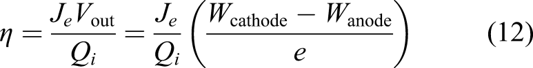
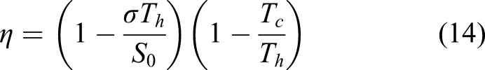
Thermionic emission is limited by the Carnot limit of 44% at Tcathode = 1800 K and Tanode = 1000 K. The 5 kW Russian TOPAZ-II (thermionic experiment with conversion in active zone) space nuclear reactor used thermionic conversion – 15–20% efficient thermionic converters were used with a hot cathode temperature of T C = 1650°C and cold anode temperature of T A = 650°C with a low-pressure Cs environment. 86 Although the theoretical efficiency of this electrical heat engine is 30%, practical efficiencies are limited to 15%. However, the use of electric potential shaping can increase efficiencies up to 40%. 87 In terms of manufacture, vacuum tubes require the implementation of an air bridge or suspended trench filament to create the evacuated space using planar technology. This will present a challenge, though not an insurmountable one, to 3D printing manufacturing processes with lens micromachining with resolution 0.1 μm for surface structuring of Fresnel lenses. 88
Enhancement of thermionic emission with staging has yielded some success. A serial thermionic–thermoelectric conversion stage from 1000°C has demonstrated 30% efficiencies.
89
However, photon-enhanced thermionic emission (PETE) based on combined photovoltaic and thermionic emission from a hot semiconductor offers greater efficiencies of conversion. It is ideally suited to solar concentrators at 1000 sun intensity as a source of both heat and light to pass through a transparent quartz enclosure ∼5–10 mm in size. Photon-enhanced thermionic emission employs two different electrodes in a parallel plate arrangement separated by >1 μm with a p-type semiconductor cathode and a nominally metallic anode (such as nickel).
90
Solar photons with energy above the cathode semiconductor’s bandgap liberate valence electrons of the semiconductor cathode into its conduction band; these conduction band electrons are heated thermionically and accelerated across the vacuum gap to the anode. It is the combination of illumination and thermalisation of electrons that yields the enhanced performance
91
given by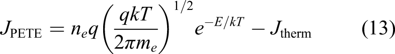
The PETE cell comprises a vacuum sandwiched between a GaAs anode and a heated GaAs cathode from which electron boil-off supplementing photoelectron generation. 92 It can yield up to 30–50% efficiencies and higher if supplemented with secondary thermal conversion processes – this is particularly in the case where high waste heat is removed from the anode into a second thermoelectric (e.g. Mg2Si) conversion stage.93,94 In our application, thermionic conversion is the dominant process limiting conversion efficiencies to 15–20%. In PETE, efficient photonic conversion requires low semiconductor bandgap.
Selenium (which is extractable from asteroid-derived lunar resources) is a semiconductor with a bandgap of 1.95 eV that has been integrated into a multilayer TiO2/Se/MoOx solar cell with Au contacts and exhibits an efficiency of 5.7% (which drops to 3.9% for TiO2/Se/Au) under one sun exposure 95 – it is plausible that molybdenum could be replaced by tungsten. However, selenium is limited by its melting point of 221°C to mild thermal conditions rendering it unsuitable as a cathode material – at best it might be employed as anodic material. Under normal operation, the thermal heating required in PETE is modest compared with that employed in pure thermionic conversion (∼1000°C) but this assumes a relatively low bandgap semiconductor. The cathode should be a p-type semiconductor such as Al-doped Si but Si offers maximum efficiencies of 30% at 580°C with 1000 sun illumination due to its non-optimal bandgap. Undoped silicon (extractable from widespread lunar silicates) as a cathodic material has a relatively low bandgap of 1.1 eV offering higher efficiencies (though suboptimal) of 15% at elevated temperatures >500°C and has a much higher melting point of 1414°C. Aluminium-doped haematite photocathodic coatings 96 (formed from ilmenite-derived iron heated in oxygen) or other photoconductive coatings are also promising. Suitable high temperature metal electrodes include nickel and nickel–titanium–aluminium alloy. Photon-enhanced thermionic emission may be combined with other energy conversion mechanisms at lower temperatures (bottom cycle) at the anode to potentially yield conversion efficiencies up to 70%. This approach promises significant efficiency gains over pure thermionic conversion with efficiencies of 30% being a modest expectation (prior to analysis or experiment).
Approaches to energy storage
We must consider the storage of energy through the two-week lunar night. There exist exotic proposals for thermal energy storage during the lunar night by running a heat engine powered by a heat exchanger pipe from a subsurface region of regolith melted during the lunar day. 97 Additionally, given that temperatures during the lunar night reach as low as 100 K globally and 40 K at the lunar poles, superconducting magnetic energy storage (SMES) might be considered. Superconducting magnetic energy storage requires superconducting wires – niobium–titanium in an aluminium matrix offers a critical magnetic field as high as 15 T but has a critical temperature of 10 K; yttrium–barium–copper oxide offers a superior critical magnetic field of 140 T and a much higher critical temperature of 92 K. The former is impractical but the latter requires only 8 K of active cooling. In the context of ISRU, however, SMES becomes unviable – copper is rarified on the Moon while niobium, yttrium and barium will be difficult to extract from KREEP deposits. However, the most commonly proposed method is chemical battery, for example, Li-ion comprising a lithiated metal (such as Co or Ni) oxide cathode and graphite anode immersed an organic electrolyte with dissolved lithium salts. Li-ion batteries offer a specific energy density of ∼250 Wh/kg and a low rate of self-discharge so trickle charging is not required nor do they need reconditioning. 98 However, they cannot be discharged at a rate exceeding C/2 where C = charge capacity (Ah). Li–S batteries potentially offer much higher energy densities and with reduced flammability. Lithium polymer batteries with their slim profile and high specific power ∼200 Wh/kg are suited to short mission cubesat applications with low power requirements where their low ∼600 charge/discharge cycling is not a hindrance. 99 Li-air batteries use lithium metal which is reversibly converted to lithium peroxide offering potential on Earth – a lunar equivalent could potentially be potassium–oxygen batteries. It has been proposed that lithium’s superior reducing power to hydrogen can be exploited for reducing in situ minerals oxides to metal. 100 On Earth, Li is sourced from chloride brines formed in salt flats dominantly in Bolivia, Chile and Argentina representing finite resources. Unfortunately, Li is not readily available on the Moon. Nickel–cadmium batteries with their lower performance were superseded by Li-based batteries. Rechargeable nickel–iron batteries may be feasible as a power storage mechanism comprising a nickel oxide-hydroxide (Ni(OH)) cathode and an iron anode emplaced in a KOH electrolyte. 101 Fe and Ni may be sourced from NiFe meteorite resources and K can be mined from KREEP minerals such as orthoclase. They were very robust and were used in the V1 flying bomb. A more modern version would replace iron with aluminium extracted from lunar anorthite. However, over the two-week night, these batteries would self-discharge by ∼10–20%.
A fuel cell is an electrochemical machine that converts chemical energy of its fuel (such as water) into electrical energy without combustion. Electrons are released at the anode from hydrogen ions while the oxygen ions migrate through the solid polymer electrolyte to the cathode. Water electrolysis is required for rechargeability in fuel cells which requires polymer electrolyte/proton exchange membrane (PEM), most commonly Nafion. Fuel cells such as alkaline or PEM types have much higher density than batteries due to external H2/O2 fuel storage but this makes them volumetrically bulky. Alkaline fuel cells – which are more robust than PEM-type – use a KOH electrolyte with a saturated separator of asbestos (for which kaolinite might be substituted) and Fe or Ni electrodes. In human missions, they are used in conjunction with a scrubber to prevent carbon poisoning. Lunar bases will produce significant amounts of biowaste – carbon, nitrogen and hydrogen – which may be pyrolysed into syngas (hydrogen and carbon monoxide) which can be converted into methanol. H2 may be combined with CO to form methanol which may be readily stored and then burned for energy. Methanol and oxygen are the fuels required for a sub-category of PEM fuel cells which produce water and carbon dioxide for recycling though their efficiencies are low. NaBH4/H2O2 PEM micro-fuel cell offers high power density ∼700 Wh/kg 102 but they involve fluid control. Appropriate polymers for fuel cell membranes would be difficult (though not insurmountable) to manufacture given the paucity of carbon on the Moon. Furthermore, a separate electrolyser is required to render fuel cells rechargeable. Batteries and fuel cells offer high energy density (capacity to store energy) but low power density (rate of transfer of energy) in spite of some successes. Super-capacitors are a hybrid between a capacitor and a rechargeable battery. They have enormously increased charge storage capacity. Supercapacitors offer high power density with moderate energy density ∼20 Wh/kg with measurable charge state, no memory effects and high charge/discharge cycling capacity. 103 They employ a double layer of thin aluminium foil electrodes covered with activated carbon soaked in KOH/H2O electrolyte separated by a thin porous insulator of woven glass fibres (such as cobalt oxide). Carbon powder electrodes offer very large surface area for the storage of charge. Similarly, K must be mined from KREEP minerals which imposes challenging chemical processing requirements.
Layer-by-layer self-assembly may be applied to the construction of PEM fuel cells and electrical double layer supercapacitors. 104 It is possible to create complex components from inks such as Li-ion micro-batteries ∼1 mm2 using a mixture of lithium and silver nanoparticles in solution. The inks solidify into the battery’s anode and cathode and can be built layer by layer. An enclosure is capped on and the electrolyte added. The construction of batteries through 3D printing has been demonstrated in a zinc-air cell. 105 A customised Cartesian gantry robot configuration of a 3D printer was used to implement freeform deposition using different cartridges. Two plunger-based extruder deposition heads with integral heaters were dedicated to plastic/metal and liquid/pastes, respectively. The material for each printer head was easily changed by substituting different syringe cartridges in each extruder head. The zinc-air battery comprised multiple layers with Zn anode particles in a KOH solution surrounded by a silver paste layer, carbon black/MnO2 cathode catalyst in KOH solution electrolyte, and a pre-cast separator layer of insulating ceramic foam overlying an air (oxygen) cathode surrounded by a silver paste. The assembly was mounted within an ABS plastic casing with copper wiring to the electrodes. In addition, a passive flexure joint of silicone plastic between rigid ABS plastic members was fabricated. The silicone was impregnated with carbon black while embedded wires of silver/methylcellulose paste were also fabricated within the joint – a simple actuator. This illustrates the potential of 3D printing to manufacture energy storage devices though the zinc-air battery, Li-ion battery and PEM for rechargeable fuel cells are unsuited to lunar deployment due to the lack of suitable materials in lunar feedstock.
Why flywheel energy storage is suitable
Flywheels (electromechanical batteries) have been proposed for supplying excess power of peak loads above base loads (typically 55% above peak loads).106,107 They are also proposed as a suitable energy storage mechanism for vehicles.
108
Flywheels for energy storage are robust with zero depth-of-discharge, insensitivity to the number of charge/discharge cycles ∼107 and offer both high energy density ∼100 kJ/kg and high power density ∼50 Wh/kg. A flywheel is a rapidly rotating thin rimmed wheel that stores rotational kinetic energy electromechanically operating as a motor and releases it as a generator. The amount of energy stored is proportional to the square of its rotational speed, typically 20,000–50,000 r/min (a) 3D printed DC motor with wound coils; (b) compact version of 3D printed motor (with wound coils) versus off-the-shelf motor.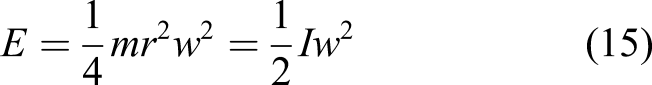
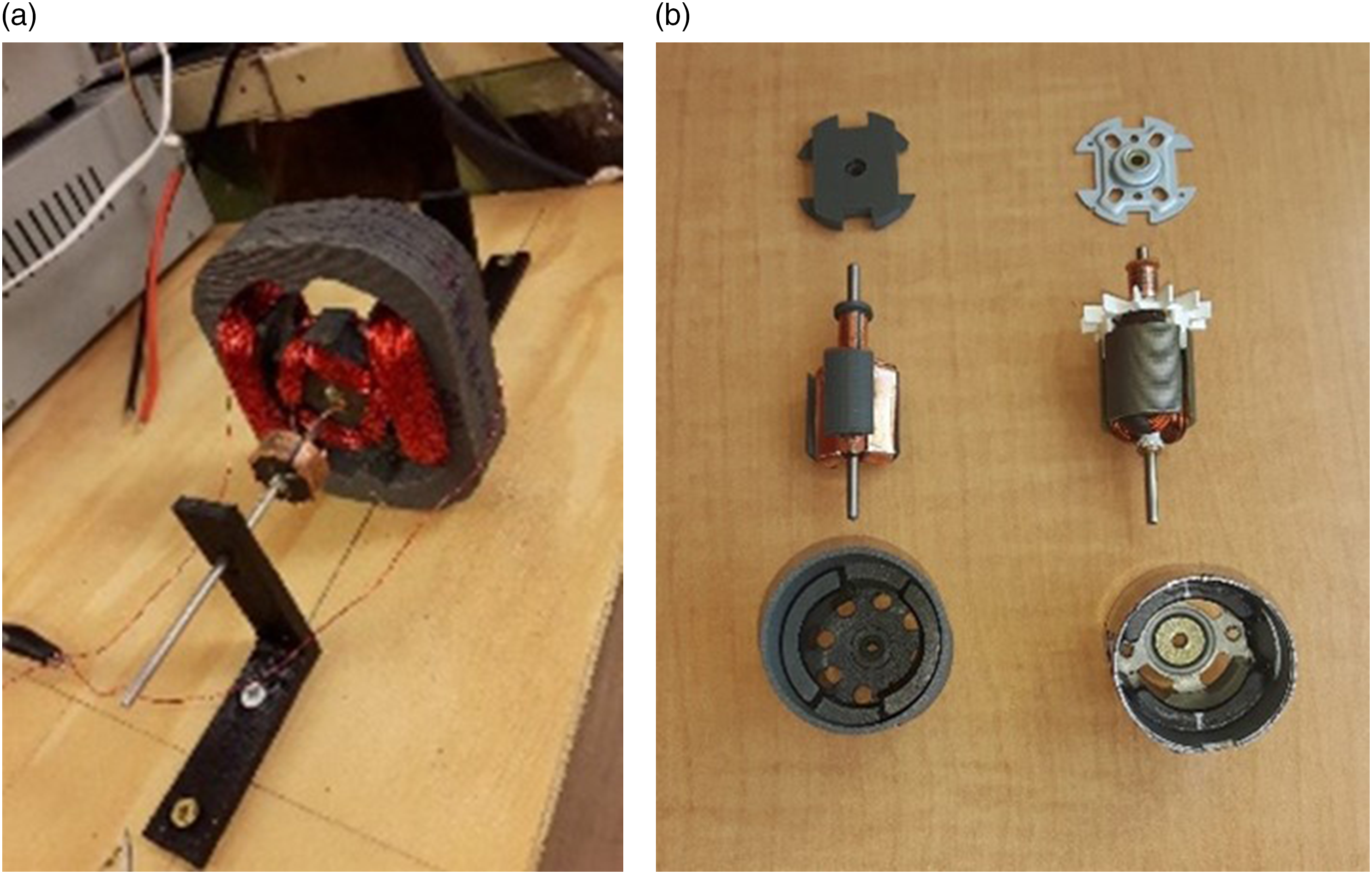
Electromechanical batteries can be constructed from lunar-sourced materials – cobalt-ferrite or alnico magnets from nickel–iron meteorites, aluminium wiring from anorthite, silicon steel/ferrite/silica electromagnets from ilmenite and aluminium/ceramic structure from anorthite and other silicates. The commonest failure mode is separation of the rim from the spokes. To prevent explosive fragmentation, flywheels should be encapsulated in an armoured containment vessel of steel and/or Sorel cement (derivable from lunar resources and Earth-supplied Cl) and buried.
Flywheels are accelerated and driven by electric motors to high speed to store energy and this mechanical energy is drawn to generate electrical energy. The motor output torque is given by 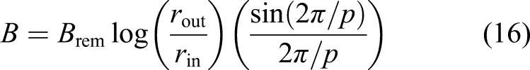


Because this system is ironless, there are no eddy current losses. There are no back-induction effects making the ‘air’ rotor more efficient. The lack of iron core makes the Halbach motor lightweight. The power output is given by
The Halbach motor may be operated as a DC or AC motor depending on its commutation mechanism. A variation on the Halbach motor is the power ring configuration which spins about the vertical axis and exploits shear force levitation. 111 Windage losses due to air resistance are proportional to the cube of the velocity and tend to dominate over copper and iron losses in rapidly spinning rotors but vacuum conditions eliminate this – on the Moon, the vacuum is ambient. The rotor wheel is suspended on magnetic bearings within a vacuum chamber to minimise friction. On the Moon, the magnetic bearings are required to suspend less weight than on Earth. Flywheels are capable of rapid charge and discharge with high efficiency ∼95%. Double-fed induction motors have been proposed as flywheel actuators. 112 Our self-assembling panels were based on double-fed rotor and stator coils. 113
Flywheels are highly suited to energy storage in vehicles. 114 A counter-rotating wheel is typically employed prevent gyroscopic reaction torques during direction changes. For example, in spacecraft, energy storage may be combined with attitude control systems – integrated power and attitude control systems – through two counter-rotating wheels per axis: the rotor speed is typically much higher for power storage than required for attitude control (<10,000 r/min). 115 NASA’s G2 flywheel is constructed from a titanium hub with a carbon fibre rim spinning at 60,000 r/min on magnetic bearings with a storage capacity of 525 Wh and motor power charge/discharge rate of 1 kW. 116 Its motor is a two-pole permanent magnet synchronous motor mounted in the hub with position/angle sensors for feedback. The 100 kg modular assembly is 50 cm diameter by 100 cm axial length. Much higher ratings are feasible with larger flywheels ∼1.5 m length by ∼1 m diameter with ∼ MJ capacities and ∼GW charge/discharge rates. 117
Conclusion
In considering the most appropriate form of energy generation and storage that can leveraged from lunar resources, we propose that solar concentrator/thermionic converters and flywheels, respectively, can be constructed from lunar materials whilst offering high performance. There is little doubt that using local resources to supply power would be boon for lunar colonisation. There are further implications – if we can leverage lunar resources to create energy generation through thermionic vacuum tubes and storage through electric motors, we can also create entire kinematic machines from 3D printed motors, electronics and structural members derived from the same components. Kinematic machines include roving vehicles and mining mechanisms to extract the materials bootstrap our lunar infrastructure. From linear motors, we can create electromagnetic launchers to launch from the lunar surface using renewable electrical energy rather than finite water resources as propellant/oxidiser. From a few critical components – motor and vacuum tube – we can assemble a vast array of capabilities. We have, in effect, a universal constructor machine first envisaged by John von Neumann who had the insight to realise that it was the key to any practical self-replication capability. This is in effect a 3D printer which can print its own parts including its motors and control electronics (which can be employed for other machines). These key components for our energy infrastructure serve as a leitmotif for the construction of other aspects of a basic lunar infrastructure. We believe that this is the only cost-effective means for robust space exploration by exploiting the locally available resources.
Supplemental Material
sj-pdf-1-pig-10.1177_09544100211029433 – Supplemental Material for Generating and storing power on the moon using in situ resources
Supplemental Material, sj-pdf-1-pig-10.1177_09544100211029433 for Generating and storing power on the moon using in situ resources by Alex Ellery in Proceedings of the Institution of Mechanical Engineers, Part G: Journal of Aerospace Engineering
Footnotes
Declaration of conflicting interests
The author(s) declared no potential conflicts of interest with respect to the research, authorship, and/or publication of this article.
Funding
The author(s) received no financial support for the research, authorship, and/or publication of this article.
Supplementray material
Supplemental material for this article is available online.
References
Supplementary Material
Please find the following supplemental material available below.
For Open Access articles published under a Creative Commons License, all supplemental material carries the same license as the article it is associated with.
For non-Open Access articles published, all supplemental material carries a non-exclusive license, and permission requests for re-use of supplemental material or any part of supplemental material shall be sent directly to the copyright owner as specified in the copyright notice associated with the article.