
Abstract
This article introduces an original model-based design methodology addressing a high-performance aircraft design challenge: conflicting performance requirements. The case study of the Global 7500 elevator actuation system also provides in-depth insight into the complex design process of today’s fly-by-wire flight control systems. The methodology presented here redefines the aircraft manufacturer’s involvement in the design process of the systems, implementing analysis and iteration capabilities early in system development. To this end, it introduces a novel modeling approach for analyzing loaded rate requirements by simulating closed-loop performance with a generic nonlinear second-order state filter, including the main performance limitations without requiring a preliminary design definition. In this way, it provides means to mature the system requirements and addresses requirement conflicts upfront. Then, a simulation-based preliminary sizing and performance assessment validates the candidate design concept. It also secures the preliminary design phase by implementing advanced design uncertainties and involving interfacing systems and disciplines early in the process. The redefined methodology identified directly that the problem’s root cause was a conflict between stability and control and flutter protection requirements. It also indicated that the first sizing driver is the response time required under a specific failure case. These findings lead to an optimal elevator actuator design compliant with matured performance requirements. Thus, the methodology resolved a design challenge blocking the Global 7500 aircraft development and prevented redesign occurrences later during the detailed design phase. In this way, it directly contributed to the successful development of the Global 7500 and its optimal operational performance. This methodology applies to future aircraft design challenges, and the technical insight provides valuable lessons learned for high-performance T-tail business jets.
Introduction
The article’s scope is limited to the beginning of the flight control system’s preliminary design or the start of the equipment definition, as per the development process shown in Figure 1. This process is derived from the typical one.1,2 The system’s preliminary design aims to define the equipment and verify compliance with the system’s technical, marketing, and cost requirements. It leads to the equipment’s space envelopes, the component specifications, and the system interface specifications. Flight control system’s design process V-model.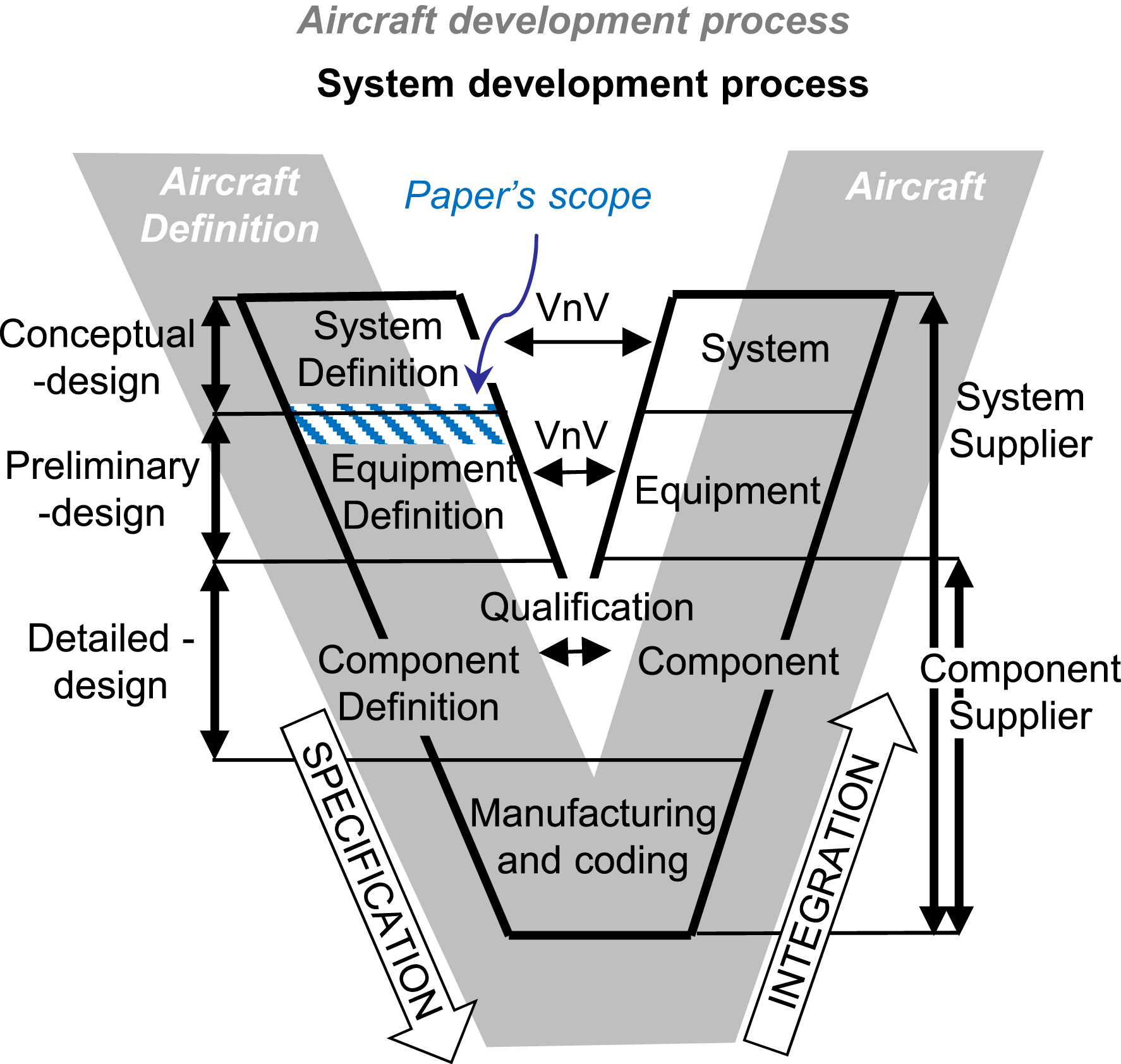
The typical development process, shown in Figure 1, is modified to reflect its evolution with the system supplier’s addition. The aircraft manufacturer owns the aircraft development process, which integrates the system developments. A system supplier owns his or her system’s design and integration, and in theory, the aircraft manufacturer’s involvement in there should be limited to oversight, refining system requirements and integrating at the aircraft level. In reality, as the flight control system is the interface of all the critical aircraft systems and disciplines, its design process is highly complex and requires intensive aircraft-level iterations during the system and equipment definition and integration. This article tackles the conflict between the limited aircraft manufacturer’s involvement and the need for intensive aircraft-level iterations. To this end, the article proposes an alternate methodology that redefines the aircraft manufacturer’s involvement.
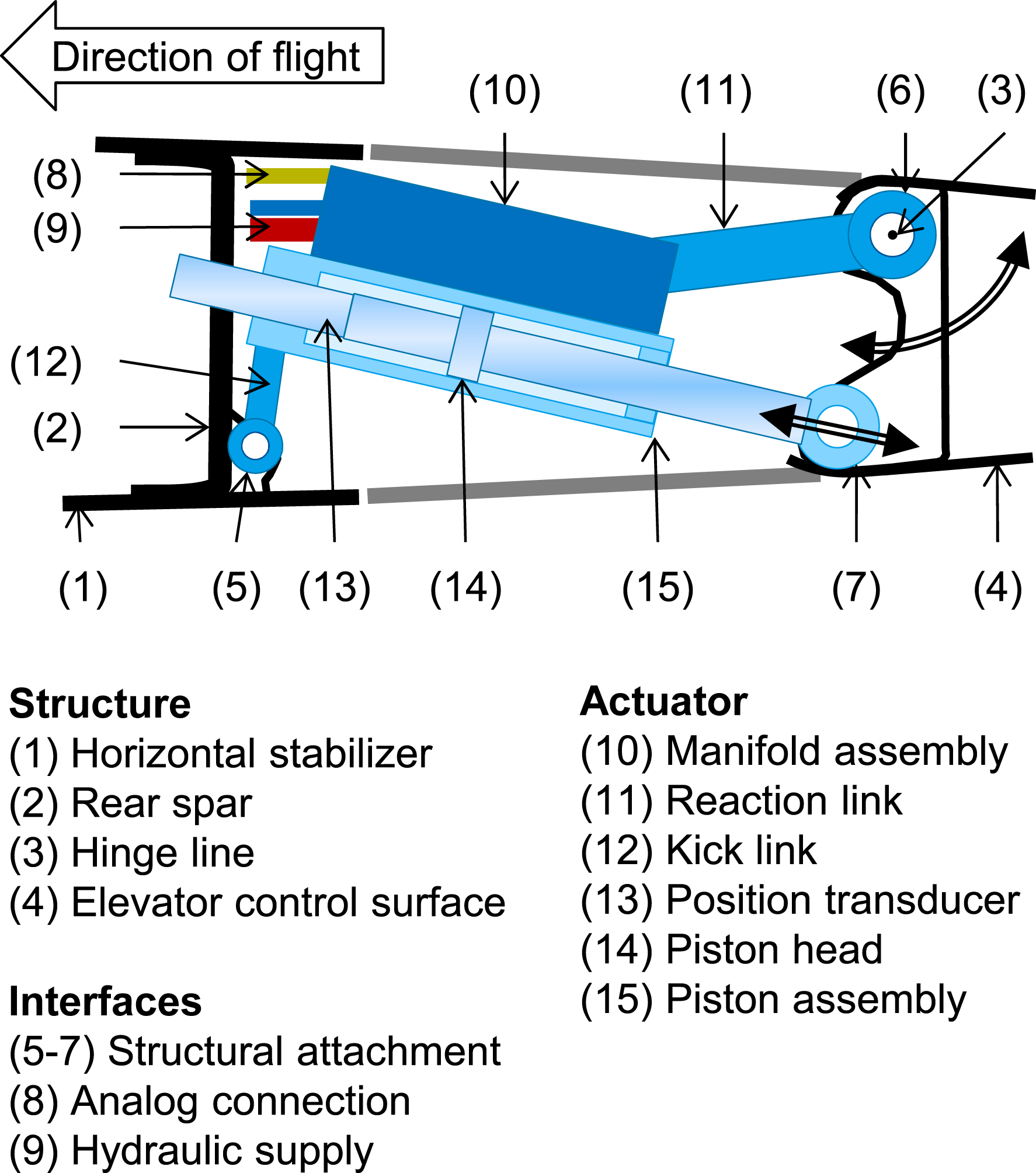
The Global 7500 aircraft is a high-performance business jet produced by Bombardier. It is equipped with an advanced fly-by-wire flight control system inherited from the Bombardier CSeries (also known as the Airbus A220). Figure 2 illustrates the studied elevator actuation system, which is part of the flight control system. The system representation is simplified for confidentiality and clarity; for example, redundant and backup controls are removed. The equipment specific to the studied system is the actuator, which is based on electro-servo-hydraulic technology. Figure 3 shows an example of a fly-by-wire electro-servo-hydraulic actuator with a reaction/kick-link mount. Simplified Global 7500 elevator actuation system. Photograph extracted from Global 7500 aircraft brochure and factsheet.
3
Example of a fly-by-wire electro-servo-hydraulic actuator with a reaction/kick-link mount, side view.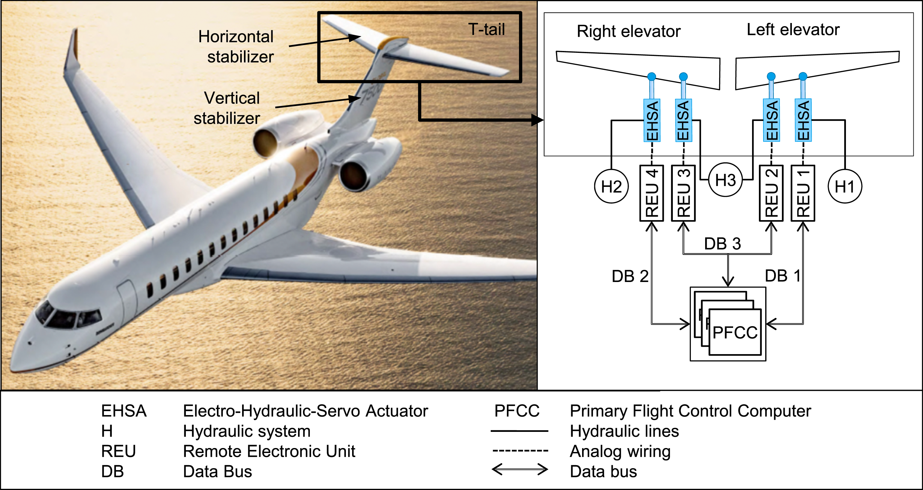
As shown in Figure 1, the aircraft design process parallels the system design process. Thus, as the aircraft definition progresses, the system requirements are refined and updated by more detailed aircraft analyses. Our case study begins with one of these updates. At the beginning of the preliminary design of the Global 7500 flight control system, a revision of elevator actuation performance requirements leads to the elevator actuator being oversized. The oversizing is then propagated to the hydraulic systems, primary structures, and horizontal stabilizer actuator. Such an impact critically increases the cost and delays the development program. In other words, this situation constituted a development roadblock and required a new approach for a rapid resolution.
The new approach had to address the following questions: What are the requirements driving the actuator oversizing? Knowing the sizing drivers, the work can focus on identifying and alleviating overly conservative assumptions and design margins before looking at redesigns. How to assess the dynamic sizing drivers before a preliminary design definition? The performance requirements are conventionally analyzed in a static approximation by the aircraft manufacturer. The lack of a preliminary design definition prevents a dynamic analysis. However, dynamic considerations are critical for high-performance aircraft. What changes are necessary to develop to the actuator, structure, and aerodynamic designs, and what are their impacts? In this article, the focus is on the actuator redesign. How can the redesign be validated and traded with aerodynamics, structures, stability and control, and hydraulic system impacts?
The flight control system development is discussed at the conceptual level, with an increasing focus placed on the more-electric aircraft.4–9 At the preliminary design level, the literature depicts the old-fashioned process without flight control system suppliers1,2,7 and covers the electro-hydraulic servo actuator technology comprehensively.10–12 It also reflects an increasing focus on the more-electric aircraft with the design of electro-hydrostatic and electromechanical actuators.13–17 However, no literature addresses the design challenge of conflicting performance requirements in the preliminary design and the related questions above.
This article discusses how the presented model-based design methodology addresses these questions and thus contributes to the successful certification, entry into service, and optimized design of the Global 7500 aircraft.
The Design Challenge: Actuator Oversizing section introduces the design challenge of the Global 7500 elevator actuation system. In the New Methodology Part 1: Requirements Analysis section, the first step of the presented methodology, that is, performance requirement analysis, is presented. The New Methodology Part 1: Requirements Analysis section also introduces the novel modeling approach for the dynamic analysis of the requirements. It is followed by conceptual design optimization in the New Methodology Part 2: Conceptual Design section and sizing and validation in the New Methodology Part 3: Sizing and Validation section. The overall methodology is summarized and compared to a conventional approach in the Methodology Overview and Discussion section. The final section concludes the article.
Design challenge: Actuator oversizing
This section presents how the conventional preliminary design led to the elevator actuator oversizing problem. The first step is to comprehend the actuation system design and design drivers.
Elevator actuation system
Each elevator control surface is powered by a pair of electro-hydraulic servo actuators acting in parallel. In regular operation, on each elevator surface, two electro-hydraulic servo actuators work together against the operating loads to position the surface as per the command (i.e., position closed-loop control). In case of failure, an actuator transits from active to bypass mode to allow the adjacent actuator, which is not affected by the failure, to keep control of the surface. In case of a double failure affecting both actuators, they both transit to the bypass mode. The bypass mode relies on a fixed orifice between the two piston chambers that provides the damping that protects the aircraft from the flutter phenomenon in flight and from gust impact on the ground. For certification purposes, a single actuator damping is sufficient to protect against flutter.
The design’s drawback appears during the single failure cases: the bypassed actuator drags the remaining active one and increases the elevator’s response time.
System requirements
We focus on two primary system requirements in the studied case: the loaded rates and passive flutter protection because they are the main design drivers.
Loaded rate requirements
The loaded rate requirements ensure that the elevator actuation system can accurately position the control surface with an appropriate response time in all operating conditions. This way, it guarantees that the system provides the required controllability and maneuverability or handling quality to the aircraft. The loaded rates consist of required control surface displacements and response times under different operating loads and system configurations. The operating loads are essentially the aerodynamic forces acting on the control surface and depend on the maneuver, aircraft configuration, and flight conditions. The system configuration describes each actuator’s operating mode (active or failed).
The loaded rate requirements cover both the normal operation cases (i.e., no failure) and failure cases. The failure case performance requirements are alleviated according to the failure severity and probability. 18
Figure 4 illustrates the loaded rate requirements. The control surface displacement is regarded as a function of time. It should achieve the position (3), that is, 95% of the travel between the start (1), and commanded (2) positions, within the response time requirement (4). The positioning should stabilize within the required positional accuracy band (5). Profile (6) illustrates typical compliant performance. Example of loaded rate requirement and compliant performance (6).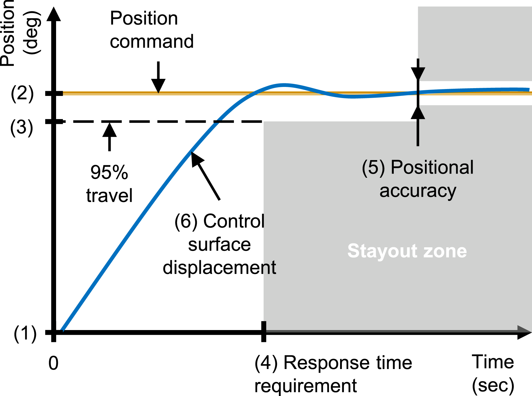
Passive flutter protection requirement
Flutter plays a crucial role in the flight control system design.12,19,20 It consists of a self-excited structural deformation resulting from the interaction between inertial, elastic, and aerodynamic forces. It can be destructive and must be prevented. The passive flutter protection requirement, also referred to as the flutter damping requirement, ensures that the flutter mechanisms are stabilized and guarantees the associated elevator dynamic responses in the loss of the control surface’s actuation.
According to the regulations, 21 here, the critical design case for flutter damping is an asymmetric single actuator disconnect with the adjacent actuator’s failure in bypass mode and “end-of-life” condition. In other words, each elevator actuator shall provide alone the required minimum damping.
Here, the flutter minimum damping requirement is a rotational damping coefficient (N·m·sec/rad) as a function of the frequency (Hz) for a given amplitude of oscillation (deg). Figure 5 illustrates this requirement with a stay-out-zone defined by the minimum damping coefficient (1) and break frequency (2). Profile (3) illustrates compliant performance. Example of minimum flutter damping requirement and passing performance (3).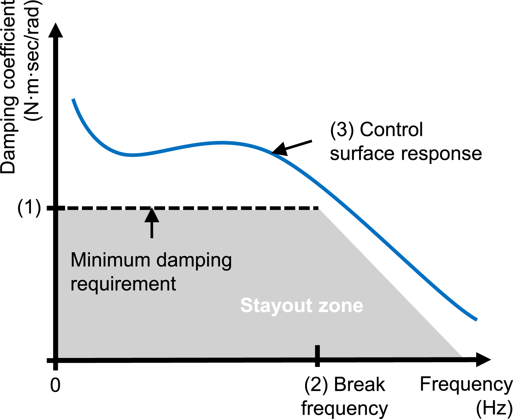
Conventional approach
The first step for the design of an actuator is to define its kinematics. The kinematics depends on the actuator dimensions and mounting, for example, flange, pin-to-pin, or reaction/kick-link mount.10,22 The mounting depends on the installation environment characteristics, for example, space envelope, structural attachment points, and accessibility for maintenance. It is a highly iterative step because the kinematics and actuator dimensions are interdependent. Once the kinematics are defined, the primary actuator components (piston, servo valve, manifold, and control valves) are selected and sized to meet the performance requirements.
In the case study, because of a revision of elevator performance requirements (i.e., system specifications) at the beginning of the system’s preliminary design, the initial actuator was reassessed. Conventionally, this assessment was based on static and dynamic analysis.
Static analysis
The conventional static analysis is driven by the stall load requirement, which is the maximum force applied directly onto the main ram. 1 The stall load is a fundamental design parameter for the actuator ram and determines the actuator’s size within the limitations set by the available standard hydraulic seal sizes. 23
As shown in Figure 6, the conventional static analysis compares the actuation system’s capability (stall load) with the loaded rate requirements in a static approximation (i.e., end deflections and loads). The surface hinge moments are normalized for confidentiality. The actuator stall load capability must cover all the requirements with a given design margin (typically an empirical value). Conventional static analysis of the actuation system capability vs. loaded rate requirements.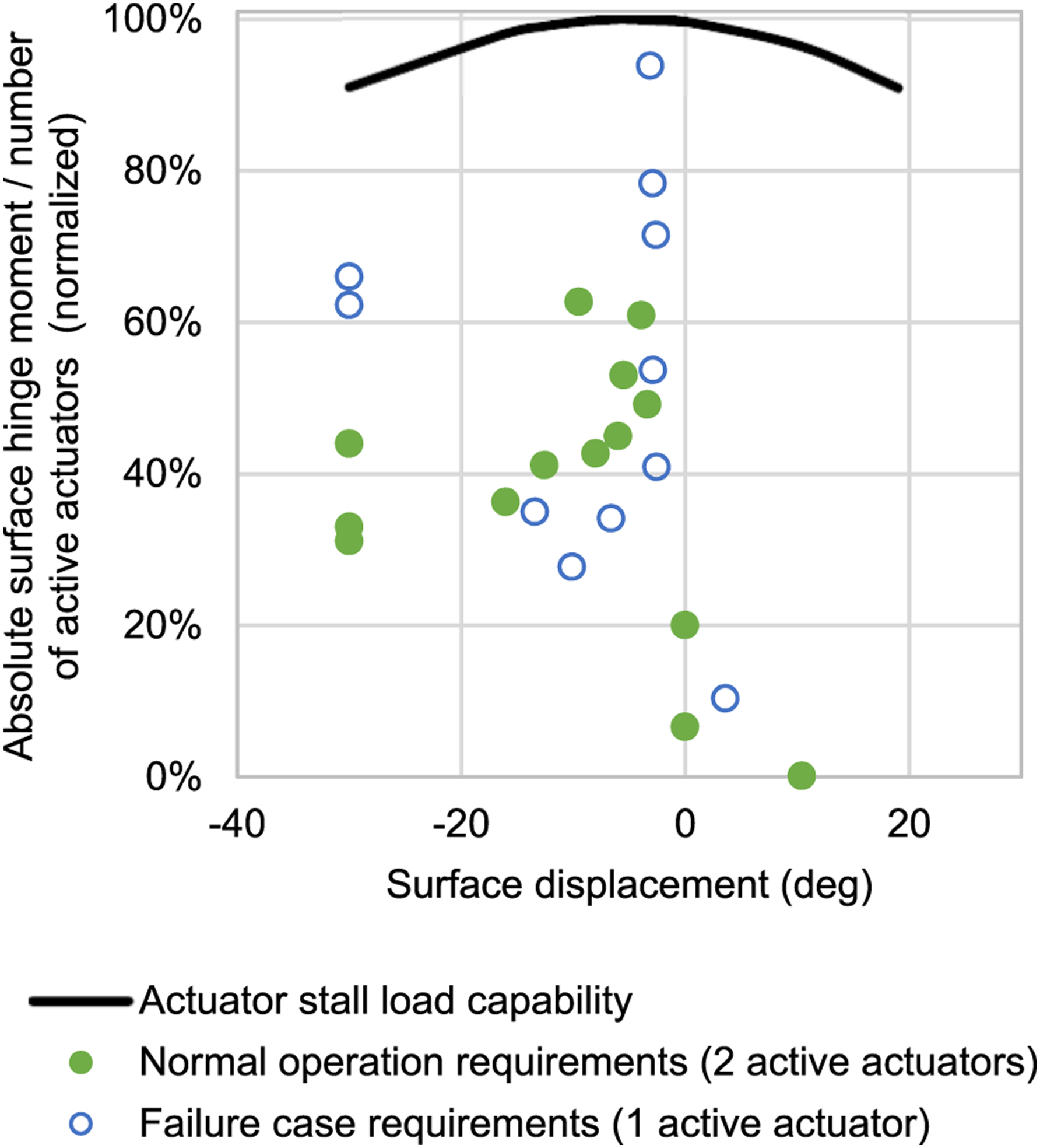
The aircraft manufacturer can use the static analysis to check a requirement update before passing it to the system supplier. The static analysis can also show potential sizing drivers, for example, outlying requirements, to investigate for optimization opportunities. Figure 6 shows that the requirement update mentioned in the previous section does not exceed the actuation system’s initial operating envelope. Thus, no significant design impact is expected; the update passes the check and is submitted to the system supplier.
Dynamic analysis
The system supplier carries out the conventional dynamic analysis of the loaded rate requirements, determining the needed fluid flow and servo valve size. Here, an open-loop simulation evaluates the actuator’s response with a fully open servo valve against the response time requirements. The advantage of such an analysis is that it can be done conveniently with a spreadsheet. It considers all the critical design phenomena driving the actuator performance (hydraulic power supply, servo valve characteristics, fluidic losses, mechanical friction, and external load) except the fluid compressibility and the controller roll-off occurring when converging to the commanded position. Typically, an empirical margin is added to the response time to address the inaccuracy that results from missing the controller.
The dynamic analysis revealed that a design based purely on static analysis would not comply with the response time requirements, especially when failure cases are combined with fast response and high aerodynamic loading. Remarkably, the conventional approach’s first drawback is that the aircraft manufacturer’s static analysis misses this issue.
Oversizing
The most straightforward response to the failure of the initial design to meet the loaded rate requirements is to increase the piston head size. This increases the stall load capability and the velocity under load for a given pressure difference in the piston chambers. This approach typically minimizes the redesign effort and development risk for the actuator.
However, increasing the elevator actuation’s stall load capability implies strengthening the structural environment accordingly (cf. Figure 3). Additionally, a higher elevator actuation capability induces a higher peak load on the horizontal stabilizer and the horizontal stabilizer actuator. In the T-tail configuration (cf. Figure 2), this impact propagates further to the vertical stabilizer carrying the horizontal stabilizer. Thus, increasing the piston head size causes a major redesign and weight impact.
Another consequence is the increased hydraulic flow rate. A higher flow rate induces more hydraulic losses in the valves, fittings, and pipes of the hydraulic systems and the actuator manifolds. In other words, it leads to an increase in power losses. Therefore, increasing the piston size without increasing the hydraulic power supply can reduce the actuator’s net power output and increase its response time. That is why this approach does not allow passing the short response time and high loading cases.
The supplier converged to an out-of-chart figure for this type of application when increasing the piston head size and the hydraulic power supply accordingly. It also critically impacted the hydraulic system and multiple primary structures and thus the overall development program. Therefore, the resolution requires a new approach.
New methodology part 1: Requirements analysis
The first part of the developed methodology analyzes the loaded rate requirements to identify the sizing drivers and thus mature them before engaging the system supplier in the preliminary design.
Requirement model
The sizing drivers can be either static or dynamic. However, the aircraft manufacturer conventionally analyzes the loaded rate requirements in a static approximation only, as described in the Conventional Approach section. The dynamic analysis requires a preliminary design definition of the actuator for modeling its primary physical characteristics driving the performance. Indeed, a conventional physical modeling approach 24 cannot be applied without design parameters such as actuator kinematics, piston sizing, servo valve characteristics, and hydraulic power supply. The objective here is to allow the aircraft manufacturer to analyze the requirements in a dynamic approximation and capture all the sizing drivers. To this end, a novel modeling approach bridging the performance requirements and the actuation dynamics without a preliminary design definition is proposed.
The proposed modeling approach is based on a fully parameterized nonlinear second-order state filter. Such a model has been successfully applied in past works for the inverse simulation of electromechanical actuators.14,16,17,25 It is modified here for simulating a position closed-loop control actuation at the requirement level, that is, without design parameters but representative of the main performance limitations.
The nonlinear second-order state filter is obtained by restructuring a linear time-invariant second-order filter into the generic form, shown in Figure 7, isolating the state variables (position, velocity, and acceleration). Generic second-order state filter model isolating state variables.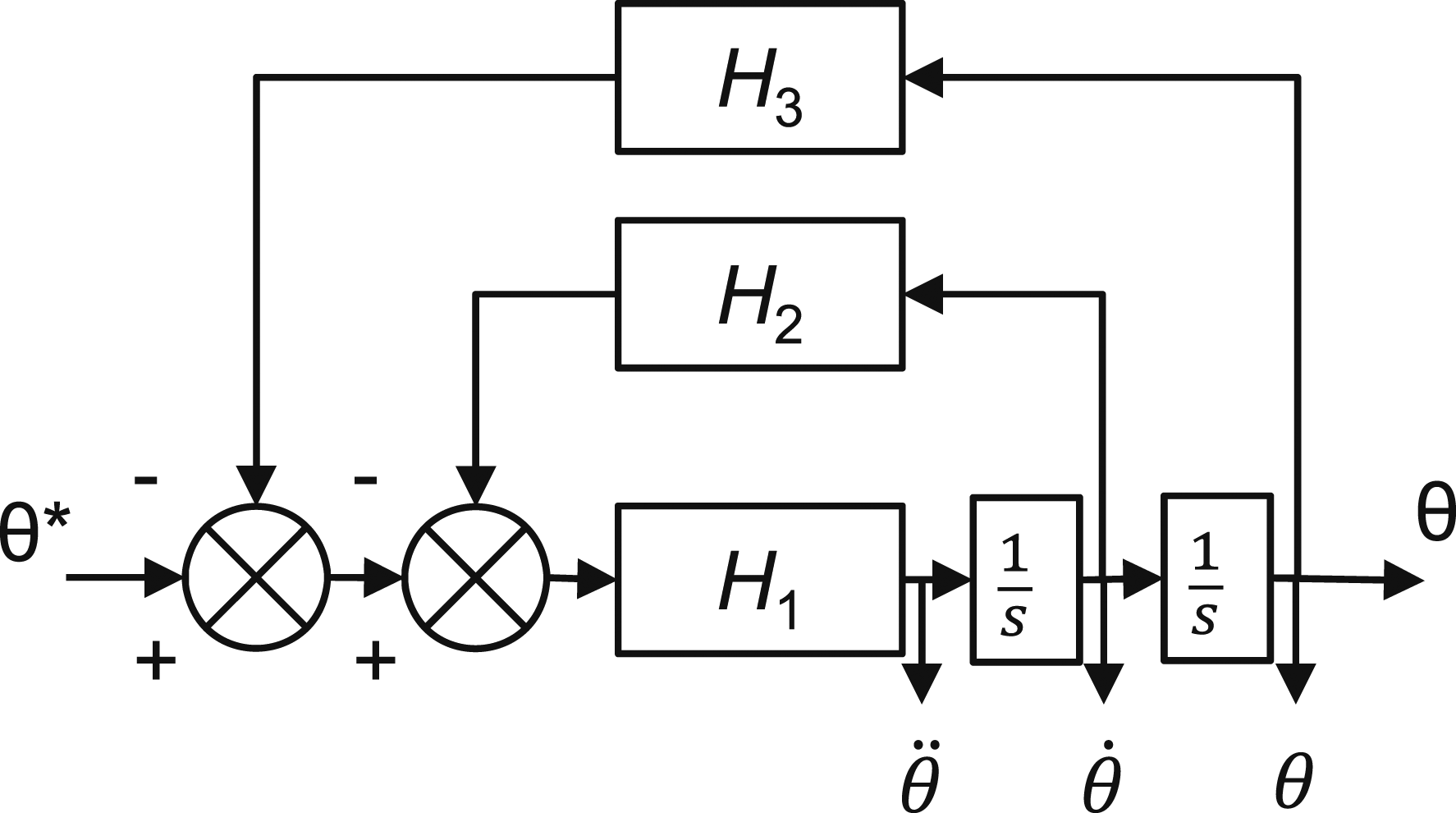
The linear time-invariant second-order state filter is expressed as a transfer function in the Laplace domain as follows
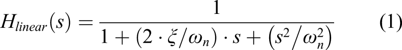
In the same way, the generic filter in Figure 7 can be expressed as the following transfer function
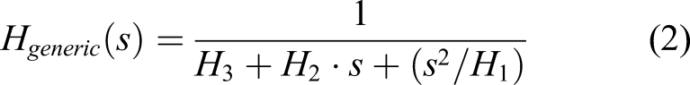
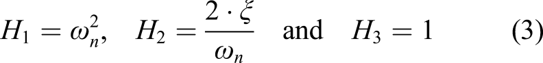
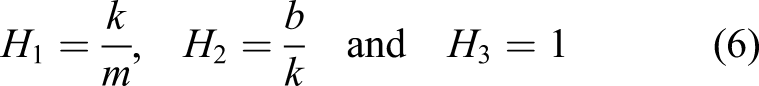
Matching equations (1) and (2) provides the parametrization of the generic filter in Figure 7 modeling a position closed-loop control actuation
Isolating the state variables allows the implementation of a rate limiter, 25 reproducing the control laws’ function protecting the system from excessive commands, physical wear, and fatigue and providing consistent rate limiting behavior. 26
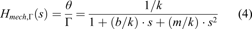
The next step aims to incorporate the nonlinear aerodynamic loading and the nonlinear damping resulting from the servo-hydraulic technology and the flutter damping requirement. To this end, the previous model is modified to simulate the loaded rate requirements with a classic mass–spring–damper mechanical model. The input is a torque Г (Nm) in the rotational domain, representing here the actuation capability. The mass or moment of inertia J (kgm2) represents the control surface. The spring or stiffness k (N·m/rad) represents the aerodynamic loading. The viscous damper b (N·m·sec/rad) represents the flutter damping occurring in a passive actuator in case of failure. The transfer function of this mechanical system is
Assuming that the control surface position converges to the commanded position
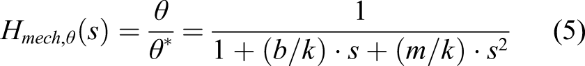
Matching equation (2) and equation (5) provides the following generic filter parameterization for the mechanical system
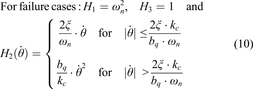
The above mechanical system model needs to be modified to account for the damping and stiffness (aerodynamic loading) nonlinearities. The aerodynamic loading is typically expressed as follows

In the case of a conventional fixed orifice damping design, the damping function is

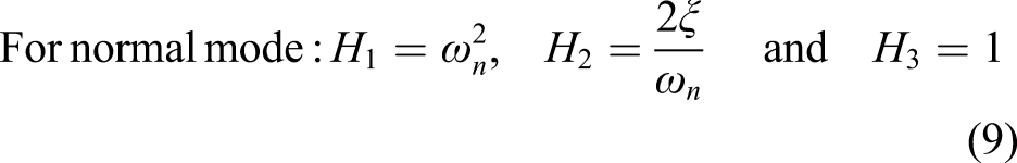
Combining the position closed-loop control with the mechanical system models provides the following generic filter parameterization
The model is completed by expressing the commanded position (i.e., filter input) as a function of a single actuator capability, also referred to as the stall load Г
req
(Nm)
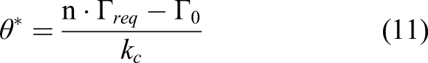
The resulting requirement model reproduces the loaded rate performance of a closed-loop actuation system in both the normal mode and failure case, including the main nonlinearities limiting the performance and without requiring the preliminary design of an actuator, its kinematics, and controller.
Requirement model validation
The requirement model is validated by comparing it to the proven predesign model described in the Physical Modeling and Simulation With Uncertainty section. For the sake of comparison, the requirement model is parameterized to match the actual design output torque capability. In this way, the effect of kinematics, friction, and hydraulic static losses are compensated. The requirement model is also parameterized to match the actual design damping for failure cases. The hydraulic power supply limitation is neutralized, and the command delay is set to zero in the predesign model.
Figure 8 shows the simulated control surface displacements of both the requirement and the predesign model using failure case 21, the design driver discussed in the next section. The profiles (1) in black are the responses for the saturating damping introduced in the New Methodology Part 2: Conceptual Design section. The profiles (2) in red are the responses for a conventional fixed orifice damping. These profiles illustrate that the requirement model reproduces the variation in performance between different designs. However, its dynamics accuracy is limited. Requirement model validation.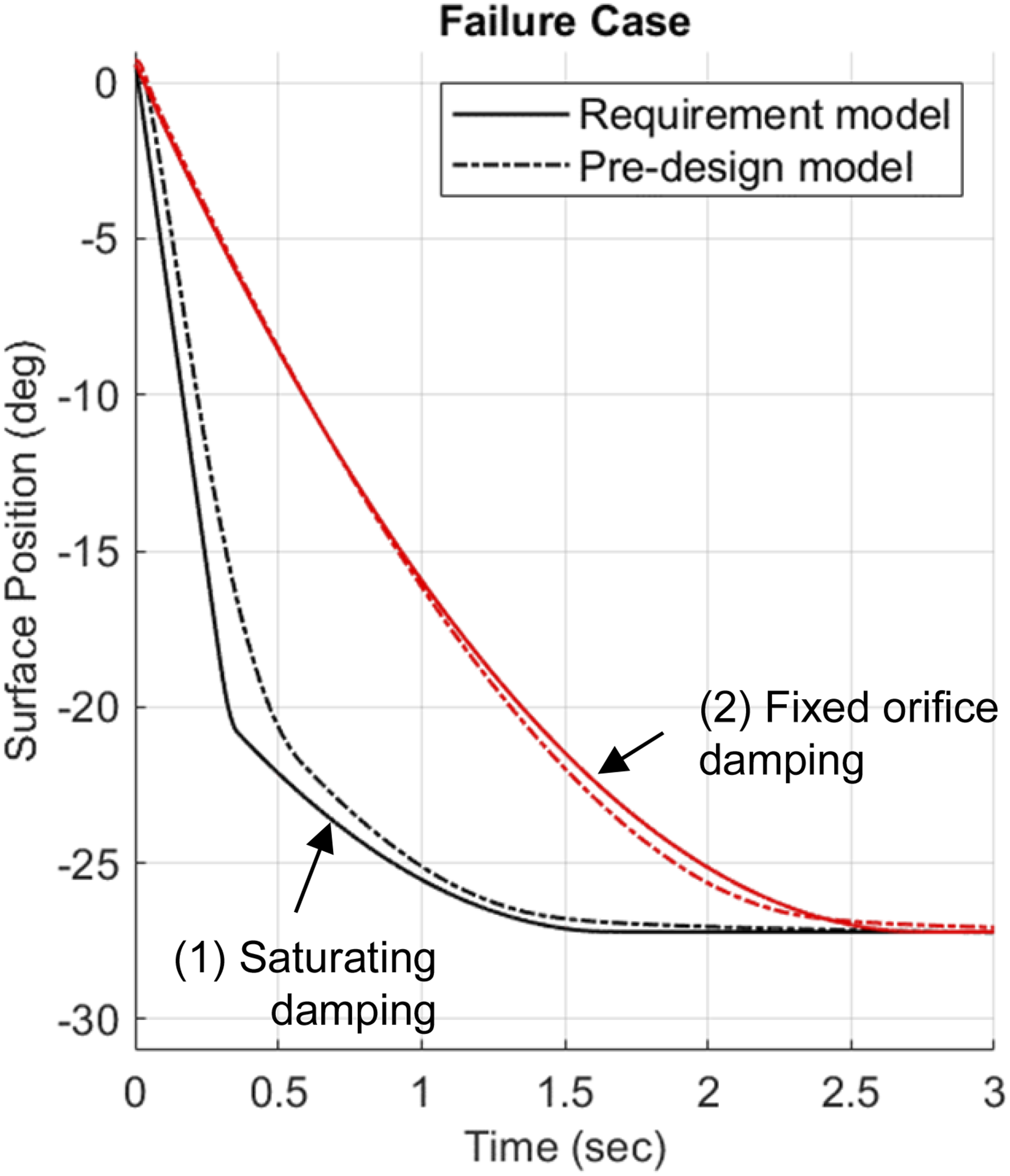
The accuracy of the requirement model and its ability to reproduce the design variation are sufficient for analyzing the loaded rate requirements and investigating design concepts. However, the absence of primary performance contributors such as the hydraulic power supply limitations, the kinematics, and the various losses makes it too inaccurate for preliminary design activities.
Requirement analysis
The requirement model is automatically parameterized for each loaded rate, and the input or actuator stall load is adjusted until passing the response time requirement. In this way, a stall load requirement is obtained for each loaded rate requirement. The most demanding requirement can be easily identified on a plot, as shown in Figure 9. Additionally, the plot distinctively shows the end-position aerodynamic hinge moment (i.e., the static requirement) and the additional hinge moment (i.e., the dynamic requirement), giving more insight into the sizing drivers. Stall load requirements from the dynamic requirement analysis: (a) initial design concept and (b) revised design concept.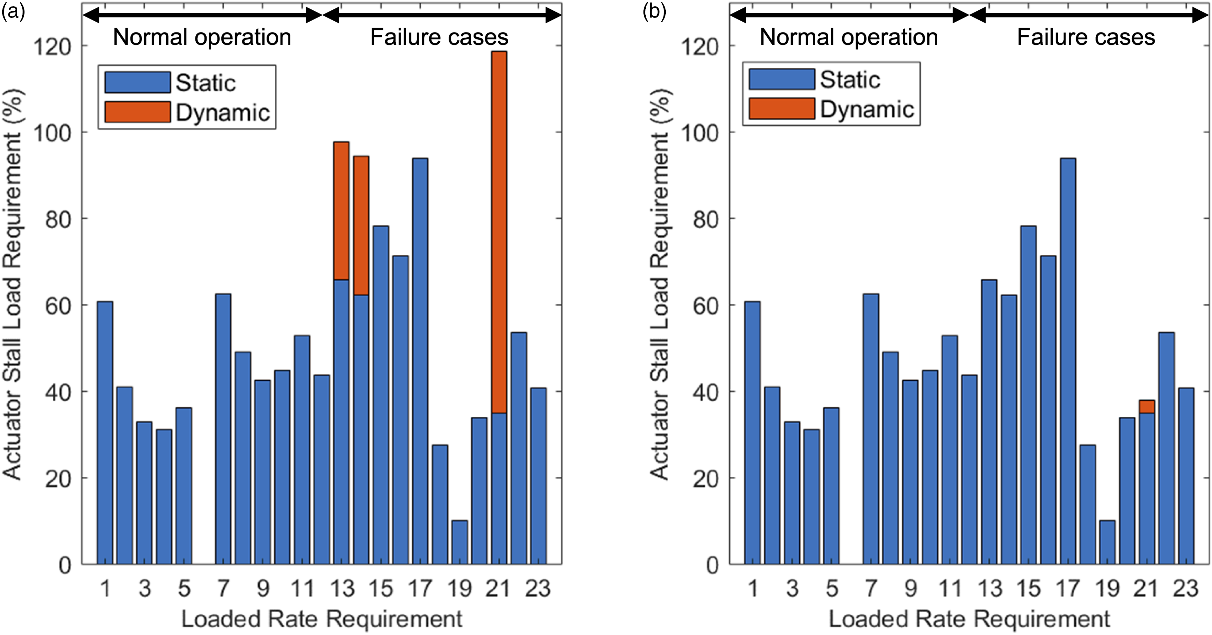
Figure 9(a) shows that the sizing driver is requirement 21 and is mainly dynamic. Requirement 21 is a failure case, meaning that one actuator is active and the other dragging. A sensitivity analysis shows that the dragging is a critical contributor to the dynamic requirement. Therefore, the focus becomes refining sizing requirement 21 and the damping requirement hypotheses. The Stability-and-Control and the Aeroservoelasticity teams are responsible for refining requirement 21 and the damping requirement, respectively. This part of the work is beyond the scope of this report, which focuses on the actuation system design. The outcome is an alleviation of the sizing requirement aerodynamic loading and response time requirements. However, this alleviation is not sufficient to converge to a practical actuator design, and the next step is to define alternate actuator concepts.
New methodology part 2: Conceptual design
According to the findings of the requirement analysis, the search for alternate actuator designs focuses on reducing the effect of the damping requirement during a failure case.
The damping coefficient with the control surface oscillation rate at the break frequency of the damping requirement (cf. the System Requirements section) provides the maximum required damping torque. The revised design concept takes advantage of this maximum damping torque by merging the traditional fixed orifice with a pressure relief valve to limit the damping during a failure case. In this way, when the orifice’s pressure differential reaches the maximum damping torque, the pressure relief valve starts opening and saturating it, as illustrated in Figure 10. Fixed vs. saturating orifice damping.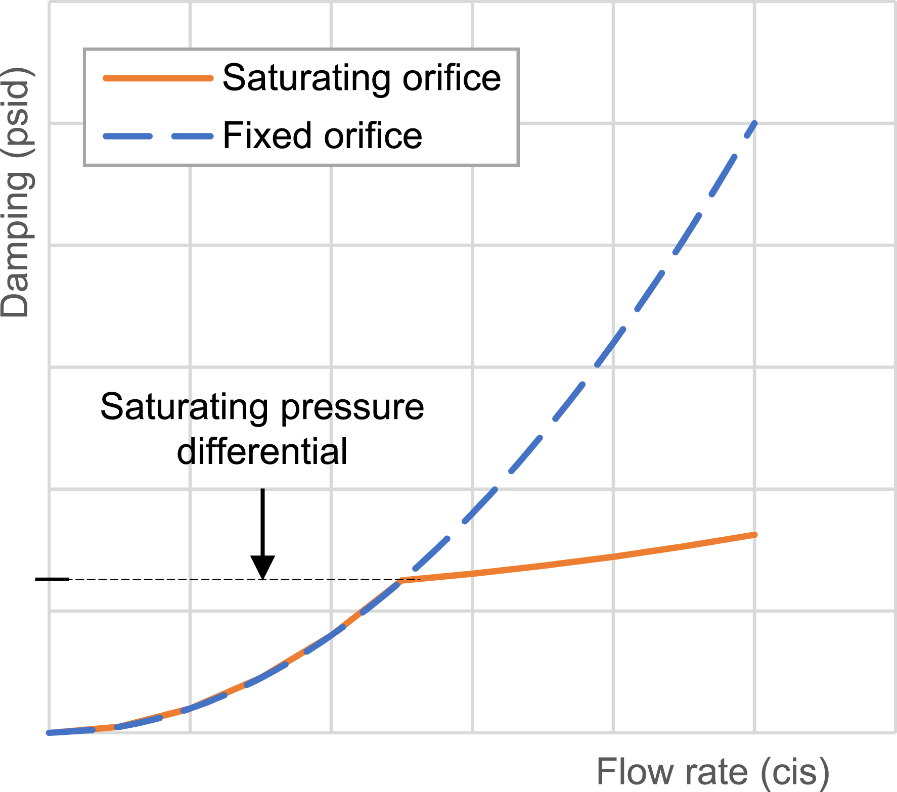
The calculation relies on a rigid fluid approximation. In reality, the fluid compressibility affects the actuator impedance significantly. At low frequencies, the damping orifice flow follows Bernoulli’s equation and provides almost pure damping. At higher frequencies, the orifice starts saturating, and the fluid compresses, thus reducing the damping component of the impedance and increasing that of the stiffness. At even higher frequencies, the inertia contributes to increasing the impedance. Therefore, an empirical margin is added to cover tentatively for these effects.
The requirement dynamic analysis shows that this alternate design can significantly reduce the stall load requirements, as shown in Figure 9(b), and resolve the design problem. The next step is to validate this promising concept.
New methodology part 3: Sizing and validation
The third part of the presented methodology validates the revised design concept described in the New Methodology Part 2: Conceptual Design section, combining robust and simulation-based design approaches to mitigate the development risk. The conceptual design is embodied by defining and sizing its primary components. A performance assessment then verifies compliance with the requirements as the basis of the validation.
Sizing
The sizing’s objective is to minimize actuator weight, interfacing loads, and fluid flow consumption. The constraint is that all the performance requirements must be passed. For robustness, the design must also achieve the loaded rate and damping requirements regardless of the uncertainties.
Before the sizing, the designer defines the primary actuation system components and independent design parameters. These components and parameters are selected for their significant impact on the actuator loaded rate and damping performance. The primary components are the actuator’s structural attachments, piston, servo valve, manifold, damping, kinematics, control surface, aerodynamic loading, hydraulic power supply system, and the controller.
As discussed in the Conventional Approach section, the kinematics is essentially constrained by the installation envelope. For this redesign, a reaction/kick-link mount10,22 is implemented to increase the lever arm and preserve the composite primary structure (rear spar) from excessive loading. The piston head dimensions are adjusted following the industry standards. 23 The servo valve rated flow is adjusted to meet the loaded rate requirements. The damping mechanism is defined to match the conceptual design described in the New Methodology Part 2: Conceptual Design section. The manifold piping hydraulic diameter contributes to the power losses 27 and is adjusted iteratively to pass the loaded rate requirements while minimizing the manifold volume and weight.
As for the design parameters, the uncertainties are selected for their significant impact on performance. The fluid properties affect the power losses and damping and are obtained from internal standards (Bombardier’s specification BAMS 564-003), industry standards,28,29 fluid manufacturer technical data,30–33 and designer experience. They vary significantly with temperature, fluid type, the quantity of contained air, and the possibility of having mixed fluids. Therefore, designer experience is critical for these parameters. Actuator friction affects the stall load capability of the actuator and is driven by the piston seal friction and depends on its design. Due to wear, friction reduces over time. The friction value and variation are typically empirical and defined by designer experience. The piston head and servo valve’s manufacturing dimension tolerances are based on aerospace industry standards.23,34 The manufacturing tolerance of the orifice (discharge coefficient) is based on designer experience. Reducing the manufacturing tolerances, that is, the tolerance design approach,35–37 is avoided for cost containment. The manifold piping length, valves, bends, and restrictions contribute to the power losses.27,38 However, they are defined later during the detailed design, and the designer experience is required to anticipate the magnitude of their effect.
Physical modeling and simulation with uncertainty
The presented methodology relies on physical modeling and simulation for the performance assessment. A lumped parameter model reproduces the interactions between the actuation system’s primary components and interfaces. 24 Each component model is fully parameterized with design or requirement parameters. In this way, it bridges the performance assessment with the design activity, facilitating the sizing iterations, the investigation of alternate designs, and the evaluation of the impact of requirement changes.
Figure 11 shows the model implementation in the MATLAB-Simulink environment. Microsoft Excel spreadsheets serve as a user interface for the parameterization. The architecture of the model reflects the physical design of the actuation system: (1) two actuators, (2) their controller units, (3) two hydraulic systems, (4) kinematics and control surface, (5) the aerodynamic forces acting on it, and (6) the structural environment of the actuator installation. The input (7) is the control surface position command from the flight control system, and the output (8) is the control surface displacement. A MATLAB algorithm manages the model versions, the parameterization, the simulation, the data acquisition, and plotting via a user interface. Elevator actuation system predesign model in MATLAB Simulink.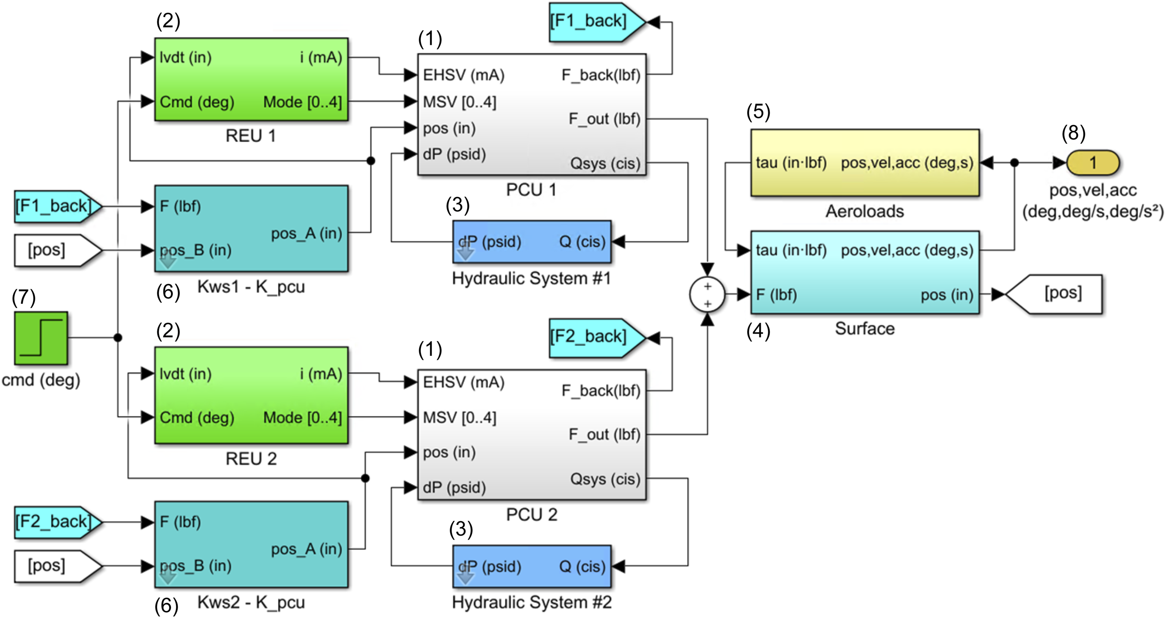
The variation of a design performance must be taken into account as early as possible to mitigate the development risk. Therefore, the design parameters are entered with their uncertainty or tolerance range, and the simulation of each requirement is done for three cases: minimum, nominal, and maximum performance.
Typically, the minimum performance verifies that the design and sizing comply with the performance requirements, and the maximum performance verifies the integration with the interfaces. For example, the minimum performance verifies compliance with the loaded rate requirements, and the maximum performance verifies compliance or specifies the structural environment loading.
The minimum, nominal, and maximum performances are obtained by setting up the simulation model with predefined combinations of the minimum, mean, and maximum design parameter’s values. For example, the maximum fluid viscosity and piston seal friction and the minimum servo valve rated flow contribute to the minimum actuator performance. Meanwhile, the minimum fluid viscosity and piston seal friction and the maximum servo valve rated flow contribute to the maximum performance.
This simulation model has been adjusted and validated by comparing its simulation results with a proven detailed design model from the system supplier. The detailed design model was validated by comparing its results with a hardware prototype tested during the actuation system’s qualification campaign.
Simulation tool achievements and limitations
The presented simulation tool efficiently sized and validated the conceptual design defined in the New Methodology Part 2: Conceptual Design section. It also enabled intensive sizing iterations to trade among the aircraft’s stability and control requirements, control surface aerodynamic characteristics, and actuation system impact. In this way, it enabled an aircraft-level optimization of the actuation system integration.
However, the simulation model includes many design parameters (65), requiring substantial expertise in actuator design and a good knowledge of the industry state-of-the-art. The model validation also requires system designer expertise. In other words, it does not replace the design expertise.
Methodology overview and discussion
In this section, the conventional preliminary design methodology is compared to the new one. To this end, Figure 12 illustrates the conventional (left) and redefined methodology (right) main steps and outcomes for both the aircraft manufacturer and the system supplier. Comparison between conventional and redefined methodology for the preliminary design of flight control actuation systems.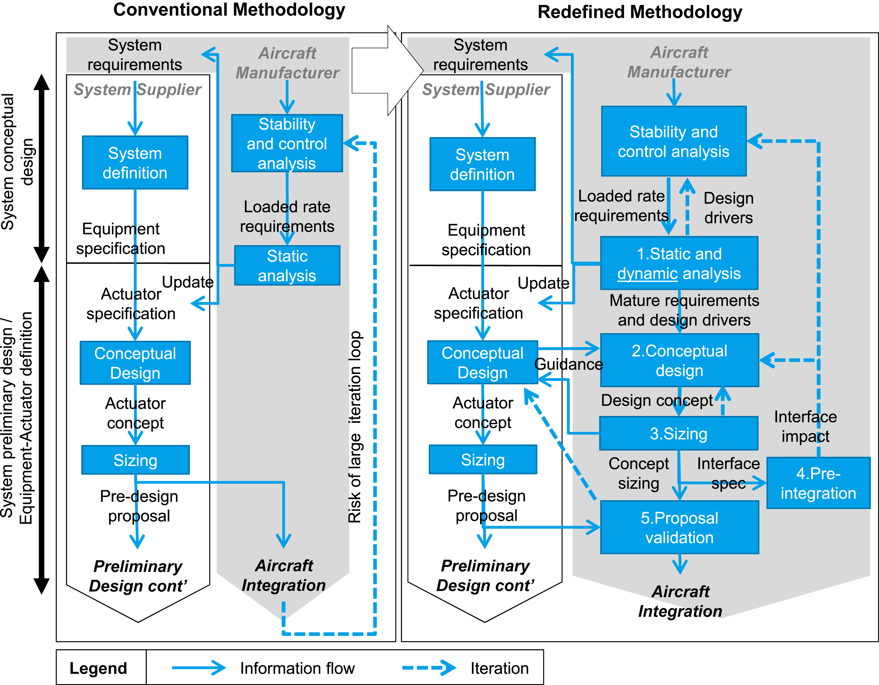
Conventional methodology
As described in the Conventional Approach section, the conventional methodology starts with an aircraft stability and control analysis by the aircraft manufacturer. The loaded rate requirements resulting from this analysis are benchmarked in a static approximation to ensure that they are within the expected range before passing them to the system supplier together with the other system requirements like the installation environment constraints and the flutter protection requirements. The system supplier proceeds to the system’s conceptual design and defines the equipment specifications. At this stage, we focus on the equipment specific to the system under study: the elevator actuator. The actuator concept is defined from the actuator specification, and its sizing is based on an open-loop simulation of the loaded rate requirements. This process is intensely iterative. Once the sizing is optimized and validated, the supplier proposes it to the aircraft manufacturer. The design comes with interface specifications, for example, structural loading and hydraulic power consumption. The aircraft manufacturer then begins integrating the proposed design into the aircraft. The integration aims to validate the proposed design at the aircraft level and approve the continuation of the actuator preliminary design, but it can lead to a large design iteration loop and a late revision of the system requirements. This risk increases with the lack of earlier iteration opportunity and conflicting requirement identification. Another issue is that the design is optimized at the system level and might not contribute to optimal aircraft design.
The situation reported in the Design Challenge: Actuator Oversizing section is an excellent example of how the drawbacks of the conventional methodology can lead to a development roadblock, mainly due to the lack of early iterations of system requirements and aircraft-level optimization.
Redefined methodology
The presented methodology redefines the aircraft manufacturer activity, and its addition is divided into five main parts: (1) static and dynamic analysis of the performance requirements (cf. the New Methodology Part 1: Requirements Analysis section), (2) conceptual design (cf. the New Methodology Part 2: Conceptual Design section), (3) sizing and concept validation (cf. the New Methodology Part 3: Sizing and Validation section), (4) pre-integration, and (5) validation of the supplier’s proposal. The static and dynamic analysis of the performance requirements ensures their maturation by identifying the design drivers and conflicting requirements. In this way, it is possible to focus on revising and refining the critical requirements. The results are mature requirements. In addition, the information on the design drivers and requirement conflicts gives the aircraft manufacturer the insight required to perform. A conceptual design toward an aircraft optimum: This activity is carried out in parallel to the system supplier’s work. At this stage, early information from the supplier’s conceptual design, for example, technology constraints, risks, and proven design solutions, contributes to orienting the aircraft manufacturer’s own conceptual design. The main difference between these concurrent activities comes from the supplier’s focus on system-level optimization and the manufacturer’s focus on aircraft-level optimization. The sizing is based on physical modeling and simulation and the model’s alignment and design parameters. Successful sizing validates the concept and provides interface specifications (e.g., stall load and max flow consumption), which initiates (4) preliminary integration and, eventually, an iteration to optimize the conceptual design for interface impacts. The validated concept and sizing can be used to guide the system supplier toward an optimal aircraft design. It is also the reference for (5) validating the supplier’s design proposal before continuing the preliminary design.
The redefined methodology significantly increases the involvement of the aircraft manufacturer in the system design. It adds early iteration opportunities and enforces design optimization at the aircraft level. In this way, it mitigates the risk of late and large iteration loops (i.e., it mitigates development delay, cost, and risk) and contributes to a more optimized aircraft product.
Case study application
In the studied case, the sizing of the initial actuator design proposed by the system supplier did not converge following a performance requirement update. The dynamic analysis revealed the design drivers and led the aircraft manufacturer to iterate on the aircraft aerodynamics’ stability and control requirements. It resulted in mature performance requirements. The provided insight led the aircraft manufacturer and the system supplier to innovate and develop an optimized design to address the conflicting requirements. The aircraft manufacturer’s sizing validated the new design and supported a preliminary integration with the actuation system interface stakeholders (aerodynamics, stability and control, structure, and hydraulics system). In this way, it was possible to guide the supplier based on an optimum aircraft objective. The obtained sizing validated the supplier’s proposal by comparison, and the close matching of the two sizings (difference of 2%) validated the new approach. The later successful integration and aircraft performance estimation validated the overall methodology. The final actuator design, represented in Figure 13 with its installation in the aircraft, illustrates the validation by matching the conceptual definition and sizing. Elevator actuator installation, based on Global 7500 aircraft maintenance manual (courtesy of Bombardier).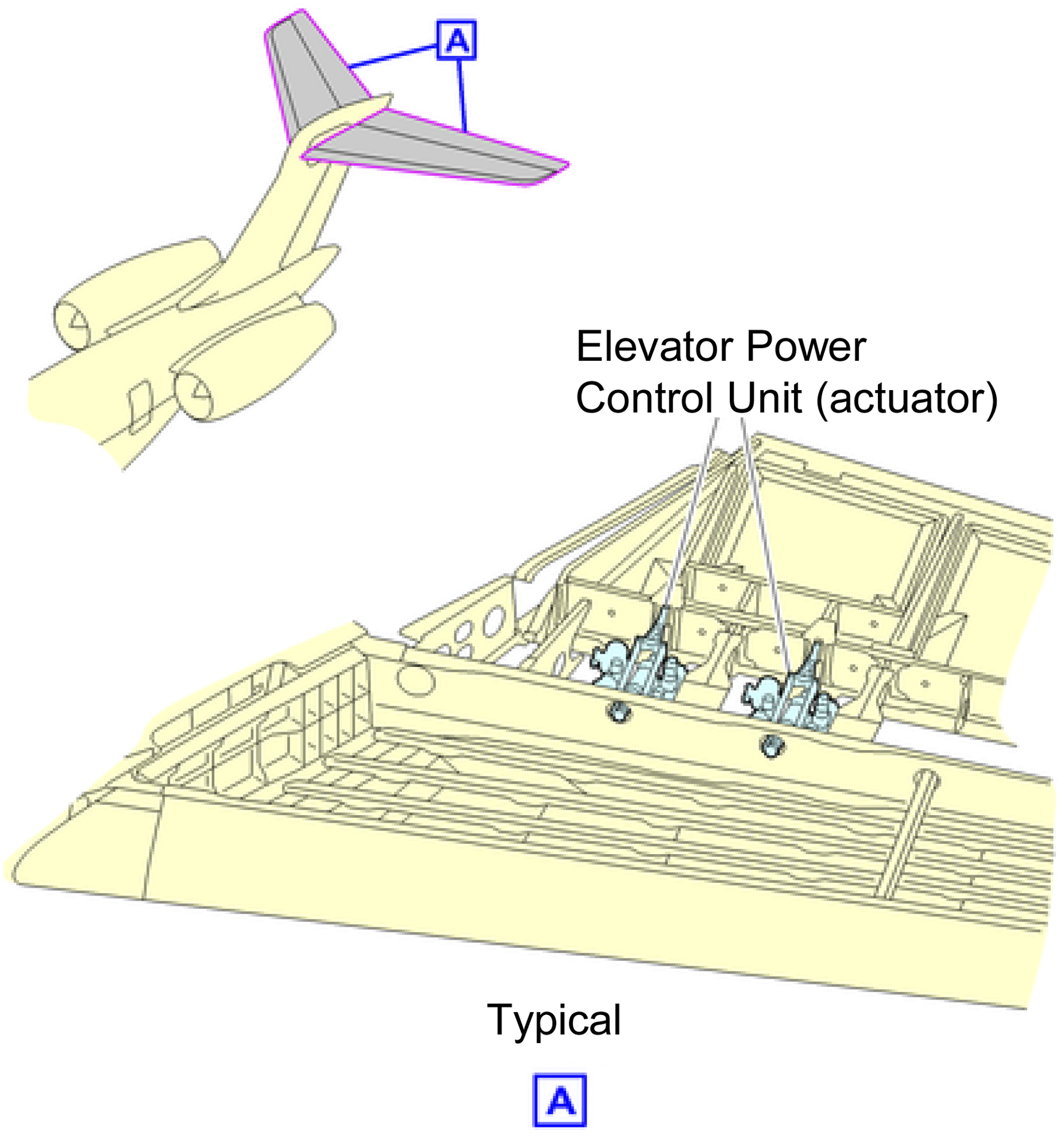
Limitations
The detailed design, out-of-the-scope of this article, revealed that the actuators’ actual damping response in the frequency domain is significantly different from the rigid fluid approximation in the time domain mentioned in the New Methodology Part 2: Conceptual Design section. It caused a revision of the saturated damping sizing late in the preliminary design. The consequence was minor, but it had the potential for a critical impact. Therefore, even if it does not invalidate the presented methodology and tools, the following question must be addressed as a priority in future work: How can the damping response in the frequency domain of a given conceptual design be estimated accurately with a low level of design definition?
Another issue appeared toward the end of the detailed design. In some critical cases, the hydraulic power supply capacity was lower than the conceptual design’s assumptions, critically affecting the actuation performance. Design changes were not made, but this highlighted the criticality of this input. Therefore, future work should consolidate the estimation of the hydraulic power supply in the conceptual design phase.
Conclusion
This article presented a model-based methodology redefining the aircraft manufacturer’s involvement in the preliminary design of flight control actuation systems. The presented methodology adds early analysis and iterations to mature requirements, providing design guidance and validation and thereby securing the development process by mitigating the risk of late and costly iterations. To this end, a novel modeling approach was introduced to analyze loaded rate requirements by simulating closed-loop performance with a generic nonlinear second-order state filter, including the main performance limitations without requiring a preliminary design definition. The methodology also addresses manufacturing and operational variations, in effect uncertainty, to further reduce development risk. Finally, it enforces design optimization at the aircraft level by implementing a pre-integration activity.
The case study of the fly-by-wire Global 7500 elevator actuation system provided in-depth insight into the complex design process of today’s fly-by-wire flight control systems. It also demonstrated the ability of the methodology to lead to innovative design to resolve a typical high-performance aircraft design challenge: conflicting performance requirements. The fact that the final actuator design matches its preliminary definition illustrates the ability of the methodology to mitigate late and costly design iterations.
A posteriori, the detailed design revealed weaknesses in the presented methodology: the conceptual assessment of the actuator damping response and the approximation of the hydraulic power supply. Inaccuracy in these aspects can lead to a redesign of the actuation system late in the detailed design phase. Therefore, future work should address the preliminary assessment of the damping response in the frequency domain and the hydraulic power supply assumptions in the conceptual design to consolidate the presented methodology.
Footnotes
Declaration of conflicting interests
The author(s) declared no potential conflicts of interest with respect to the research, authorship, and/or publication of this article.
Funding
The author(s) received no financial support for the research, authorship, and/or publication of this article.