
Abstract
A novel passive approach for controlling the flow in a 2D dynamic stall at variabl freestream is investigated. 2D computational fluid dynamics simulations of an SC1095 airfoil with surface-based trapped vortex generator (STVG) type passive flow control were conducted. The airfoil was exposed to a fluctuating freestream of Mach 0.537 ± 0.205 and Re = 6.1 × 10⁶ (based on the mean Mach number) and experienced a 10° ± 10° pitch oscillation with a frequency of 4.25 Hz. These conditions were selected as an approximation to the flow experienced by a UH-60A helicopter rotor airfoil section in an actual fast forward flight test case. The baseline simulations were cautiously validated with experimental data for both transonic flow and dynamic stall under the variable freestream. Then, 20 different local STVGs type geometry modifications were investigated as a means of passive flow control. Modifications were examined on both the airfoil’s upper and lower surfaces. Results showed that the STVGs were able to mitigate the negative effects of shock-induced dynamic stall. The best geometries could reduce the peak negative pitching moment by as much as 9–23% during the transonic phase of a cycle and by as much as 19–71% during the dynamic stall phase. Also, they were able to reduce peak drag by 8–20% in the transonic phase and by 15–44% in the dynamic stall phase. On the other hand, the lift-to-drag ratio was significantly increased by 3–28% per one rotor cycle. All the above advantages came at virtually no penalty in the lift.
Keywords
Introduction
The blades of a helicopter’s main rotor are subjected to fluctuating relative freestream due to the combination of the rotor rotational speed as well as the helicopter’s forward flight speed. Along with the need to introduce cyclic pitching motion to redistribute the forces over the rotor disk, a blade airfoil section will experience complex unsteady flow due to the instantaneous variation of the freestream Mach number and the effective angle of attack. 1 These conditions will generate unsteady dynamic loads represented by the hysteresis of the integrated aerodynamic coefficients within one revolution. The mixture of all these effects leads to the emergence of excessive vibrations in the main rotor hub as well as the control system of the helicopter. This not only deteriorates crew and passenger comfort but also restricts the forward flight speed of the helicopter.2–4
At moderate and fast advance ratios, the amplitude of the relative freestream fluctuation can be as high as Mach 0.3, the amplitude of the angle of attack as high as 10°, and all these occur at a high rotational frequency, that is, at about 3∼5 Hz. Hence, the advancing side of the rotor disc will be subjected to transonic flow and the retreating side to dynamic stall within the same cycle.
It is clear from the above that controlling this harsh environment flow via a simple, reliable, lightweight, and blade-based control system would be highly desirable. Several rotor-based active flow control systems have been proposed in the past two decades, such as the active twist rotor,5,6 active pitch link,7,8 actively controlled flap, 9 pulse jet actuators, 10 as well as structural control systems, such as active stiffness control. 11 Although many of these systems have been demonstrated to be quite promising, due to their complexity, weight, and/or reliability, these systems have not yet found their way through to industrial application. A hub-mounted vibration suppressor system, where two eccentric masses are applied in out-of-phase rotation, has been successfully flight-tested recently and is anticipated to be applied on production helicopters. 12 Several fuselage-based active control systems have been established too; yet, these cannot address the problems of vibration and noise of the blades and are naturally considerably heavier than rotor-based systems. 13 Semi-passive flow control systems have also been proposed, for example, the backflow flap of Ref. 14.
Moreover, all the above active flow control systems were designed based on dynamic stall models, which assumed constant freestream Mach number, without accounting for the fluctuations in the relative freestream in real forward flight, and without considering the possible interaction between the transonic flow on the advancing side of the rotor and the dynamic stall on the retreating side of the rotor.
Recently, Al-Jaburi et al. 15 proposed 26 different novel geometries for minimizing the negative effects of dynamic stall on the retreating blades of helicopters in forward flight. The proposed geometries acted as a means of passive flow control and were analyzed via computational fluid dynamics (CFD) under constant freestream Mach number. Results showed that the upper surface modifications were able to mitigate the negative effects of dynamic stall better than the lower surface ones.
The best upper surface modifications were able to reduce the peak negative pitching moment by about 50–60% and peak drag by 30–40%, at the expense of sacrificing only 2–10% of peak lift. These results were comparable to the effects of an actively controlled flap but without the complexity of implementing moving surfaces in a high-centripetal force dominated environment. On the other hand, the lower surface modifications have the ability to increase the maximum lift by as much as 16% with a minor penalty in pitching moment and drag.
The advantage of the passive flow control concepts proposed in Ref. 15 is that they affect the airfoil characteristics only close to the maximum angle of attack range, while largely maintaining the airfoil’s original behavior at the lower angles of attack. This makes the proposed concepts a potential alternative for rotary-wing flow controls, where the implementation of active flow control technologies is not trivial due to the large centripetal forces and limited space.
Thus, the present article aims to investigate via CFD the feasibility of Al-Jaburi et al. 15 novel passive flow control systems for the mitigation of the negative effects of the shock-induced dynamic stall under fluctuating freestream Mach numbers.
To the knowledge of the authors, no other article has investigated such passive flow control techniques for shock-induced dynamic stall under fluctuating (variable) freestream previously, and as such, this article presents original results.
Test cases
Simulation parameters and conditions.
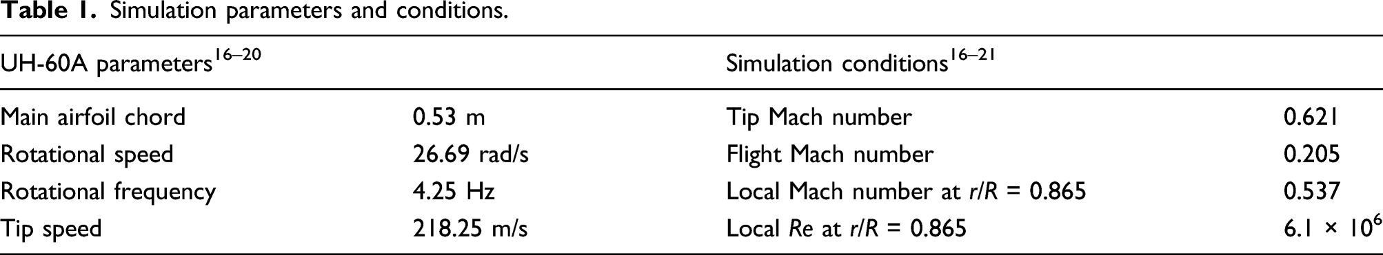
The angle of attack time history for the selected advance ratio and blade section can be described according to Kerho,
23
who based on the data of Bousman
24
predicted the blade pitching history of UH-60A using CAMRAD II, a comprehensive rotorcraft analysis code. According to Kerho,
23
a sinusoidal function of 10° − 10° sin (Ωt) can be seen as an appropriate estimation for the actual angle of attack history (Figure 1). Hence, this is used in the present article too.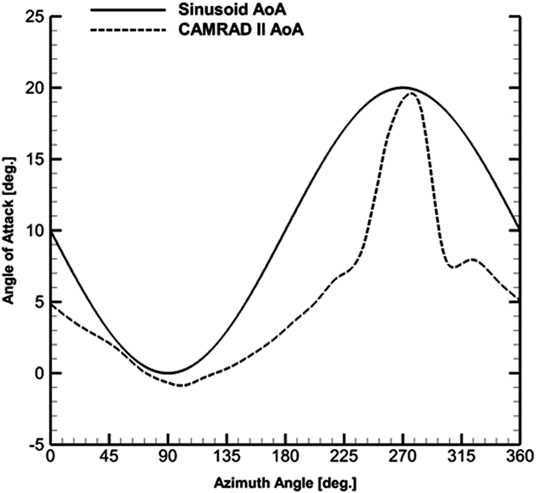
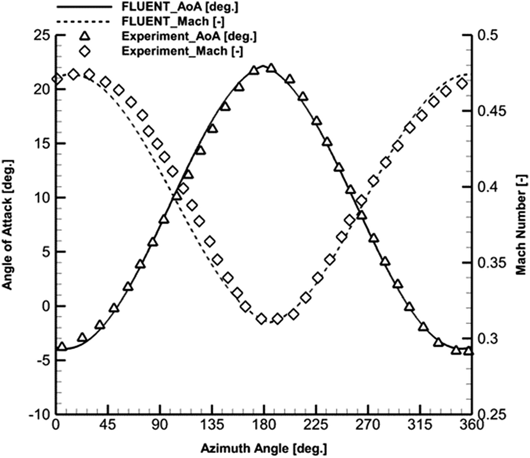
From Table 1, the Mach number fluctuation shall be set to 0.537 ± 0.205. Equations (1) and (2) describe the combined time variation of the angle of attack and the relative Mach number, with the resulting time histories shown in Figure 2 Angle of attack oscillation versus freestream Mach number fluctuation used in the simulations depicted as a function of the azimuth angle. Reproduced from Ref. 16.

As one can see from Figure 2, there is a phase difference of 180o between the angle of attack and the fluctuation of the freestream Mach number.
Airfoil geometry
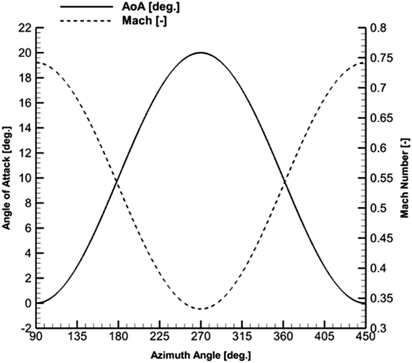
As it was mentioned earlier, the present study imitates those flight conditions, which a UH-60A main rotor blade section at r/R = 0.865 would experience at Mach number 0.205 forward flight speed. The main rotor blade of UH-60A consists of two airfoils, the SC1095 and SC1094 R8.
25
At r/R = 0.865, the airfoil is the SC1095 (Figure 3); hence, this was designated as the baseline airfoil for this study. UH-60 A main rotor blade and SC1095 airfoil (Ref. 25).
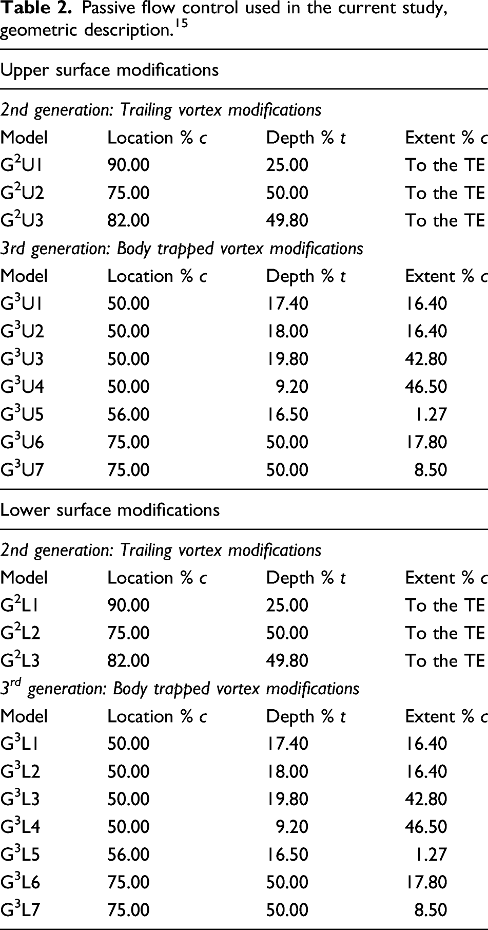
Passive flow control used in the current study, geometric description. 15
Numerical method setup
The fluctuating freestream methodology proposed in this work was previously validated by Al-Jaburi et al., 16 in which main points will be summarized here later. The fluctuating freestream was created by introducing a variable Mach 0.537 ± 0.205 at the domain inlet. More details on how this fluctuation was introduced are provided in Al-Jaburi. 17 It was expected that this case will produce transonic flow at the maximum of the Mach number, and consequently, it presents the possibility to examine how would the passive flow control systems of Ref. 15 affect both the transonic flow and ddynamic stall within one rotor cycle.
The code used for all simulations was the ANSYS Fluent solver. This solves the unsteady Reynolds Averaged Navier-Stokes (URANS) equations, which are discretized via a Finite Volume Method (FVM) with second-order accuracy in space. An implicit time integration method was chosen for the time derivatives, yielding second-order accuracy in time. Although the SST k-ω turbulence model is typically more accurate than the one-equation Spalart–Allmaras (SA) model, when simulating constant freestream dynamic stall, 26 it was found by Klein 27 and Al-Jaburi et al. 15 that it produces two extra peaks in the aerodynamic coefficients (C l , C d , and C m ) around the peak angle of attack. These seem to happen due to the SST k–ω turbulence model generating nonphysical vortices.
Hence, the SA turbulence model was selected for all simulations in this study, which is expected to capture the flow physics at a reduced computational cost as well. The one-equation SA turbulence model demonstrated to be efficient and robust for a range of 2D airfoil flows with considerable flow separation.23,28,29
The computational domain design and reconfiguration (and also the explanations) were discussed in detail in Refs. 16 and 17. The current domain is rectangular, with 1000c by 520c size (with the inlet fixed at 20c) and with the airfoil positioned in the middle of the rotating domain. A sliding mesh technique was utilized, and thus, a circular domain of 20c diameter rotating domain is situated inside the fixed rectangular domain. This is permitted to introduce the angle of attack variation. Figure 4 illustrates a sketch of the domain utilized in the current research.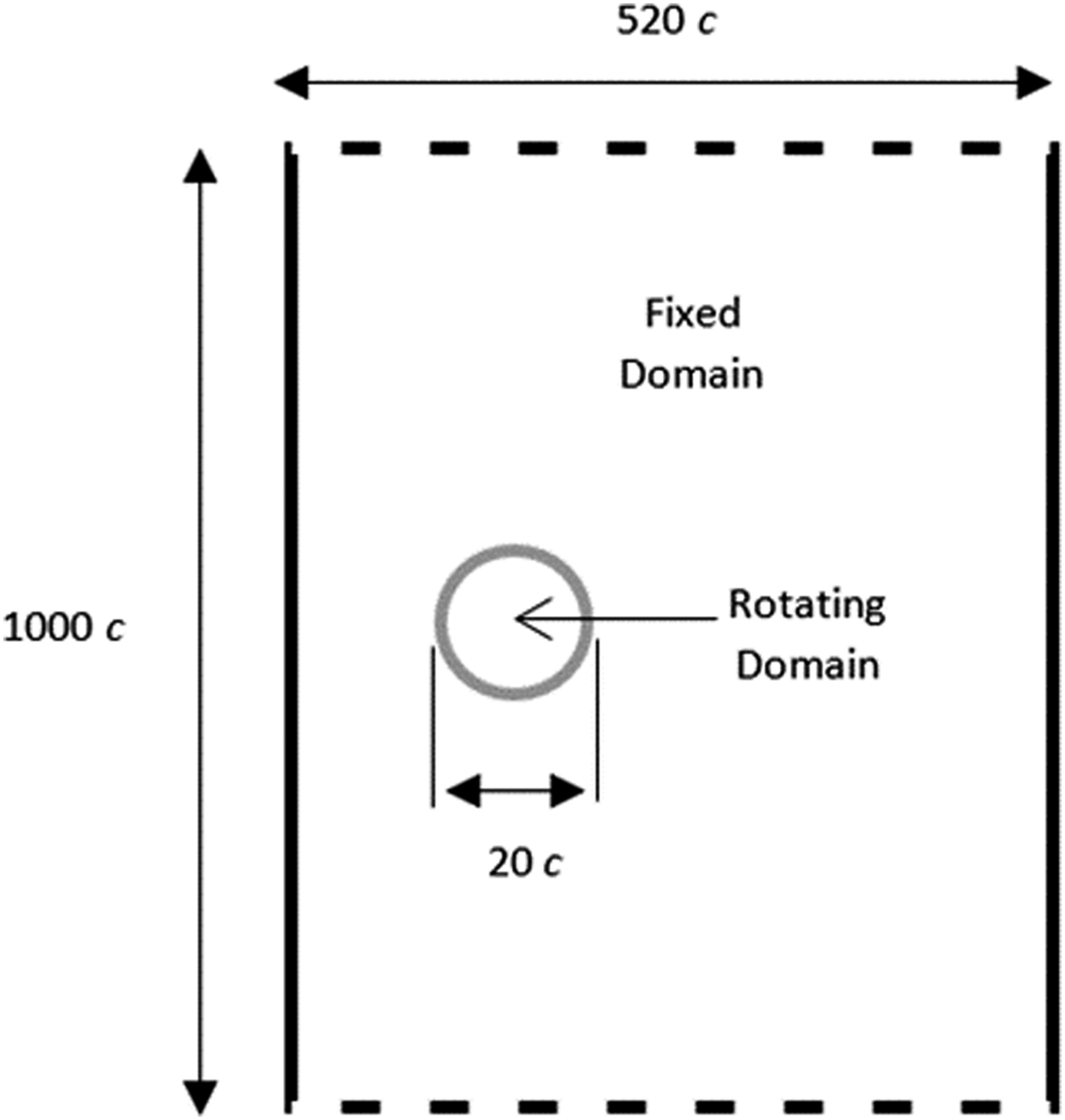
It is worth mentioning that since the velocity modifications at the inlet boundary take time to transmit to the airfoil, the resulted velocity profile at the airfoil location was shifted relative to that at the inlet because of wave progressing time delay. Al-Jaburi16,17 provides a detailed description of how to address the time difference accurately. The same approach was used in the current study.
The computational mesh generation techniques used in Refs 16 and 17. were also adopted in the current study. The current mesh has an overall of 252,321 cells with 650 cells forming the airfoil surfaces. A structured rectangular mesh was utilized in the “inflation layer” surrounding the airfoil, to accurately capture the boundary layer. The structured mesh consists of 40 layers forming the inflation layer. The inflation layer was carefully designed to have y
+
below 1. Consequently, there was no need to use the wall function in the SA turbulence model. Outside of the inflation layer, an unstructured mesh of 2D triangles was constructed to form the rest of the domain mesh. The unstructured mesh was refined in the vicinity and downstream of the airfoil, as shown in Figure 5, where it is expected to have both the transonic shock wave and dynamic stall vortices.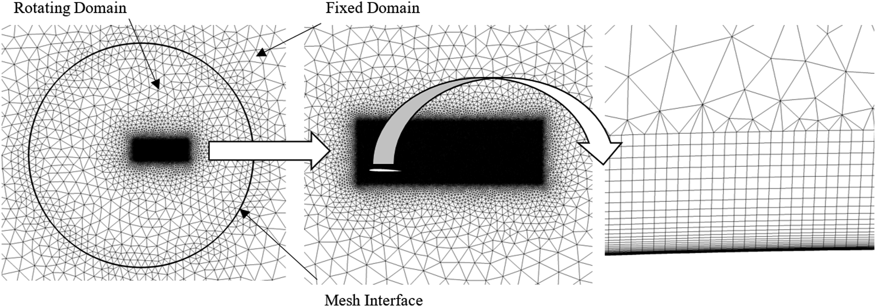
Using 2000 time steps per one pitching cycle, with an inner iteration of 100 steps between each consecutive time steps and a fixed Courant number of 200, the time step independence was achieved for the simulations. It is also worth noting that a residual value of 10−4 was specified for all the simulations in the current study.
Using this mesh and with the help of the steady-state flow initialization technique, no initial transient was needed.16,17 Verification of the numerical setup was conducted via an in-depth grid-dependence study. Full details of the verification tests are available in Refs. 16 and 17.
Two validation processes were used to evaluate the ability of the current mesh in capturing both the transonic shock on the advancing helicopter blade as well as the dynamic stall phenomenon on the retreating blade. In the first validation, a transonic steady flow simulation of an SC1095 airfoil exposed to Mach number 0.8 and Reynolds number of 5.65 × 10⁶, under angles of attack of 2.1° and 6.2°, respectively, was compared to the experiment of Ref. 30. Figure 6 provides the pressure coefficients at these angles of attack. For the second validation, dynamic stall simulation under fluctuating freestream conditions was compared to experiments found in Ref. 31. The validation, in this case, involves an experiment of an SSC-A09 airfoil experiencing a fluctuating freestream dynamic stall, with the reduced frequency of 0.05, for the simultaneous pitching oscillation of 8.5° ± 13° and Mach number fluctuation of 0.4 ± 0.08.
31
Although the Mach number amplitude (0.08) used in this experiment was very low compared to that of the current study (0.205), it was decided to be used for validation because up to now, this was the only experiment that comprises dynamic stall illustrative of helicopter forward flight with some reasonable freestream fluctuation. Moreover, the frequency of pitch and Mach number variations (up to 17 Hz) is representative of helicopters.
31
Figures 7–9 demonstrate the outcomes of the complete validation process. Transonic flow validation with Ref. 30. SC1095 airfoil, Re = 5.65 × 10⁶ and M = 0.8. Validation of the fluctuating freestream conditions at the airfoil leading edge with the experiments of Ref. 31. Re = 3 × 10⁶, Δφ = 13.3°, k = 0.05, α = 8.5 ± 13, and M = 0.4 ± 0.08. Dynamic stall under constant freestream validated with Ref. 31. SSC-A09 airfoil, Re = 3×10⁶, k = 0.05, α = 8.5 ± 13, and M = 0.4. Dynamic stall under fluctuating freestream validated with Ref. 31. SSC-A09 airfoil, Re = 3×10⁶, Δφ = 13.3o, k = 0.05, α = 8.5 ± 13, and M = 0.4 ± 0.08.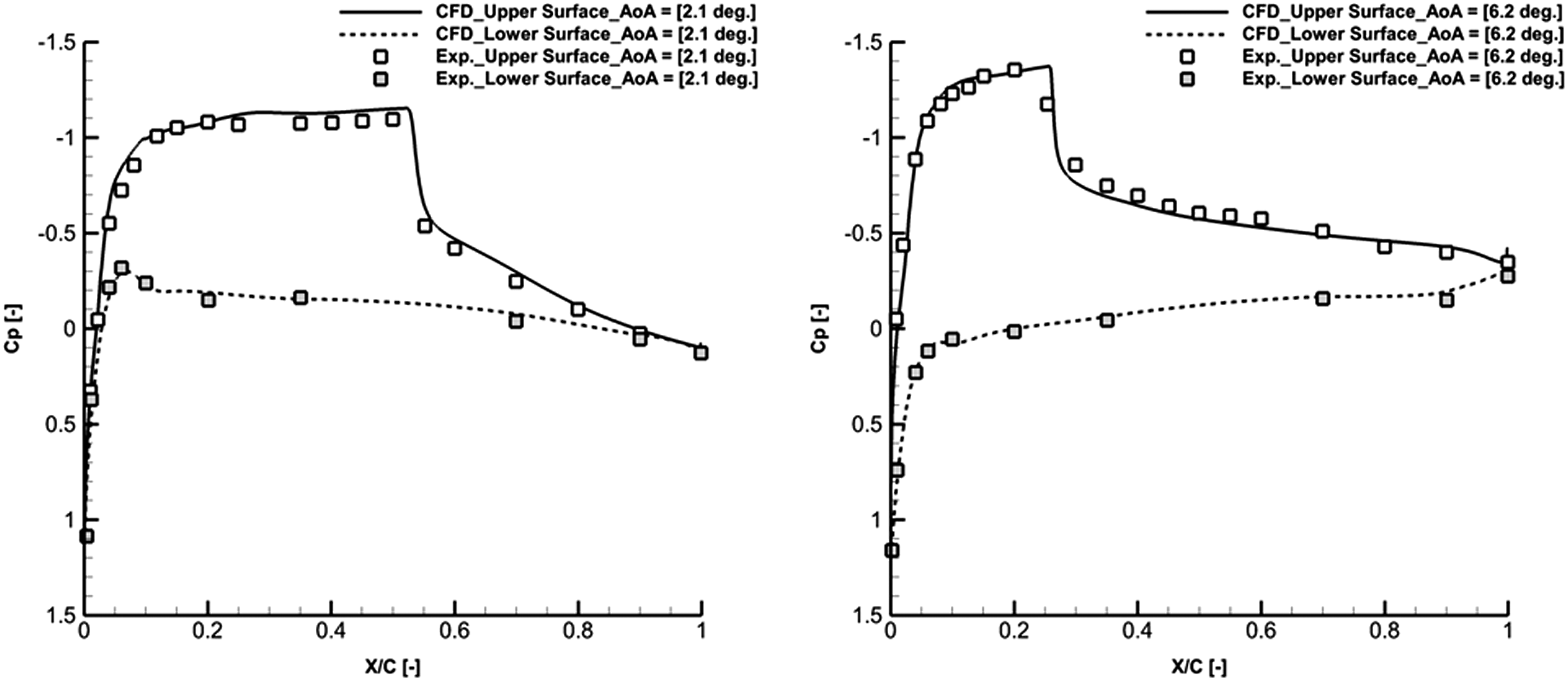
As illustrated in the figures, the simulations matched the experimental data very well using the proposed mesh, except the anticipated pitching moment overshoots in the values of the peak of the hysteresis loops, as well as the divergence in the downstroke, as shown in Figures 8 and 9. However, these are very common in the dynamic stall literature and are most likely related to the turbulence model used. Hence, the baseline mesh was considered to be satisfactory enough for simulating shock-induced dynamic stall over both the baseline airfoil and with the implemented passive flow control geometry.
Results and discussions
The SC1095 airfoil with 20 STVG variants was studied via CFD simulations for 2D shock-induced dynamic stall control. According to Al-Jaburi,16,17 unlike the typical, constant freestream dynamic stall, compressible dynamic stall under fluctuating freestream has two phases: a transonic phase and a dynamic stall phase. Hence, several parameters were chosen to assess the performance of the airfoil with modification. These parameters were (a) the peaks of the lift-to-drag ratio, drag, and pitching moment coefficients (C l /C d , C d , and C m ), for both the transonic and dynamic stall phases, and (b) the average values of the aerodynamic coefficients (C l /C d , C d , and C m ) over one rotor cycle. The latter choice was made because the current 2D study—naturally—disregards the 3D effects of the helicopter main rotor blade aerodynamics, that is, crossflow, Coriolis forces, and tip vortices. It is believed, however, that the averaged values of the aerodynamic coefficients over one rotor cycle provide a reasonable evaluation of the aerodynamic performance and loads of the blade section. Thus, the average values over one rotor cycle will also be used to evaluate the performance of the proposed passive flow control techniques.
The objective of the present work was to design a passive flow control concept, which can serve as a viable alternative to active flow control techniques; due to its simplicity, it should have the promise of easier implementation in practice. The intended passive flow control technique should not deteriorate the lift characteristics of the original airfoil significantly while providing noteworthy improvements in drag and pitching moment reductions, that is, it should decrease peak drag and peak negative pitching moments. Reducing the pitching moment is desired since this exhibits vibration in the pitch links during forward flight.
All simulations were completed with the numerical parameters described above for the UH-60A test case at 0.865 blade radius, that is, f = 4.25 Hz, Re = 6.1×10⁶, M = 0.537 ± 0.205, and α = 10° ± 10°.
Summary of the computational fluid dynamics simulation results for the SC1095 at f = 4.25 Hz, Re = 6.1×10⁶, M = 0.537 ± 0.205, and α = 10° ± 10°. All results are compared to the baseline airfoil.
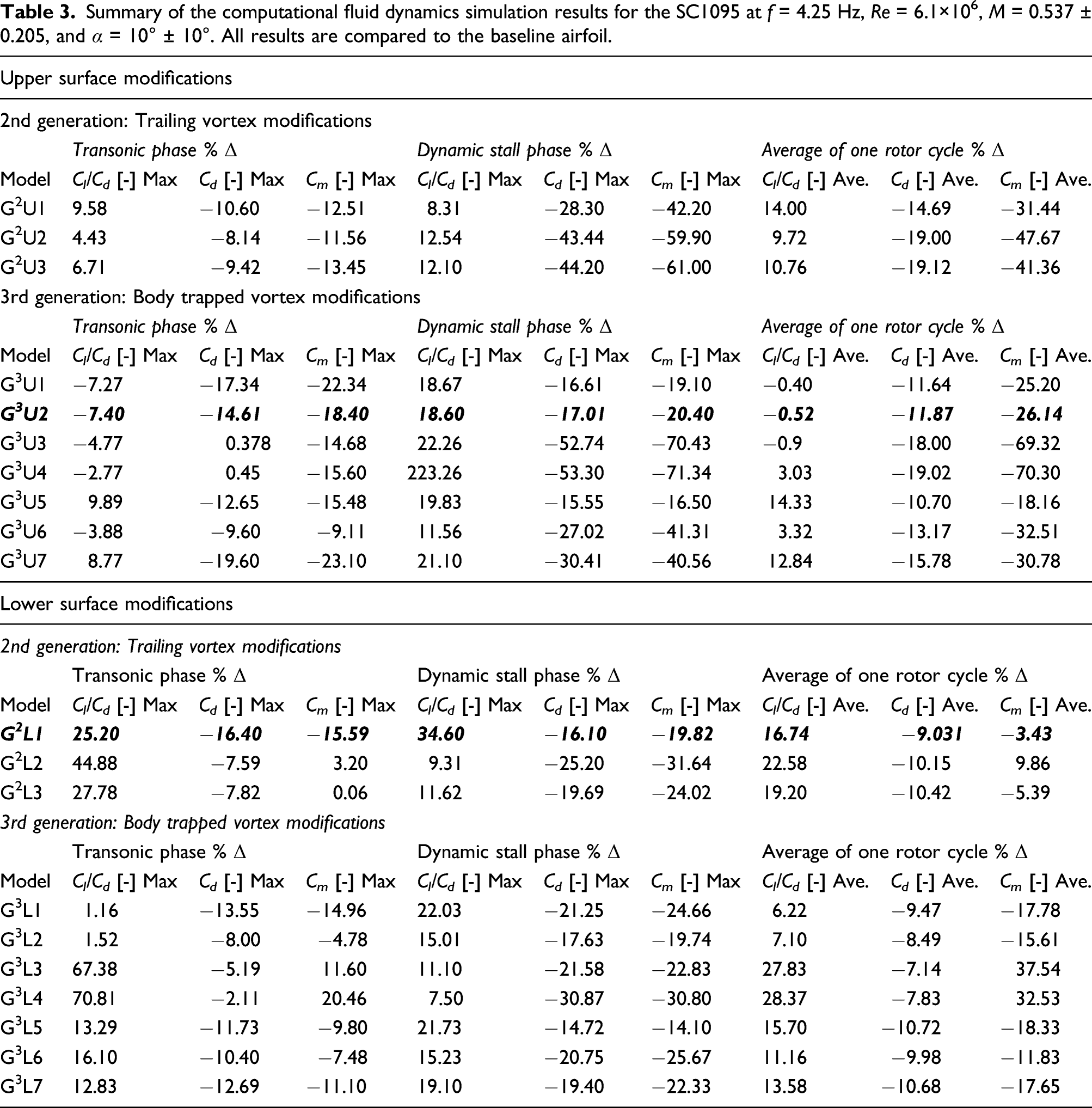
The averaged results over one rotor cycle confirm the potentials of the proposed passive flow control technique to enhance the performance of the helicopter main rotor as can be seen from Table 3.
The flow physics behind these results were explained by the detailed analysis of the flow by means of flow visualization comparisons between the baseline airfoil and the modified airfoil. However, due to space constraints, only two modifications were analyzed, G3U2 and G2L1. Those two modifications were chosen for the sake of comparison. The same modifications were arbitrarily selected in Ref. 15 for the application of the STVG in a constant freestream dynamic stall condition. In the work presented in Ref. 15, the baseline airfoil was the symmetrical NACA 0012 airfoil exposed to a constant freestream of Mach 0.3 and Re = 3.76 × 10⁶ and undergoing a 15° ± 10° pitch oscillation (deep stall) with a frequency of 5.4 Hz was used. However, for the current work, the baseline airfoil is the transonic, real helicopter, SC1095 airfoil, and it is exposed to a fluctuating freestream of Mach 0.537 ± 0.205 and Re = 6.1 × 10⁶ and experiences a 10° ± 10° pitch oscillation with a frequency of 4.25 Hz. Therefore, the comparison was necessary to prove that the proposed STVG is applicable for different airfoils, subjected to totally different flow regimes. The airfoils, for which detailed analysis is provided, are pointed by bold and italic font in Table 3.
SC1095 airfoil with G3U2 modification
The G3U2 flow control modification was developed after an extensive optimization, in which the objective was to decrease shock-induced drag during the transonic phase, as well as to control vortex shedding during the dynamic stall phase via the interaction between the vortex trapped inside the STVG cavity and the dynamic stall vortex over the airfoil upper surface.
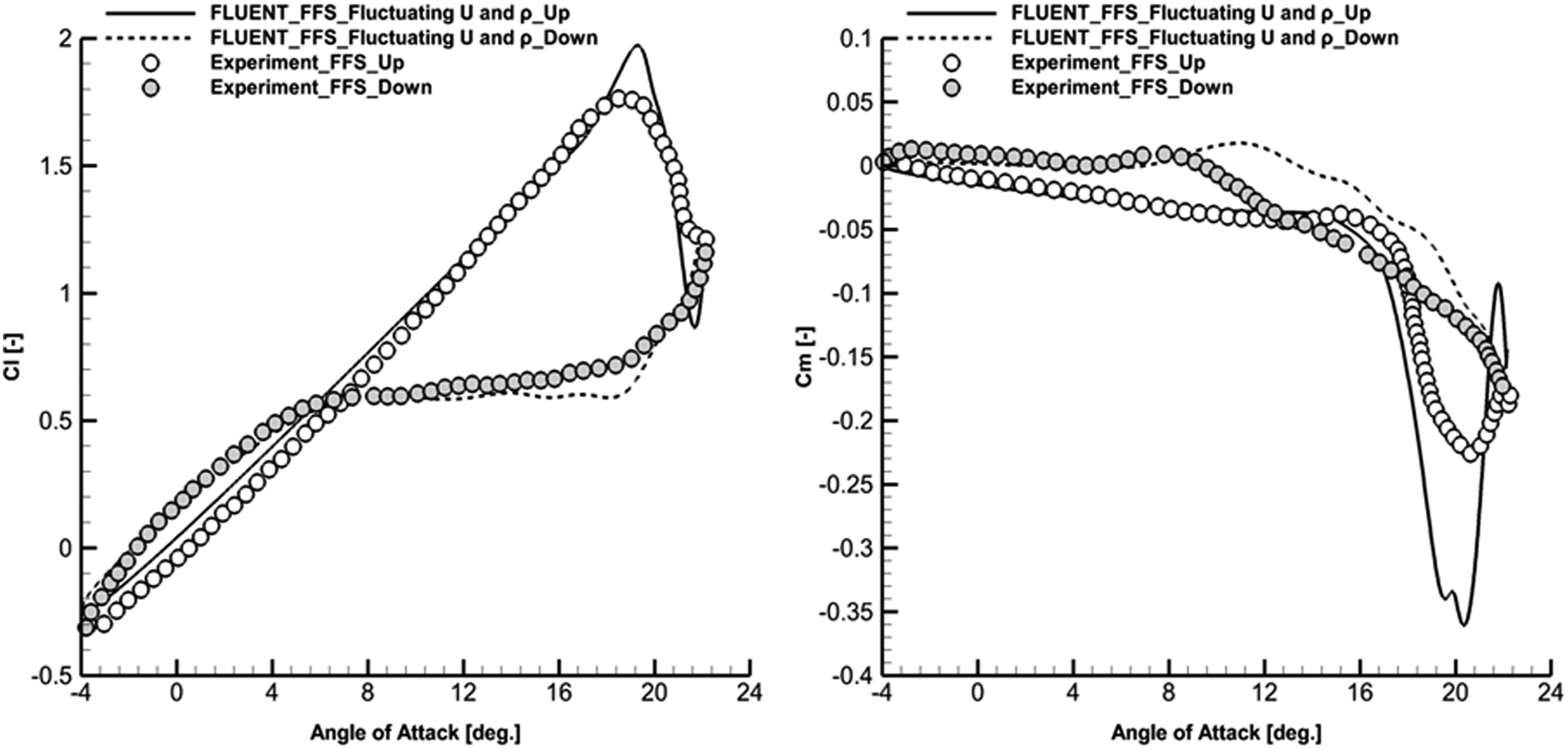
The airfoil has the modification installed at 50% c with a depth of 18% t and length of 16.4% c toward the trailing edge. Figure 10 shows the outline of the SC1095 airfoil with the G3U2 modification, while Figure 11 displays the aerodynamic coefficients. Figure 12 provides a comparison between constant and fluctuating freestream dynamic stalls during the upstroke phase. Finally, in Figure 14, the pressure coefficient and the Mach number contours superimposed by vorticity are shown. SC1095 airfoil with G3U2 passive flow control modification. Aerodynamic loads SC1095 airfoil with G3U2 modification. M = 0.537±0.205, f = 4.25 Hz, Re = 6.1 × 10⁶, and α = 10° ± 10°. Mach contours. SC1095 airfoil, M = 0.537 (upper) and 0.537 ± 0.205 (lower), Re = 6.1×10⁶, f = 4.25 Hz, and α = 10° ± 10°.
First, let us observe the peculiarities of the flow due to the fluctuating nature of the freestream. Note from the flow visualization plots in Figure 12 that during the upstroke phase, AoA 5°, for example, the flow is still attached in the constant freestream dynamic stall compare to that in the fluctuating freestream. Unlike for constant freestream dynamic stall, where flow separation occurs only beyond the static stall angle of attack (typically beyond 12°), for the fluctuating freestream case, the flow separation is present from the beginning of the upstroke phase (5°–20°). Flow separation occurs due to the shock wave boundary layer interaction at transonic speeds (Figure 13 and frames B–E in Figure 14, corresponding to AoA 5°–12°). The vorticity plots clearly illustrate the regions of boundary layer separation. As a result of this, the airfoil effectively enters the “dynamic stall” dominated phase already with a massive flow separation of the upper surface (Frame F in Figure 14). Then, a dynamic stall vortex appears to be formed on Frame G, followed by the classical trailing edge vortex in Frame H. Mach number and vorticity contours indicating the separation and vorticity regions over the airfoil upper surface for selected frames during the upstroke phase. SC1095 airfoil with G3U2. M = 0.537 ± 0.205, f = 4.25 Hz, Re = 6.1 × 10⁶, and α = 10° ± 10°. Pressure coefficient and Mach number contours superimposed with maximum instantaneous vorticity lines (white dashed boundaries) for the SC1095 airfoil and SC1095 with G3U2. M = 0.537±0.205, f = 4.25 Hz, Re = 6.1 × 10⁶, and α = 10° ± 10°.
The effect of the STVG appears to be that during the transonic phase, it changes the pressure distribution on the upper surface in a favorable way (see Frames C–E in Figure 14). Note that a larger portion of the airfoil surface is exposed to low pressure. This causes a lift increase (see Figure 11, points C–E). This effect is in line with the observations made for the same STVG geometry for constant freestream transonic flow in Al-Jaburi.
17
At the same time, this leads to lower drag likely due to the lower height of the separated region (Frames C–D in Figure 14). And, since the pressure is redistributed in a way that its resultant force acts more forward, pitching moment decreases as well (see Frames C–D again). All these effects can also be seen as the lift curve being shifted by about 1.5° phase delay relative to the clean airfoil. During the dynamic stall phase, the 1.5° phase delay is maintained throughout the rest of the cycle for lift (Frames G–H), while a (favorable) decrease in drag and pitching moment can be observed.
An important effect of the modification was to generate a weaker shock wave during the transonic phase 17 (see the pressure plots of Frames A, B, and K in Figure 14) and to shift the peaks in the hysteresis loops by approximately 1.5° later when compared to the original airfoil. This causes the first and second stall events of the modified airfoil to happen with a delay in comparison to the baseline airfoil. For example, the first stall event, which is due to shock-induced boundary layer separation, combined with the increase in the angle of attack happened at an angle of attack of 10.5° for the modified airfoil, while it was 9° for the baseline airfoil (Figure 11).
The last portion of the upstroke phase (Frames G–H), along with the beginning of the downstroke phase, (Frames I–K) is dominated for both airfoils by shedding of multiple vortices, which is associated with the oscillations in the aerodynamic loads in Figure 11. The average loads of the modified airfoil over a rotor cycle are given in Table 3. Note that—over one rotor revolution—the lift-to-drag ratio remains virtually unchanged (a reduction of −0.5% only) while drag is reduced by 12% and pitching moment by as much as 26%, a very promising result overall.
SC1095 airfoil with G2L1 modification
As have been shown in Ref. 17, lower surface modifications have the ability to increase the lift-to-drag ratio for the full range of angles of attack by increasing the pressure on the lower surface of the airfoil, where the modification is implemented.
17
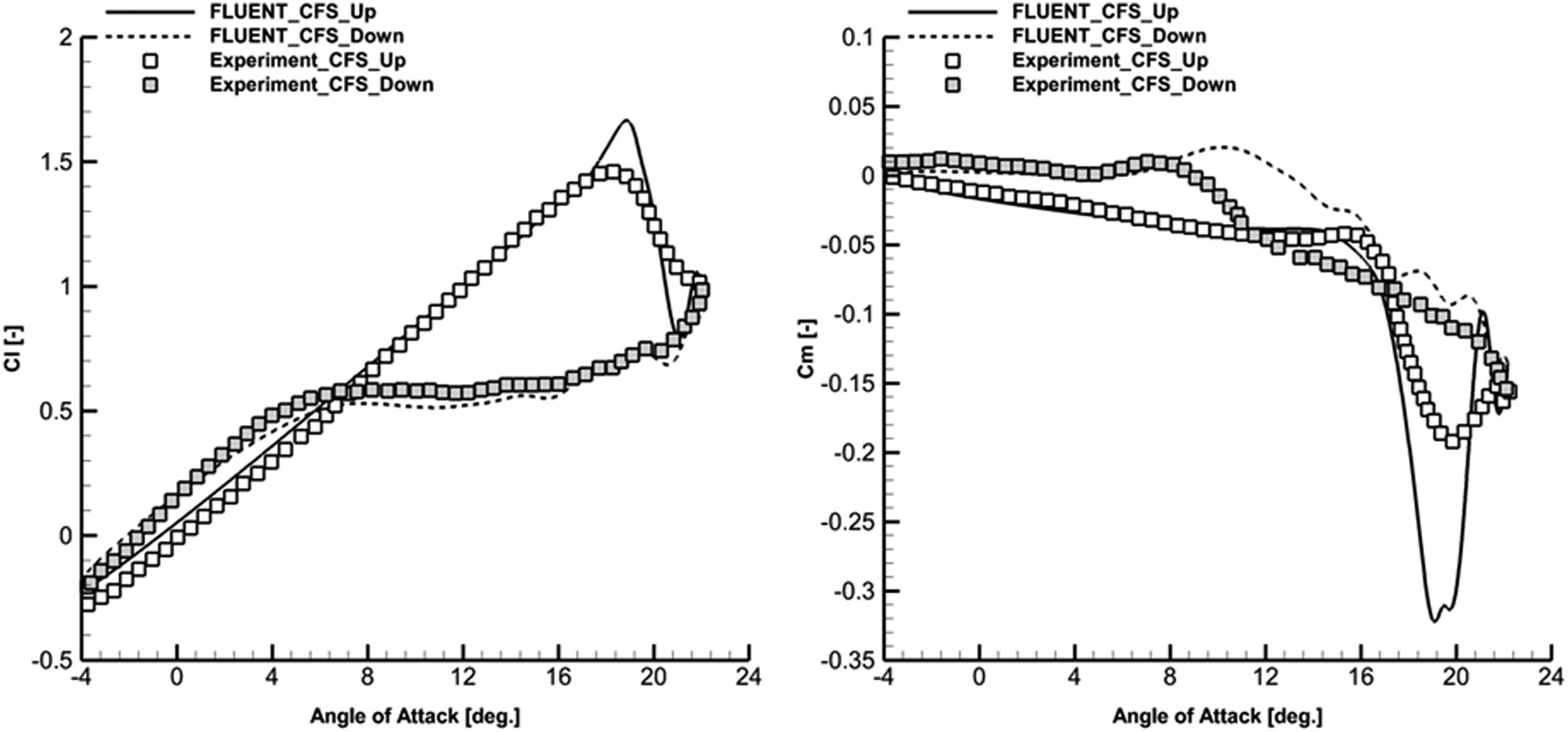
Several designs have been proposed; in the current article, the results for the G2L1 type will be discussed. This had the STVG placed near the trailing edge on the lower surface. The STVG geometry is a small step-like shape, starting at 0.9c. The location was dictated by structural design considerations: the smaller the modification, the better from a structural point of view. The cavity is extended to the trailing, for example, and its depth is 0.25 t (relative to the local thickness where the modification starts). Figure 15 illustrates the geometry. SC1095 airfoil with G2L1 passive flow control modification.
Figure 16 provides the aerodynamic coefficients of the modified airfoil compared to that of the baseline airfoil. From this, it can be seen that the G2L1 modification outperforms the baseline airfoil in terms of lift as well as the lift-to-drag ratio for both the transonic and dynamic stall phases. It also decreases the drag and the nose down pitching moment during both phases. Aerodynamic loads SC1095 airfoil with G2L1 modification. M = 0.537±0.205, f = 4.25 Hz, Re = 6.1 × 10⁶ and α = 10° ± 10°.
This time, the STVG appears to cause an opposite overall effect in comparison to the previous case. Instead of delaying events by 1.5°, it causes them to appear earlier by about 1°. This appears to be certainly true for lift and drag during the upstroke.
Examining the flow mechanism, again, the same major flow features are present as for the previous case. In the transonic phase, however, the increase in lift is likely not due to modifying the upper surface flow, but the lower one. Here, the pressure appears to rise within the cavity, causing a larger difference between the upper and lower surface, hence leading to increased lift (see the pressure distribution of Frames A–F in Figure 17). This observation is in accordance with Ref. 17. Pressure coefficient and Mach number contours superimposed with maximum instantaneous vorticity lines (white dashed boundaries) for the SC1095 airfoil and SC1095 with G2L1. M = 0.537 ± 0.205, f = 4.25 Hz, Re = 6.1 × 10⁶, and α = 10° ± 10°.
In the dynamic stall phase, the same effect dominates: although a dynamic stall vortex and trailing edge vortex are created, as usual, they are counterbalanced by a high-pressure region on the lower surface, thus increasing lift and decreasing the nose down pitching moment (see Frames G–H in Figure 17).
Despite the high oscillation frequency (4.25 Hz) and the fluctuating freestream, the modified airfoil succeeded in favorably augmenting lift, reducing both drag and pitching moment during the upstroke and downstroke phases, at virtually no penalty as shown previously in Table 3.
Conclusions
A novel and easy to implement passive flow control concepts were investigated via CFD for mitigating the negative effects of shock-induced dynamic stall on the blades of helicopter main rotors in forward flight. The concepts based on preceding studies were conducted by the same authors for dynamic stall under constant freestream conditions and transonic flow. The idea was to create a cavity in one of the airfoil surfaces, through which it will generate a “trapped vortex” inside it, thus redistributing the pressure around the modified airfoil surfaces. The novelty of the work is both in the application of such passive control techniques as well as carrying out the investigations at fluctuating freestream conditions.
During shock-induced dynamic stall, the blade will be subject to a transonic flow on the advancing side and dynamic stall on the retreating side; the two phenomena occurred at a very high frequency. The benefit of the method is that it affects the airfoil characteristics at both the transonic and dynamic stall phases. The proposed concepts were able to reduce drag and peak negative pitching moments (i.e., vibration) and at the same time to increase the lift-to-drag ratio at both phases of the cycle when compared to the baseline airfoil. This makes the concepts a viable alternative for rotary-wing active flow control, where the application of active flow control technologies is challenging due to the large centripetal forces and limited spaces in the rotor hub or inside the blade.
Twenty different geometries were examined via CFD. The results showed that both the upper and lower surface modifications were able to mitigate the negative effects of the shock-induced dynamic stall. Besides providing benefits in the peaks of the aerodynamic loops, the average of aerodynamic loads per one rotor cycle was also examined as a mean to assess the performance of the modified airfoil with passive flow control. Per one cycle, the average values of lift-to-drag ratio increased by 3–28%, drag decreased by 11–19%, and pitching moment decreased by 3–70%, at virtually no penalty in the lift. These results are important for designers (i.e., blade performance analysis and pitch link structural design) and are comparable to the effects of active flow controls but without the complexity of implementing moving surfaces in a high-centripetal force dominated environment.
The existing flow control concepts are simple and could be implemented in a form of “grooves” on the upper or lower surface of the blade.
Future work shall involve 2D experimental evaluation for the cases studied in this work. Nevertheless, setting up an experimental model for those cases has yet to be carried out due to the practical challenges of reproducing such amplitudes of freestream Mach fluctuation in a wind tunnel. Therefore, examining the flow mechanisms in detail of how the proposed STVG reduces the separation, and how they influence dynamic stall vortex size and shape, could serve as a reliable alternative for the time being. Furthermore, exploring the concepts feasibility in 3D rotor simulations might also be a subject of interest in the future.
Footnotes
Declaration of Conflicting Interests
The author(s) declared no potential conflicts of interest with respect to the research, authorship, and/or publication of this article.
Funding
The author(s) received no financial support for the research, authorship, and/or publication of this article.