
Abstract
An investigation into transonic flutter characteristic of an airfoil conceived with the morphing leading and trailing edges has been carried out. Computational fluid dynamics (CFD) is used to calculate the unsteady aerodynamic force in transonic flow. An aerodynamic reduced order model (ROM) based on autoregressive model with exogenous input (ARX) is used in the numerical simulation. The flutter solution is determined by eigenvalue analysis at specific Mach number. The approach is validated by comparing the transonic flutter characteristics of the Isogai wing with relevant literatures before applied to a morphing airfoil. The study reveals that by employing the morphing trailing edge, the shock wave forms and shifts to the trailing edge at a lower Mach number, and aerodynamic force stabilization happens earlier. Meanwhile, the minimum flutter speed increases and transonic dip occurs at a lower Mach number. It is also noted that leading edge morphing has negligible effect on the appearance of the shock wave and transonic flutter. The mechanism of improving the transonic flutter characteristics by morphing technology is discussed by correlating shock wave location on airfoil surface, unsteady aerodynamics with flutter solution.
Introduction
Morphing wing technology has been developed to improve aerodynamic efficiency and flight performance by changing the wing shape adaptively during flight. 1 It is regarded as one of the potential and feasible approach contributing to next generation green transport aircraft. 2 However, the coupling between the aerodynamics and structures of a morphing wing may have more significant influence to the aeroelastic characteristics especially in transonic regime. The drop of transonic flutter speed, the so-called ‘transonic dip’, 3 , 4 is a major concern for a conventional transport aircraft. For a morphing wing, this aeroelastic phenomenon raises a new challenge to be addressed.
In recent years, many efforts have been made to assess the aeroelastic stability for different types of morphing concepts. The flutter mechanism of a span-morphing wing was analysed by Huang et al., 5 revealing the rigid-body modes especially pitch motion of the aircraft have a significant effect on flutter characteristics. The flutter and divergence characteristics of a large civil aircraft with morphing winglets and adaptive flap tabs were systemically examined to assess the robustness and safety of adoption in the real structure. 6 Hu et al. 7 paid more attention to the nonlinear aeroelastic characteristics of a folding wing with cubic connection stiffness in the quasi-steady condition and during the morphing process, and variable motion types, such as chaos motion, were observed in the numerical calculation. Flutter and divergent speeds significantly changed during the transition between take-off, climb, cruise and loiter phases of a fully morphing wing studied by Ünlüsoy and Yaman. 8 In particular, unsteady aerodynamic analysis of a morphing wing conducted by Kan et al. 9 and Xiang et al. 10 showed that the stall can be delayed by implementing a flexible periodical trailing-edge deflection. These results suggest that applying morphing technology on a conventional wing may have a favourable effect on the flutter characteristic. Flutter suppression by active control of morphing wing was also studied. Based on a low-fidelity aeroelastic model and cantilever uniform morphing wings, the feasibility of active flutter suppression by using morphing device was studied by Ajaj and Friswell. 11 Investigation was also extended into the dynamic behaviour and stability of an axially morphing wing in supersonic airflow 12 to demonstrate that a proposed morphing law is effective for flutter suppression.
From a practical point of view so far, morphing technology is more suitable for small unmanned vehicles at low flight speed. 13 Hence most of the study on aeroelastic characteristics of morphing wing has been focused in subsonic air flow. Few investigation has been found into the effect of morphing wing on the transonic flutter despite the transonic flutter is a critical concern for large commercial aircraft. 14 , 15
Generally speaking, transonic flutter is a nonlinear aeroelastic phenomenon due to shock wave acting on the wing. In transonic regime, the steady flow parameters vary with spatial position in the flow field around the wing that generates unsteady aerodynamic forces induced by the wing motion. To simplify the analysis, it is assumed that the parameters of flow field and the shock wave motion vary in a linear fashion with the wing motion of small perturbation in transonic steady air flow. This is usually called dynamically linear but statically nonlinear aerodynamics. 16
Wing transonic flutter analysis is a particularly difficult task but also an attractive academic topic for aeroelasticians due to the complexity in aerodynamics modelling. The coupled CFD/CSD (Computational Structural Dynamics) approach, or time marching approach based on CFD, has long been used to obtain the wing transonic flutter characteristic since the 1990s. 17 , 18 However, this approach is time-consuming and requires much computation cost even to perform only a single solution of wing transonic flutter. To overcome the disadvantage of the coupled CFD/CSD time marching method, ROM approaches,19–21 based on CFD technique are developed to calculate the wing flutter speed with the assumption of dynamically linear aerodynamics. 16 Amongst these approaches, the system identification method 19 , 22 is a robust and effective technique to build the transonic aerodynamic ROM, which is used in the present study.
A morphing wing model with the leading edge and trailing edge devices from previous study 23 , 24 was employed in this paper. Since the transonic flutter is more sensitive to airfoil profile than structural property, the mass and stiffness distribution was kept constant for different morphing configurations in the present study. This setting enables us to address the effect of the aerodynamic shape of a morphing wing on the transonic flutter characteristics. The results indicate that the morphing trailing edge device can improve the transonic flutter characteristic, but the morphing leading edge has negligible influence. The mechanism of improving the transonic flutter characteristics by morphing technology is investigated by altering the angle of attack of the airfoil due to the aerodynamic similarity of them.
In this paper, the governing equations of motion and technical methods are formulated for flutter analysis of the morphing wing in the next section. The validation study of the methods using the classical Isogai wing is performed. Subsequently, the numerical results and discussion of the transonic flutter characteristic of the morphing wing are presented. Conclusions are drawn in the last section.
Aeroelastic airfoil model with morphing leading and trailing edges
The governing equation of a wing section motion
A typical wing section modelled as an aeroelastic airfoil system with plunging (
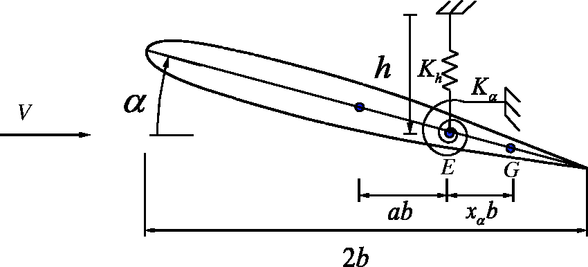
A typical two-dimensional aeroelastic airfoil system.
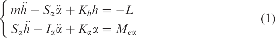
The governing equations of motion of such a 2-D system were derived from the Lagrange equations according to Dowell et al.,
16
written as
By introducing non-dimensional time
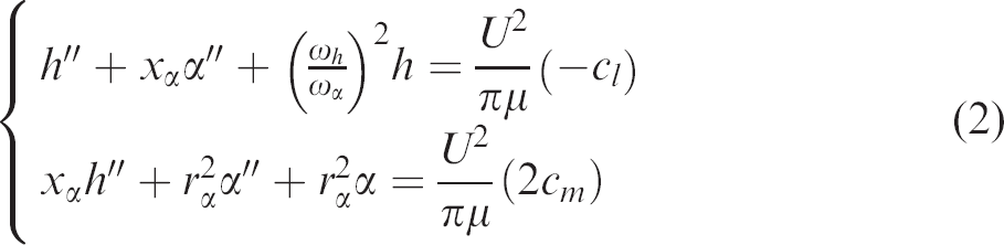
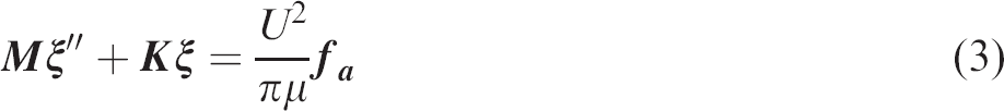
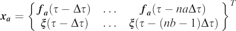
By defining the structural state vector
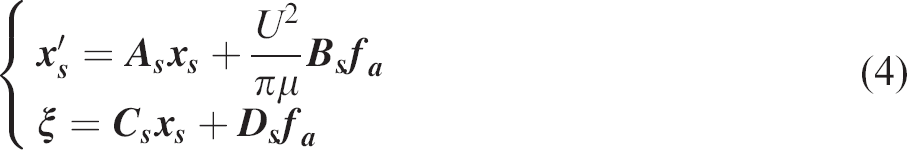
Aerodynamic ROM and flutter equation
Amongst the numerous methods, the system identification method is an effective and efficient technique to establish aerodynamic ROM. Following the suggestion from Cowan et al.
19
and Zhang and Ye,
22
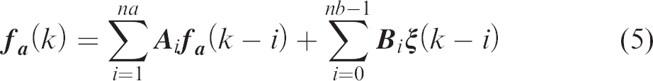
the ARX model is used to establish the ROM of transonic aerodynamics. The time domain equation for Multi Input and Multi Output (MIMO) ARX model can be described as
One advantage of ARX model is that the system response at any time step
In the present study, a so-called ‘3211’ signal developed by Cowan et al.
19
is utilized as the input of the CFD solve due to its broad frequency spectra. Then the least squares method is adopted to fit the time history of the output of the CFD solver, i.e.,
One challenging problem with using the ARX model to build aerodynamic ROM is how to determine the order of the model. In theory, the order of aerodynamic ROM could vary at different flow conditions, for instance, Mach number, angle of attack even airfoil profile. In the present study, identifying the model order is treated as a minimization problem at specific flow condition, which can be written in a general form
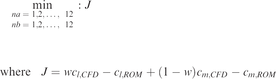
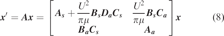
Thus, the Genetic Algorithm (GA) can be implemented to search the most appropriate order of ARX. And with well-determined orders and corresponding coefficient matrix, the discrete-time ARX model can be transformed into the continuous-time form through Tustin approximation, which can be described in state-space form as
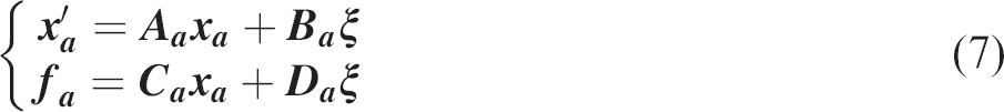
Then, introducing
Then, the critical non-dimensional flutter speed
The morphing wing mechanism
The original morphing technology was developed in the DARPA Smart Wing project. 25 , 26 A new morphing mechanism called Eccentric Beam Actuation Mechanism (EBAM) for both leading and trailing edges has been designed, analysed and tested in previous research 23 , 24 ,27–29 as shown in Figure 2(a). By rotating the EBAM at one end using an actuator, the wing shape is forced to deform depending on the EBAM rotation angle as illustrated in Figure 2(b) with the curvature of the chord line shown in Figure 2(c) to fulfill a specified morphing shape. The EBAM is connected to the skin through discs and stringers, which provide a pass-way to transfer the actuating force to the skin.
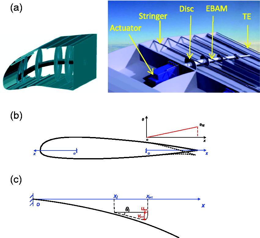
A morphing wing: (a) leading and trailing edge device, (b) airfoil shape, (c) deformed chord line.
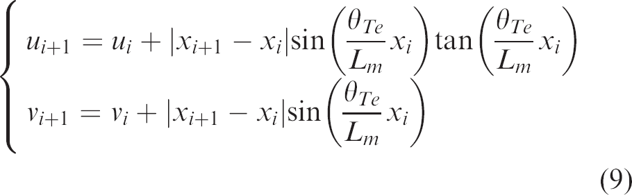
Taking the morphing trailing edge for example, the bending angle
Isogai wing model
ANSYS Fluent was used to model the aerodynamics based on the fluid governing equations, in which the Euler and Navier-Stokes equations were solved, respectively, by using the pressure-based coupled algorithm in the current paper. In Fluent, a control-volume-based technique is employed to convert the general scalar transport equation to an algebraic equation, which is solved by using a point implicit (Gauss-Seidel) linear equation solver in conjunction with an algebraic multigrid (AMG) method. To deal with viscous flow problems, a classical one-equation turbulence model, the S-A model, is used in current simulations. For spatial discretization, the second-order upwind scheme is implemented to interpolate the convection terms. In terms of temporal discretization, a technique called bounded second order implicit time integration is employed for real-time advancement.
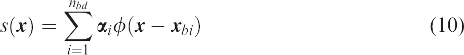
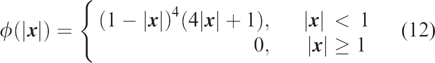
A Radial Basis Functions (RBF) interpolation for large mesh deformation
30
is implemented to enhance the capability of mesh deformation in ANSYS Fluent via user-defined function (UDF). The RBF interpolation

When the motion of nodes on the boundary, i.e.,

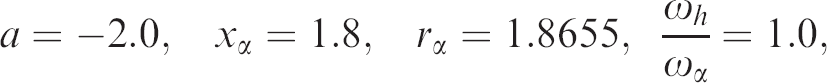
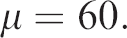
The Isogai Wing model is of NACA 64A010 airfoil with the following parameters
3
,
4
For a specified Mach number, ‘3211’ signal, as shown in Figure 3(a), is used as the inputs of CFD solver, and the corresponding coefficients of lift and moment can be obtained. Subsequently, the aerodynamic ROM is established for this Mach number. Typical time history of the aerodynamic coefficients at Mach 0.8 from CFD simulation and the aerodynamic ROM is shown in Figure 3(b).
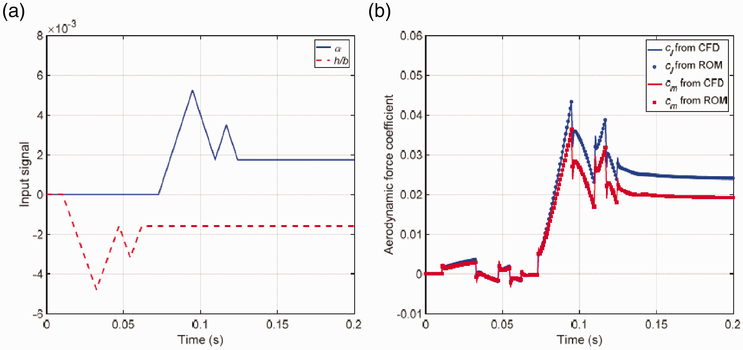
Comparison of aerodynamic force coefficient from CFD solver and ARX ROM for Isogai wing model at Mach 0.8 (Euler solution): (a) ‘3211’ signal, (b) lift and aerodynamic moment coefficients.
Based on the aerodynamic ROM, the root locus for different Mach numbers are used to determinate the critical flutter speed and flutter frequency. After depicting these results versus Mach numbers, the resulting flutter boundary in transonic regime is shown in Figure 4.
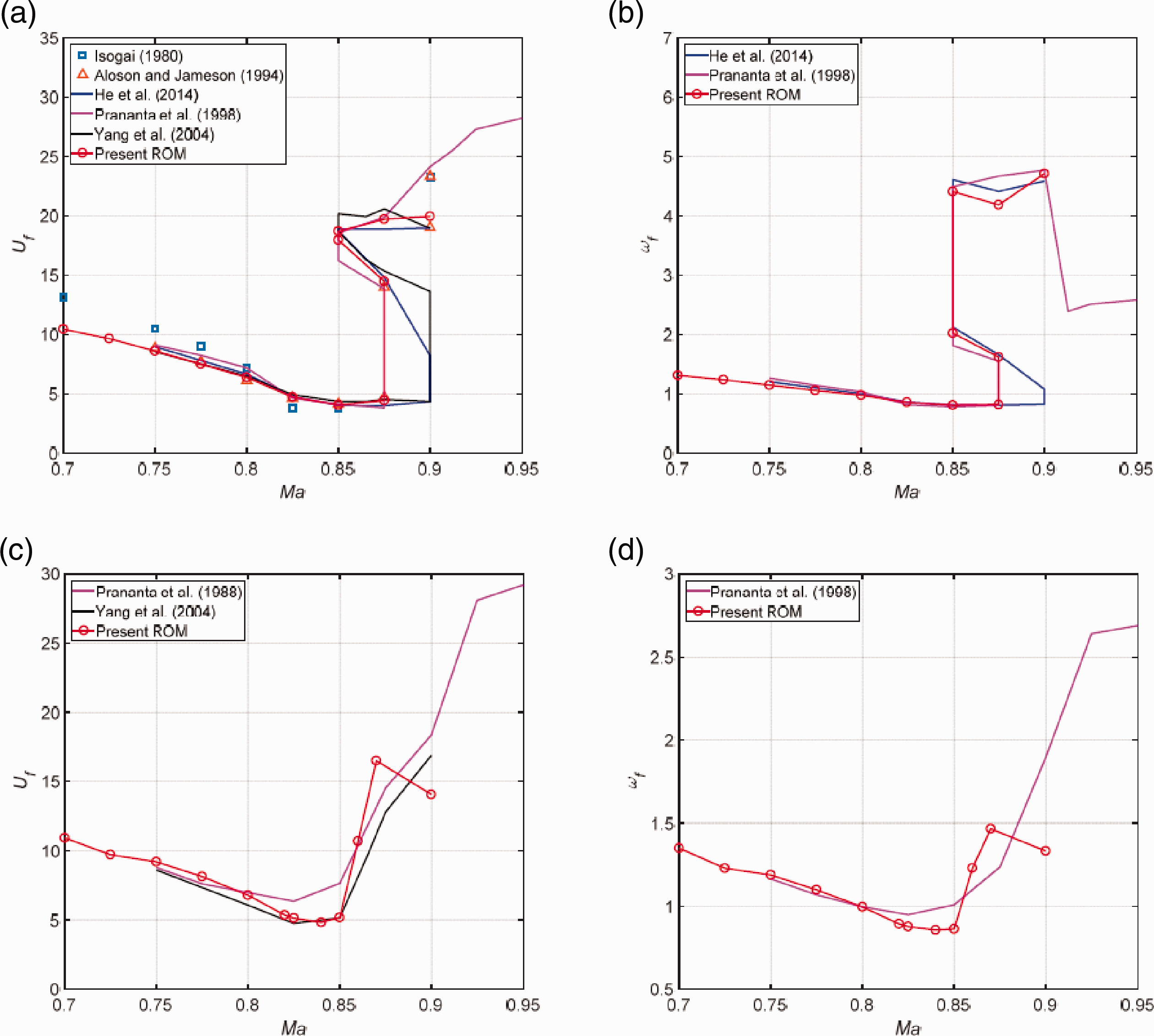
Comparison of flutter boundary of Isogai wing model: flutter speed (a) and flutter frequency (b) versus Mach number from inviscid solution; flutter speed (c) and flutter frequency (d) versus Mach number from viscous solution.
For the Euler solutions as shown in Figure 4(a) and (b), the results are in good agreement with those obtained by transonic flutter solution in the frequency domain 32 and time marching solutions. 17 , 33 , 34 The results show that the flutter speeds in transonic regime are lower than in the subsonic regime and there are multiple values of flutter speed occurring between Mach 0.85 and 0.9, which forms the so-called S shape flutter boundary. 35
Only a few studies of Isogai wing model in viscous flow are available in the existing literature. Aerodynamic ROM method are utilized to obtain the flutter solution at different Mach numbers as shown in Figure 4(c) and (d). Compared with the existing time marching solutions, 33 , 34 reasonably good agreements are achieved demonstrating the feasibility of the present methods. It is also found that the so-called S shape flutter boundary observed in the Euler computational results disappears for Navier-Stoke solutions.
Transonic flutter of a morphing wing
Flutter boundary of Isogai wing with morphing devices
The study was then extended to the Isogai wing model with morphing leading edge (LE) and trailing edge (TE) to investigate the transonic flutter characteristics. To focus on the effect of the aerodynamic profile variation of the morphing wing, the mass and stiffness distribution of the morphing wing keeps in the same values as the original Isogai wing.
The interface location of the LE and TE with the wing box is set at
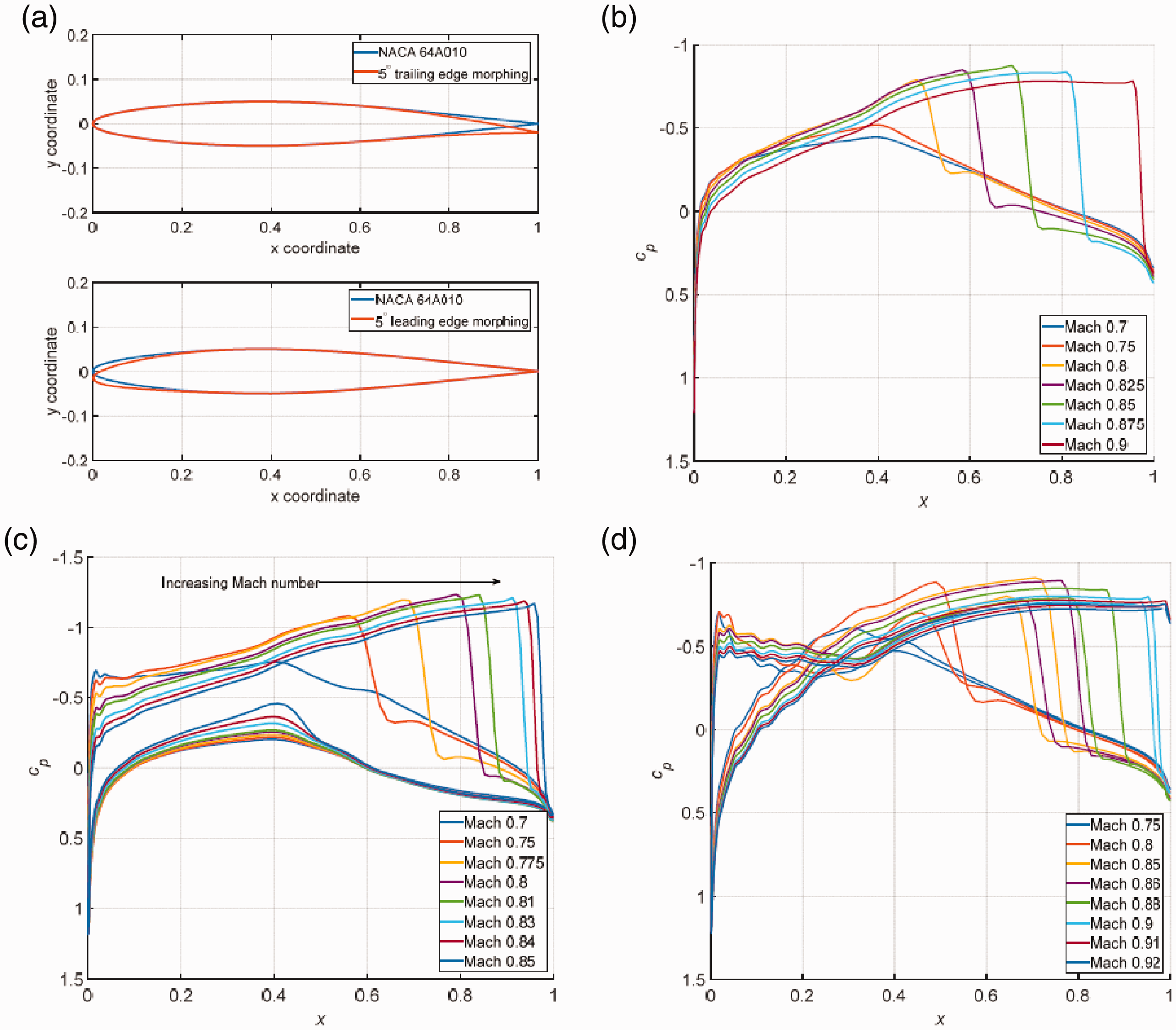
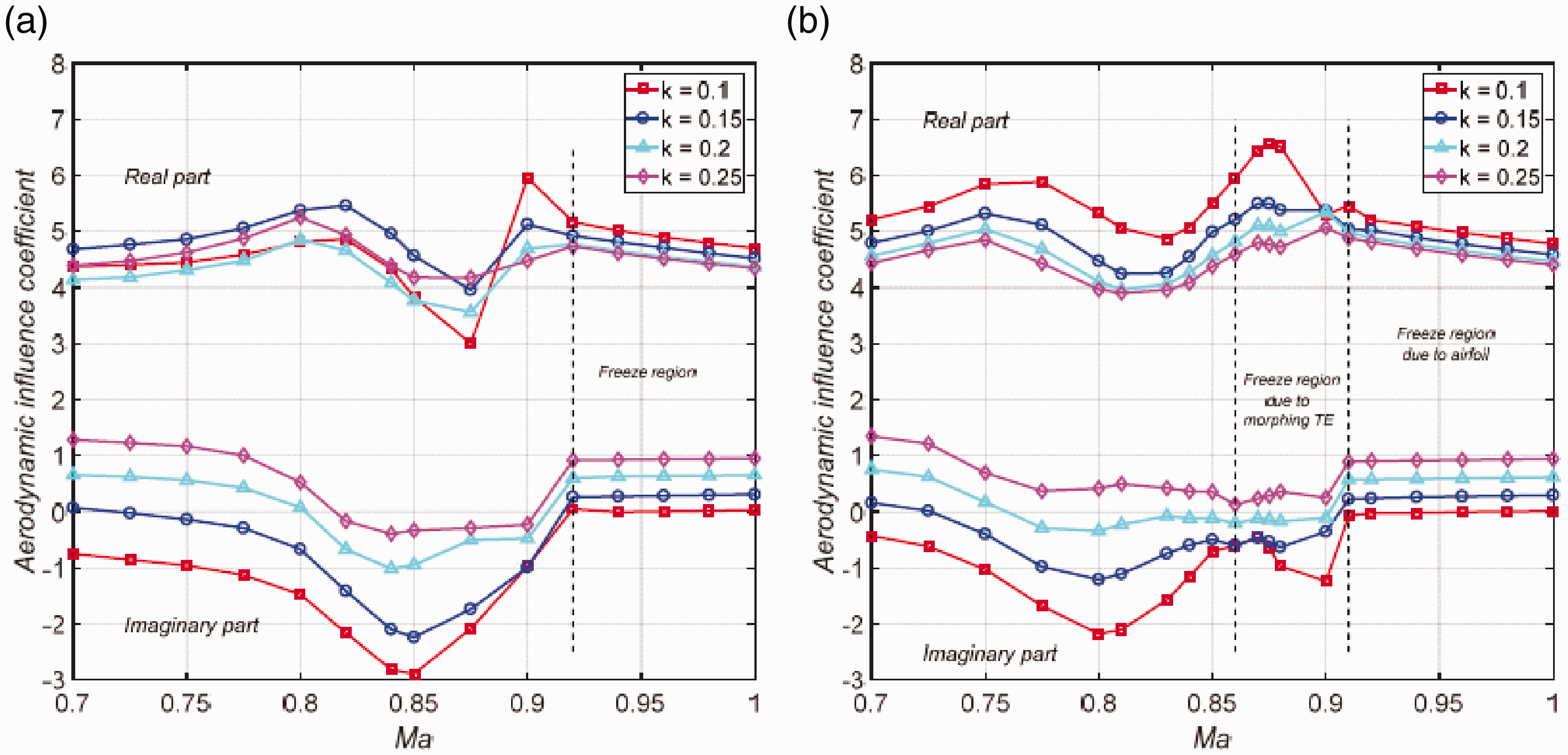
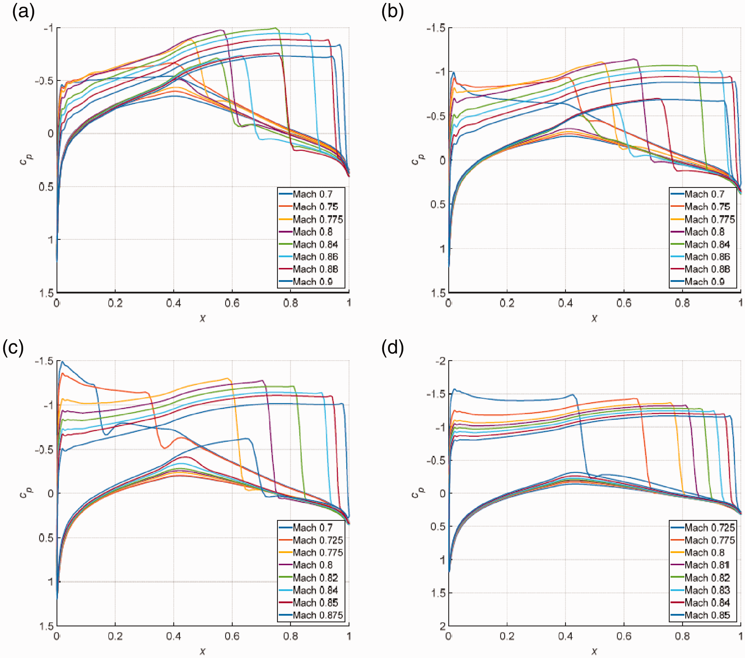
(a) Airfoil profile for morphing TE and LE and pressure distributions for (b) wing without morphing, (c) morphing TE
The effect of morphing TE and LE on the transonic characteristic of the wing can be considered via the aerodynamic ROM as well. By setting the morphing TE or LE at a specific deflection angle with zero mean angle of attack, the generalized aerodynamic forces due to ‘3211’ signal for the deformed airfoil shape can be obtained from CFD solver. The aerodynamic ROM can then be established at different Mach numbers. Subsequently, the process for searching the critical flutter condition over a range of flight speed was executed to determine the transonic flutter characteristics of the morphing wing.
Figure 6 shows the transonic flutter boundary of the wing with morphing LE and TE at different deflection angles based on Euler and Navier-Stokes equations. For the Euler results, for
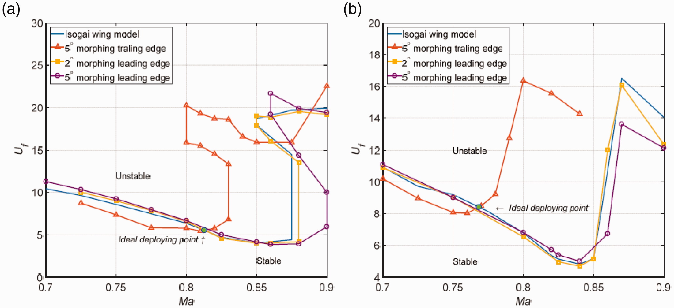
Comparison of flutter boundary of Isogai wing with the morphing wing based on: (a) Euler equation, (b) Navier-Stokes equations.
From Figure 6(a), it is apparent that the minimum non-dimensional flutter speed is about 5.45 for the morphing TE model with deflection angle of
Similar effects of morphing LE and TE on the flutter speed are observed for Navier-Stokes solutions as shown in Figure 6(b). Ideally, the minimum flutter speed in transonic regime can be increased from 4.82 of the original model to 8.41 with
From linear aerodynamics, 3 , 4 the flutter speed generally decreases in transonic regime below Mach 1, and increases significantly above Mach 1. The current results, as shown in Figure 6, present the same trend for both original and morphing wings. To the authors’ knowledge, the exact Mach number, in which the flutter speed starts to increase in the transonic regime, has not yet been fully understood. For that reason, it is difficult to give a general conclusion on flutter characteristics over transonic wings.
According Bendiksen, 36 , 37 the Mach number freeze phenomenon, or transonic stabilization law, plays an important role in the wing transonic flutter. Flutter speed may increase significantly when the freestream Mach number reaches the freeze Mach number. It is defined as the freestream Mach number at which shock waves on both upper and lower surfaces reach the TE of an airfoil. 36 , 37 And these phenomena have been also observed in our previous numerical cases. 38
In order to give physical-based explanations of morphing wing on transonic flutter, the relationship between the shock wave locations on airfoil surface, aerodynamic coefficient and the flutter characteristic is addressed.
To evaluate the unsteady characteristic of the transonic aerodynamics, the aerodynamic influence coefficient
20
is employed in the present study. The input of CFD, i.e. the pitching motion of the aeroelastic airfoil, is taken as a sinusoid function

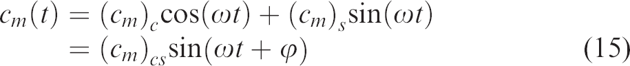
As for the coefficients
Then the aerodynamic influence coefficient of different reduced frequencies (
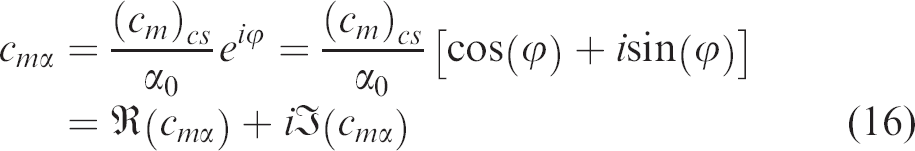
Aerodynamic influence coefficient due to pitching oscillation around
From Figure 5(b), according to the Euler solution, it can be observed that the freeze Mach number is around 0.9 for the original NACA 64A010 airfoil according to the location of shock wave. When Mach number is greater than freeze Mach number, the unsteady aerodynamic moment coefficient become stable as clearly observed in Figure 7(a). Meanwhile, a strong stabilization of the flutter boundary occurs as shown in Figure 6(a), which coincides with the observation in Ref. 36.
Following the Mach number freeze phenomenon for the undeformed airfoil, the shock wave for the morphed airfoil with a TE deflection
In summary, a possible explanation in improving the transonic flutter characteristic is that employing the morphing TE makes shock wave and Mach number freeze region occur at an early Mach number.
Appearance of shock wave and transonic flutter characteristic
From previous results, it can be seen that the shock wave location plays a vital role in the transonic flutter characteristics. A more general approach to alter the appearance of a shock wave is to vary the angle of attack (AoA) of the airfoil. To study the effect of morphing devices on the transonic flutter characteristics, the analysis was conducted at different AoA in this section. Special attention was paid to the relationship of the appearance of the strong shock wave on the upper surface of the airfoil and the transonic flutter boundary. It should be noted that Euler equations are applied in this section.
Similar to a morphing wing, the AoA effect on the wing transonic characteristic can be considered via the establishment of aerodynamic ROMs. The AoA of the Isogai wing model was set to a specific value in CFD solver when calculating aerodynamic coefficients due to ‘3211’ signals. Then the wing transonic flutter characteristics at this AoA was obtained by eigenvalue analysis.
Since Euler equations are adopted, the AoA is restricted to a small range from
Pressure distribution across transonic region at angle of attack of (a)
Figure 9 shows the flutter boundary of the original Isogai wing model at different AoAs. It is noted that the bottom of the flutter boundary moves up as AoA increases. For small AoAs between

Flutter boundary of Isogai wing model at different angle of attack.
Yates et al. 39 also noted that the growth of the supersonic area on the wing surface causes the aerodynamic center of the wing move backward, and the flutter speed increases with the AoA. Moreover, the numerical simulation by Edwards et al. 40 indicates that the flutter speed rises when the shock wave forms on the upper surface. The results obtained in the current study are consistent with the above observations.
Another approach to evaluating the effect of the shock wave on the flutter boundary can be made by altering the AoA at the same Mach number. As the AoA increases at Mach 0.8, the flutter speed decreases slightly at small AoAs and then recovers, as shown in Figure 10(a). When the AoA is larger than 2°, a strong shock wave emerges on the upper surface as shown in Figure 10(b). Meanwhile, the downwards trend of flutter speed stops and starts to grow gradually.
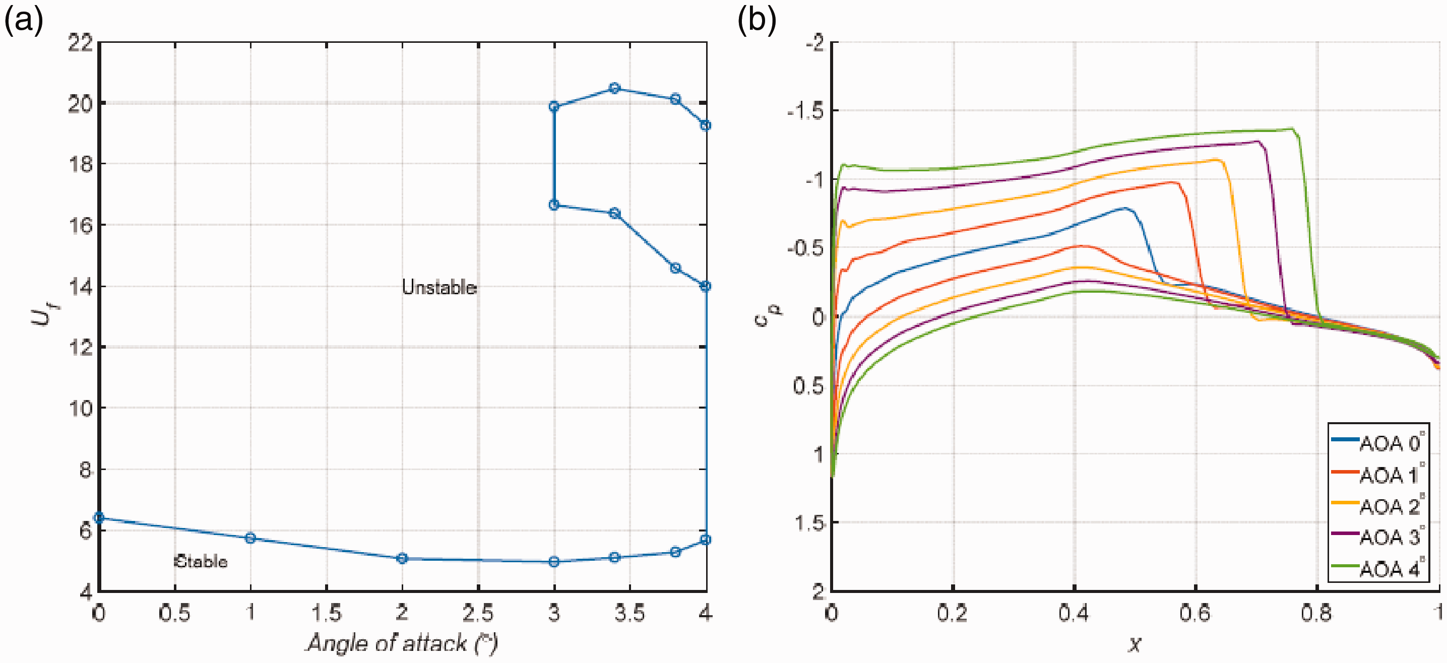
Effect of AoA on the flutter speed for Isogai wing model at Mach number 0.8: (a) The flutter speed at different AoA, (b) Steady pressure coefficient distribution at different AoA.
As shown in Figure 11, the scenario at Mach 0.84 is slightly different from Mach 0.8 when a strong shock wave has already been established at AoA=
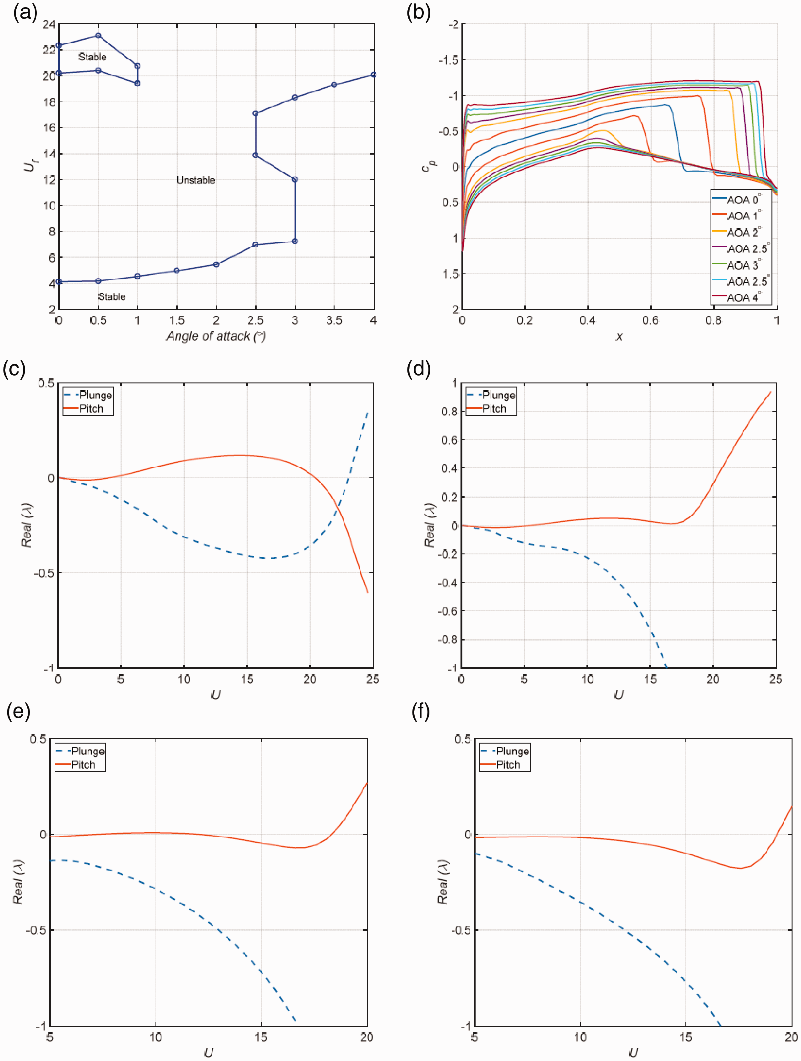
Effect of AoA on the Isogai wing flutter speed at Mach number 0.84: (a) flutter speed at different AoA, (b) steady pressure coefficient distribution at different AoA, real part of aeroelastic eigenvalue versus non-dimensional air speed at (c) AoA =
It is noted that the flutter boundary varied with the AoA and formed an S shape as shown in Figures 10(a) and 11(a). This was also observed from the conventional flutter boundary corresponding to Mach number in Isogai wing model section. When the AoA is increased at a fixed Mach number, the flow velocity on the upper surface of the airfoil is accelerated. A similar effect on the flow field exists by increasing the Mach number at a fixed AoA. When the AoA is between
In summary, the above results reveal that by varying Mach number, AoA or morphing TE deflection angle, the appearance of a strong shock wave on the upper surface of the airfoil leads to a reverse of the downward trend of flutter speed. When the shock wave on the upper surface reaches to the TE, the flutter speed starts to increase significantly. Thus, the mechanism of improving the transonic flutter characteristics by morphing TE is due to the shock wave emerging and moving to the TE at an early stage with lower Mach number. It is also note that the morphing LE has negligible effect on the shock wave and the flutter boundary in the transonic dip region.
Time domain transonic flutter analysis of a morphing wing
Due to the fact that morphing change requires a period of time to be implemented in structure, the aerodynamic configuration is being altered during this process, which may lead to unexpected influences on the aeroelastic behavior. For that reason, a time domain analysis considering TE morphing process is performed to assess these effects, which is conducted by the time marching method based on CFD.
In the following simulations, the morphing in the TE starts at
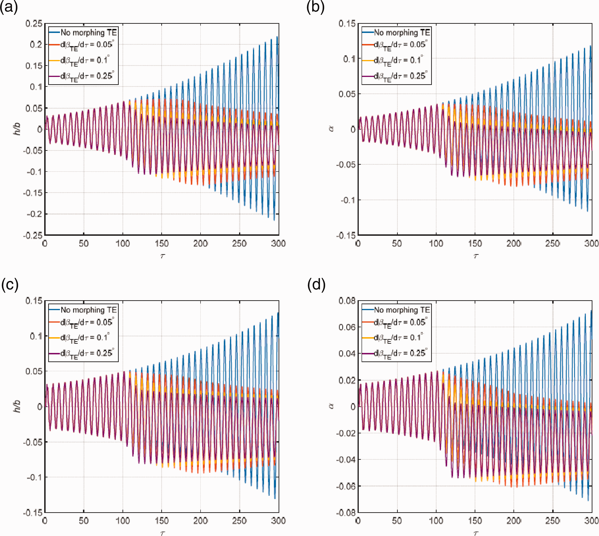
Aeroelastic response of morphing wing with different morphing speeds: (a) plunging motion and (b) pitching motion at U = 4.5 of Mach 0.85, (c) plunging motion and (d) pitching motion at U = 4.6 of Mach 0.875. (
Also observed in Figure 12, the static aeroelastic deflections of pitching and plunging motions converge to non-zero positions when the TE morphing is deployed. In particular, a negative mean AoA occurs because of the negative pitching aerodynamic moment induced by employing the morphing TE. From previous section, it is known that the AoA can influence the flutter characteristic of the aeroelastic system. Thus, the flutter speed obtained from the time marching method in this section is a result of both mean AoA and morphing TE. Note the results in this section are different from Figure 6 where only deformed shape is considered and zero mean AoA is assumed.
The flutter speed boundary obtained by time marching approach is displayed in Figure 13, and the flutter speeds for the original Isogai wing and morphing wing with constant mean AoA are presented. It is observed that the minimum flutter speed of flutter boundary is improved by 16.8% to 4.72 with respect to the original Isogai wing. During the current analysis, it was noted that the mean AoA induced by morphing TE is about
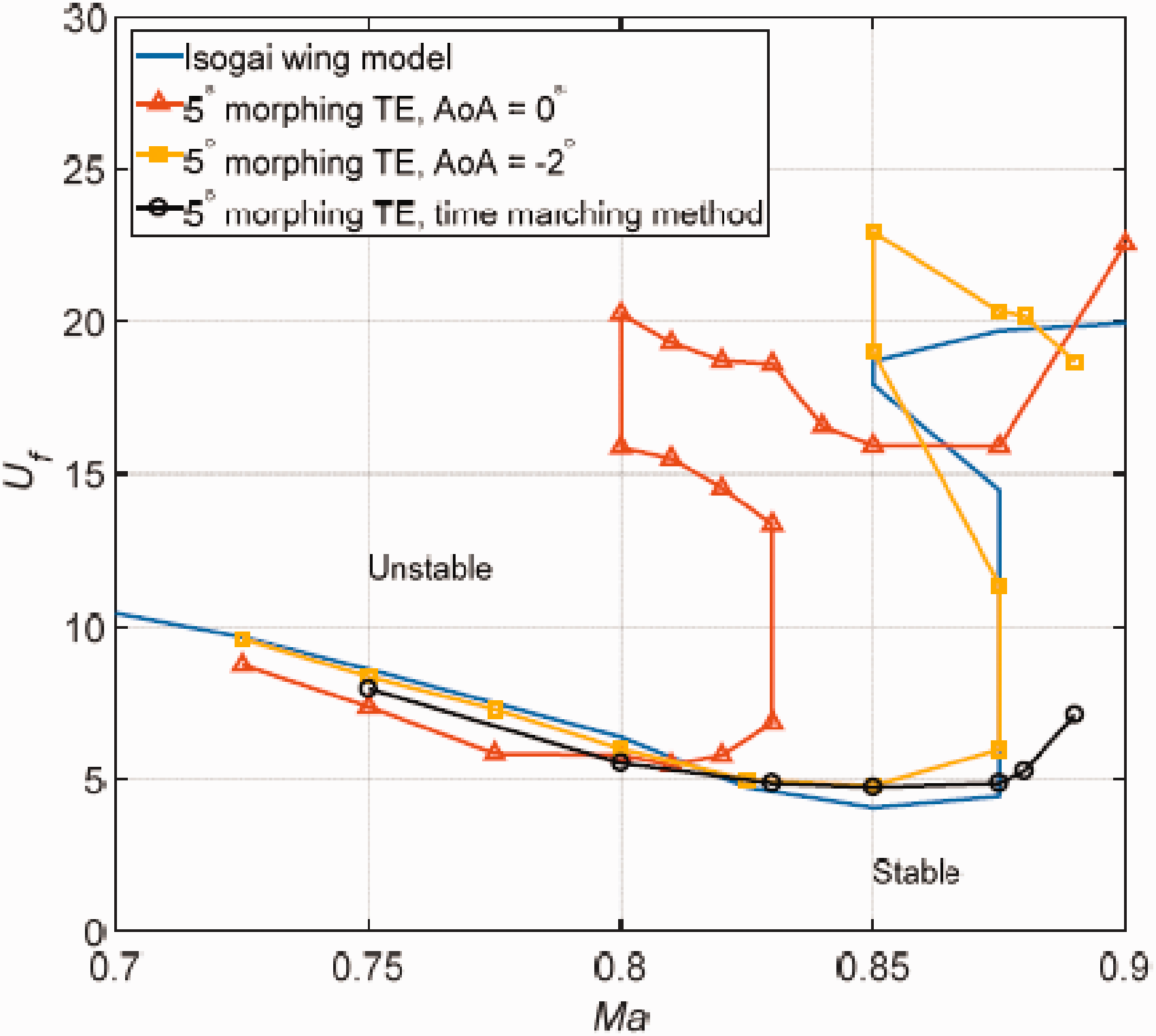
Flutter boundary of Isogai wing with the morphing trailing edge from time marching method.
Conclusion
The transonic flutter characteristic of a 2D airfoil system with morphing trailing and leading edges is studied. The Fluent software based on Euler and Navier-Stokes equations is employed with an RBF interpolation model to improve the capability of mesh deformation in the CFD model via UDF. An ARX model is implemented to establish aerodynamic ROM with the GA used to identify the model order. The critical flutter speed and frequency can be obtained by solving the eigenvalue equations at specific flow conditions. The flutter boundary can be subsequently obtained with a type of S shape flutter characteristic corresponding to AoA and Mach number for Euler solutions.
The relationship between shock wave locations on transonic flutter characteristics for the present model shows that the transonic flutter boundary depends on the forming and location of the shock wave on the upper surface of the airfoil. Corresponding to Mach number, the flutter speed will revise the downward trend and increase significantly following a strong shock wave taking place and moving close to the TE.
It is observed that the morphing TE provides an effective way to improve the transonic characteristics. For the presente wing model, the morphing TE leads to an increase of the transonic flutter speed by 36.9% based on Euler equation or 74.5% based on Navier-Stokes equation. The study reveals the a possible mechanism of the improvement of transonic flutter characteristics of morphing wing is that it makes shock wave and Mach number freeze region occur at a lower Mach number. However, the morphing LE has negligible effect on the transonic flutter characteristics because of its weak influence to the shock wave taking place near the TE.
Time domain analysis show that that the morphing speed has negligible influence on the stability of aerodynamic airfoil, and the minimum flutter speed of flutter boundary is improved by 16.8% with respect to the original wing. The effective Mach region for employing morphing TE to improve transonic flutter characteristic narrows, which is caused by the change of mean AoA.
Footnotes
Declaration of conflicting interests
The author(s) declared no potential conflicts of interest with respect to the research, authorship, and/or publication of this article.
Funding
The author(s) disclosed receipt of the following financial support for the research, authorship, and/or publication of this article: This work is supported by the National Natural Science Foundation of China (Grant 11972079) and Innovate UK.