
Abstract
Bonding is known for its wide range of advantages over bolted joints when joining different materials together. However, the advantages e.g. of homogeneous load distribution can quickly be lost in case of overload. For this reason, the load occurring in the adhesive is reduced by constructive measures far below the yield stress of the adhesive, which leads to a conservative joint design. And to be on the safe side, a few “chicken rivets” are then placed again. This problem is particularly well known in aviation. Highly loaded components are structurally bonded by a combination of rivets and adhesive in order to underline the advantages of structural adhesive bonding with the safety of the well-known bolted joints. Known as fail-safe design, this concept is damage tolerant and more robust against manufacturing defects through a secured double load path.
Especially when joining fiber-reinforced composites, bolts weaken the adherends of the joint and only contribute to load transfer when the brittle adhesive fails. With the help of Surface Toughening, a boltless technique for reducing stress concentrations and arresting cracks in adhesive bonded joints is available. This work describes the industrial application of this technique. Starting with coupon tests and a small scale demonstrator to ensure the compatibility with industrial manufacturing processes, such as infusion and prepreg manufacturing, a large scale demonstrator of a 2 m carbon fiber reinforced plastic (CFRP) - HTP leading edge with hybrid laminar flow control is manufactured by the industrial partner AERnnova. Verifying a simple and cost-effective application of the technology, Surface Toughening enables robust bonded joints with a minimum impact on today's process of adhesive bonding.
Introduction
In this paper Surface Toughening, an effective and simple concept for increasing joint strength, is used to solve a strength problem of bonding a hybrid laminar flow control (HLFC) leading edge. Surface Toughening also has an additional crack stopping capability, which makes the entire bonded joint much more robust. Starting with coupon tests, the application will first be validated in a small scale demonstrator using the infusion method and then transferred by Aernnova to a 2 m demonstrator.
Project background
In the European Union (EU) project Clean Sky 2 - Large Passenger Aircraft Platform 1 – HLFC on HTP, the German Aerospace Center (DLR) develops in cooperation with Aernnova a hybrid laminar flow control (HLFC) leading edge demonstrator for the usage on a horizontal tail plane (HTP) of an Airbus A350. A HLFC-structure extracts the turbulent boundary layer of the airfoil through a perforated skin by negative pressure and decreases thereby the aerodynamic friction drag.1–3 Airbus made the first experiences with laminar flow control with a modified HLFC vertical tail plane in flight test in the late 1990s with an Airbus A320. 4 The DLR followed on from the EU project Application of hybrid Laminar Technology to Transport Aircraft (ALTTA) funded in 2000-2003 and reduced the complexity of systems and increased the efficiency. 5 The design in this project consists of an outer micro perforated Titanium skin and an inner carbon fiber reinforced plastic (CFRP)-sub structure which builds the load carrying part. This substructure is equipped with chambers for leading the air to the vacuum pumps. Figure 1 shows the design model of the HLFC leading edge. Next to the manufacturing of a perforated skin and the substructure, which is important for handling the external loads and transfers them to the front spar, the joining of both components is a challenge. Classical bolting is not possible due to strict aerodynamic requirements to the smooth surface. A larger distortion on surface like a rivet head leads to transition and increase the aerodynamic drag. 6 Therefore, adhesive bonding is used to join the hybrid material structure as shown in Figure 1.
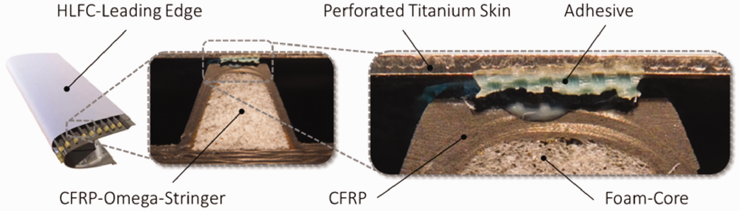
Bonding of a HLFC-leading edge structure.
Because of the hybrid material design and as result the different thermal expansion coefficients, and the usage of an elevated temperature curing adhesive, the bonding process is of great importance due to the induced stresses of temperature change. At the beginning of the project, a “one-shot” manufacturing process was aimed at, in which the titanium skin is co-bonded using the RTM6 infusion process at 180 °C. Difficulties with the quality of the bonded joint were identified after cool down. As a result edge near areas were debonded. On the basis of finite element analysis (FEA), it was shown that the strength of the adhesive was exceeded. A so called “secondary bonding” was preferred and allowed a reduction of curing temperature of the adhesive from 180 °C to 120 °C. The deformation and resulting shear stress in bondline is shown in Figure 2. By the usage of the “secondary bonding”, a separate selective heating only of the bonded area reduced deformation and bondline stress additionally. However, high stress concentrations remained in the adhesive.
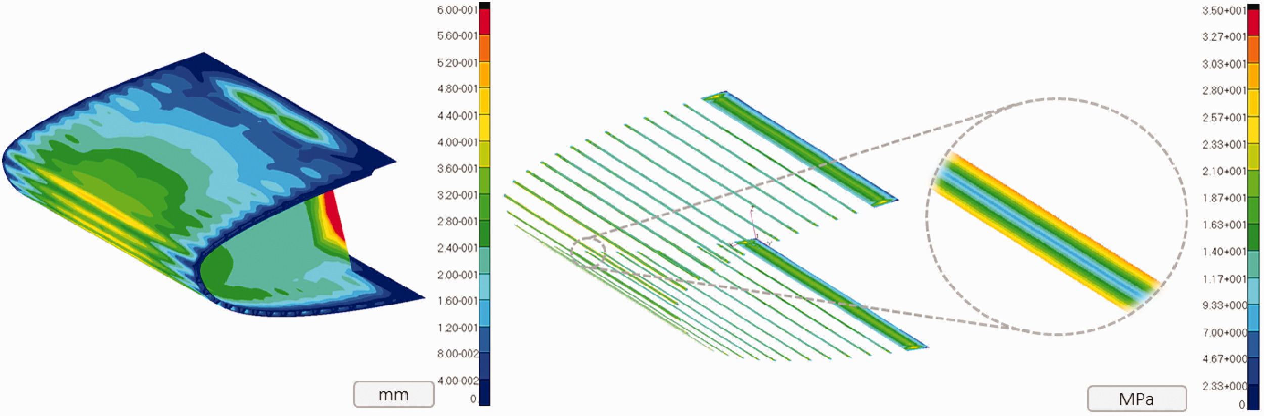
Left side shows the deformation of structure after cool down to 23 °C from the adhesive curing of secondary curing only of the bonded areas of 120 °C. Structure is fixed on the free edges. Right side shows the resulting shear stress of the bondline between CFRP-structure and perforated titanium skin. Stress concentrations on the edges of the bond.
The 800 mm long model is a mixed shell and solid element model with solids for the bondline and the foam core and shells for the laminates, the titanium skin and the ribs. Mashed with iso mesh Quad4 elements for shell and Hex8 elements for the solids, the elements length is 2.6 mm. Over the bondline thickness are 5 elements placed. The material properties are linear elastic and the boundary conditions were fixed to the outer edges of the model to simulate the mounted condition on HTP. The simulations were verified by a lot of small manufacturing demonstrators. Figure 3 shows a comparison of FEA and 3 D-measuring by Gesellschaft für Optische Messtechnik GmbH (GOM) ATOS. It can be seen that the deformations of the asymmetric demonstrator are well reproduced by the FEA. It can also be seen that the problem of different coefficients of thermal expansion has a large influence on the deformation of the structure.
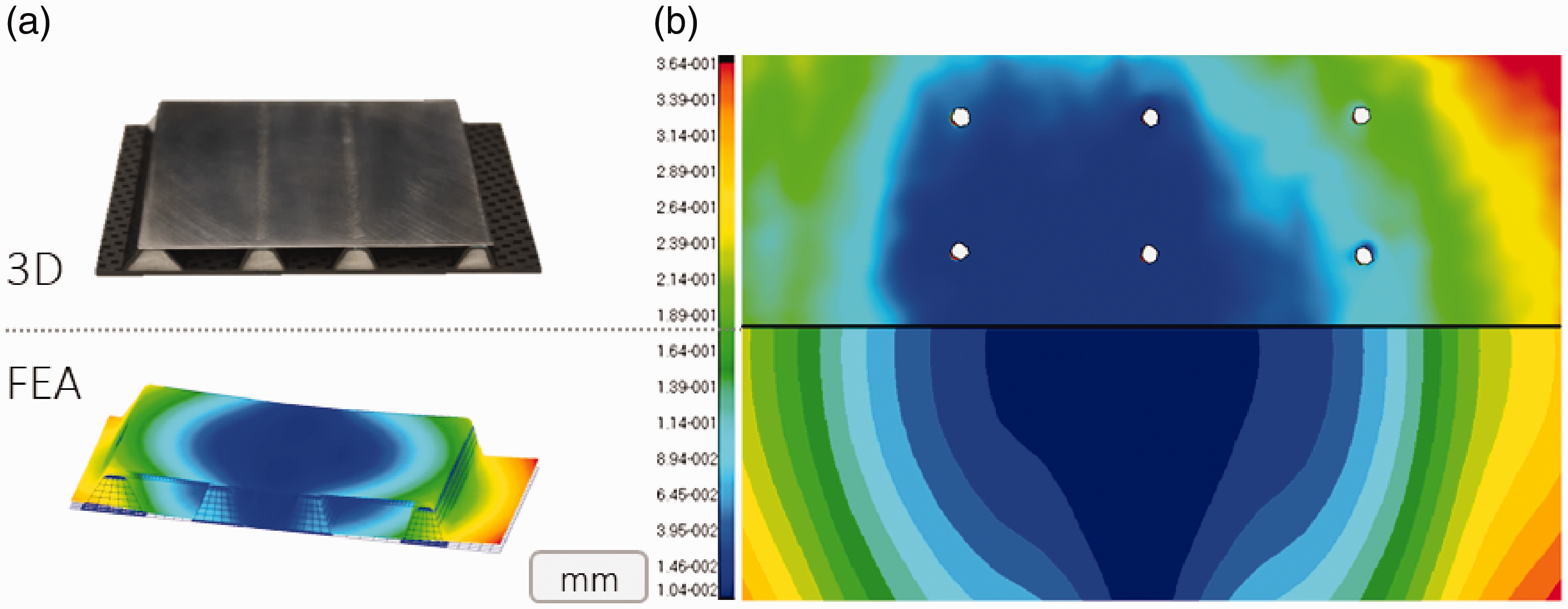
(a) Small scale manufacturing demonstrator and the FEA model. (b) The deformation of the bottom side of the demonstrator/FEA from left side is shown.
In analogy, the bondline is loaded nearly the same as a single lap joint under tension. There, the classical stress distribution along the bondline with peaks at the edges of the bonding as known from Volkersen 7 and Goland and Reissner 8 for shear and peel stresses are present. As a result, an increased risk for failure exists. Probably, a fatigue failure damages the bondline in operation. The chambers debond from the skin and the sealing of the chambers is therefore lost. The function is drastically decreased and the business case is lost. To reduce the risk of failure, a simple increase of overlap area is not possible. Aerodynamic requirements forbid an increase of blocking area of suction by an enlargement of the bonding area.
State of the art
Many concepts for increasing the strength of joints are known from the state of the art. These include, for example, chamfering, bi-adhesive usage, graded adhesives, spew fillets, pinning and adhesive modifications by nanoparticles. Shang et al. 9 collected all known concepts for increasing the joint strength and compared them to each other very well. Schollerer et al. 2 concentrated on the concepts to be applied in industry and compared the stress reducing effect by FEA and compared the joint strength of SLJ of different spew fillets, 45° chamfering and a local thermoplastic toughening concept. The results with an overlap length of 25 mm with Hysol® EA 9695 0.05 NW AERO film adhesive and a Hexcel® 8552 IM7 quasi isotopic laminate with 65 GPa modulus of elasticity showed very little impact in strength with the spew fillets (3% increase with a half triangle geometry and 1% decrease of strength with an arc geometry), an 8% increase with chamfering, while the new local surface toughing with a 0.125 mm Kynar® 740 Polyvinylidenfluorid (PVDF), applied 5 mm into the surface of the overlap edge, showed a strength increase of 84%. A complete modification of the surface, however, only leads to an increase of 6%.
Surface toughening
All known concepts from the literature to reduce stress concentrations and therefore increase the joint strength cannot be used in this issue. Chamfering is geometrically not possible, pinning is not allowed due to the named aerodynamic surface requirements of the forward step, creating a specific spew fillet is not a bussines case due to the great effort of the bonding mold, especially when film adhesive is used. This also applies to the targeted use of bi adhesives, which are very difficult to dose in industrial applications and aditionally are hardly possible to use with film adhesives. However, a further development of the Hybrid Bondline 10 investigated by T. Löbel seems to be a promising solution for this problem. This further development is called Surface Toughening.
As the name implies, the concept is based on a local toughening of the adherend’s surface near the overlap edges as shown in Figure 4. If the bonded joint is loaded, the ductile material at the edge of the bond compensates the stress concentrations. The joint is loaded more equally. In Shang et al. 11 is also investigating a surface toughening concept using an elastic GFRP layer on a stiff CFRP adherend and is demonstrating this effect as well. In his work, the increase of joint strength is about 22% for full surface toughening of the overlapped area.
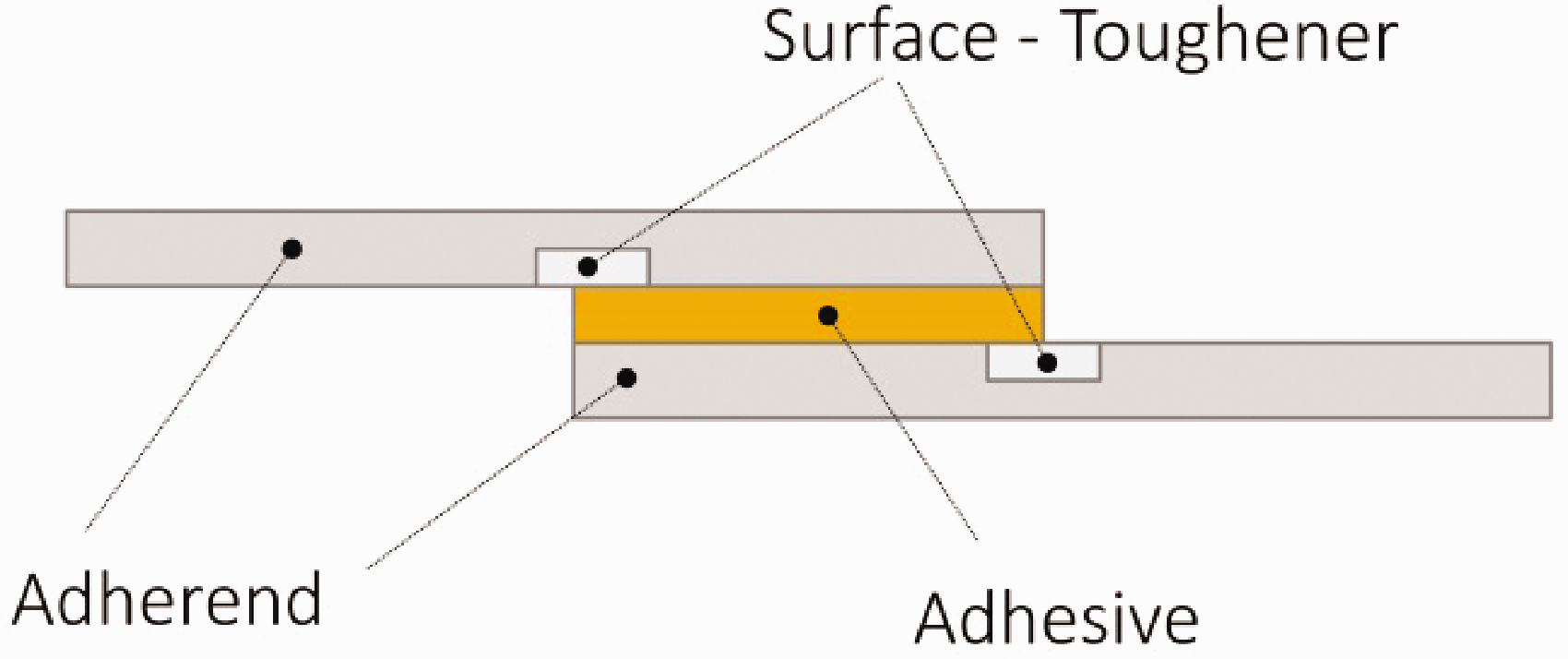
Surface Toughening, stress peak reducing concept.
Joint strength increase
Surface Toughening (ST) 2 was investigated and proofed to increase in joint strength. The Surface Toughening concept was explained and compared by FEA to the industrial usable state of the art concepts to increase the joint strength for SLJ. Accompanied by digital image correlation (DIC), Kosmann describes in Kosmann et al.12,13 the specimens strain is made visible and quantified. Also a crosscheck about strain and stress peaks of FEA and tests were done. The results show an increase of joint strength up to 84% for Surface Toughening. The benefit is on the one hand an increase of joint strength while on the other hand a very simple manufacturing process is realized. In other state of the art concepts the bondline or adherend must be modified mechanically, in the Surface Toughening concept, the adhesive cures regularly and the adherend needs no attention. In CFRP the ST-material is placed and co-cured on the laminate. The concept is derived from the work of Löbel, 10 where a crack arresting concept for adhesive bonding is investigated by a mix of adhesive bonding and thermoplastic welding.
Crack arrest
As known from SLJ’s specimens, stress concentrations occur at free adhesive edges which initiate a crack growth if the actual energy release rate is higher than the critical energy release rate of the material. This crack propagates without restriction in adhesive layers. As shown in Figure 5, for example, a crack is demonstrated at 100,000 cycles and 500,000 cycles. In the reference sample the crack grows unhindered, while in the ST specimens the crack stops growing in front of the ductile material. The high stress concentrations that occur at the crack tip are decreased and homogenized by the ductile material. The crack therefore does not grow any further through the bondline. In addition, the stress concentrations must not be higher than the tolerable stresses of the crack stopper.
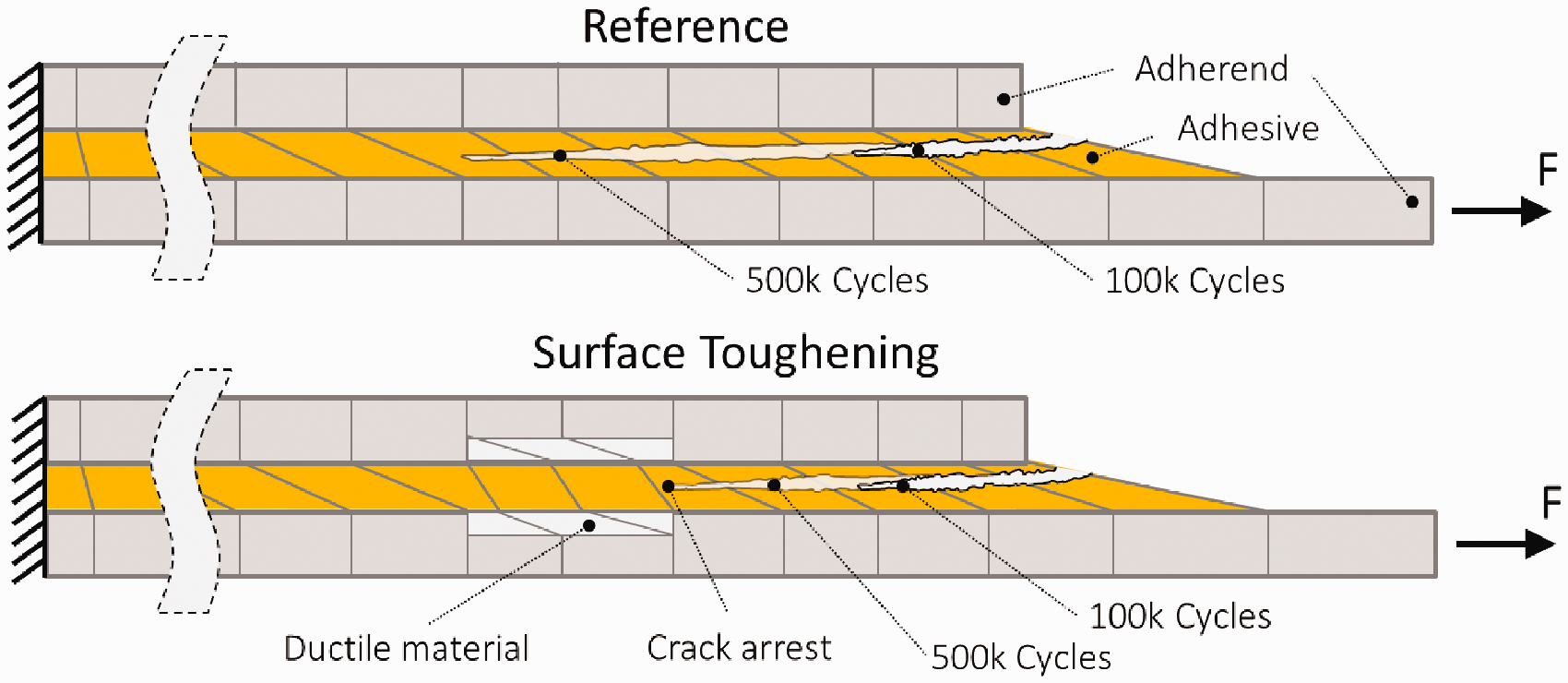
Functional principle as a crack arrest concept in cracked lap shear specimen.
Further, cracked lap shear (CLS) specimens were manufactured and dynamically tested to investigate the surface toughening capability for crack arrest. As shown in Figure 6, specimens are bonded and tested once without PVDF as the reference and with PVDF as the Surface Toughening. The stacking of CFRP, the adhesive, the PVDF and the manufacturing of the specimens is identical with the detailed description from Schollerer et al. 2 The length lST is set to 10 mm with a thickness of tST = 0.1 mm. The width of specimen is 25.4 mm.
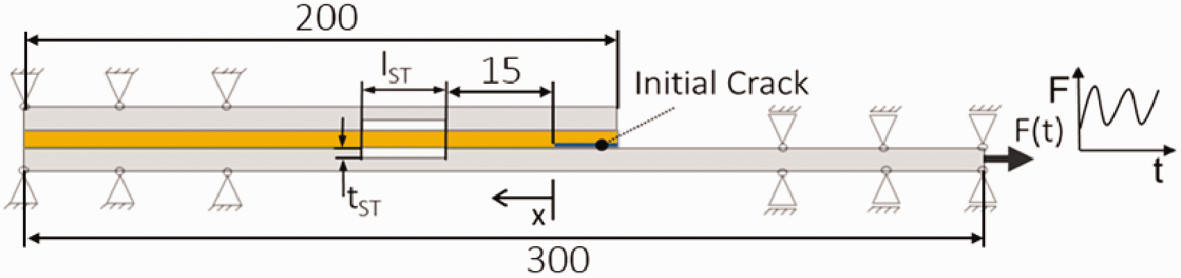
Geometry of CLS specimen to prove a crack arrest capability of surface toughening.
Geometry of CLS specimen to prove a crack arrest capability of surface toughening.
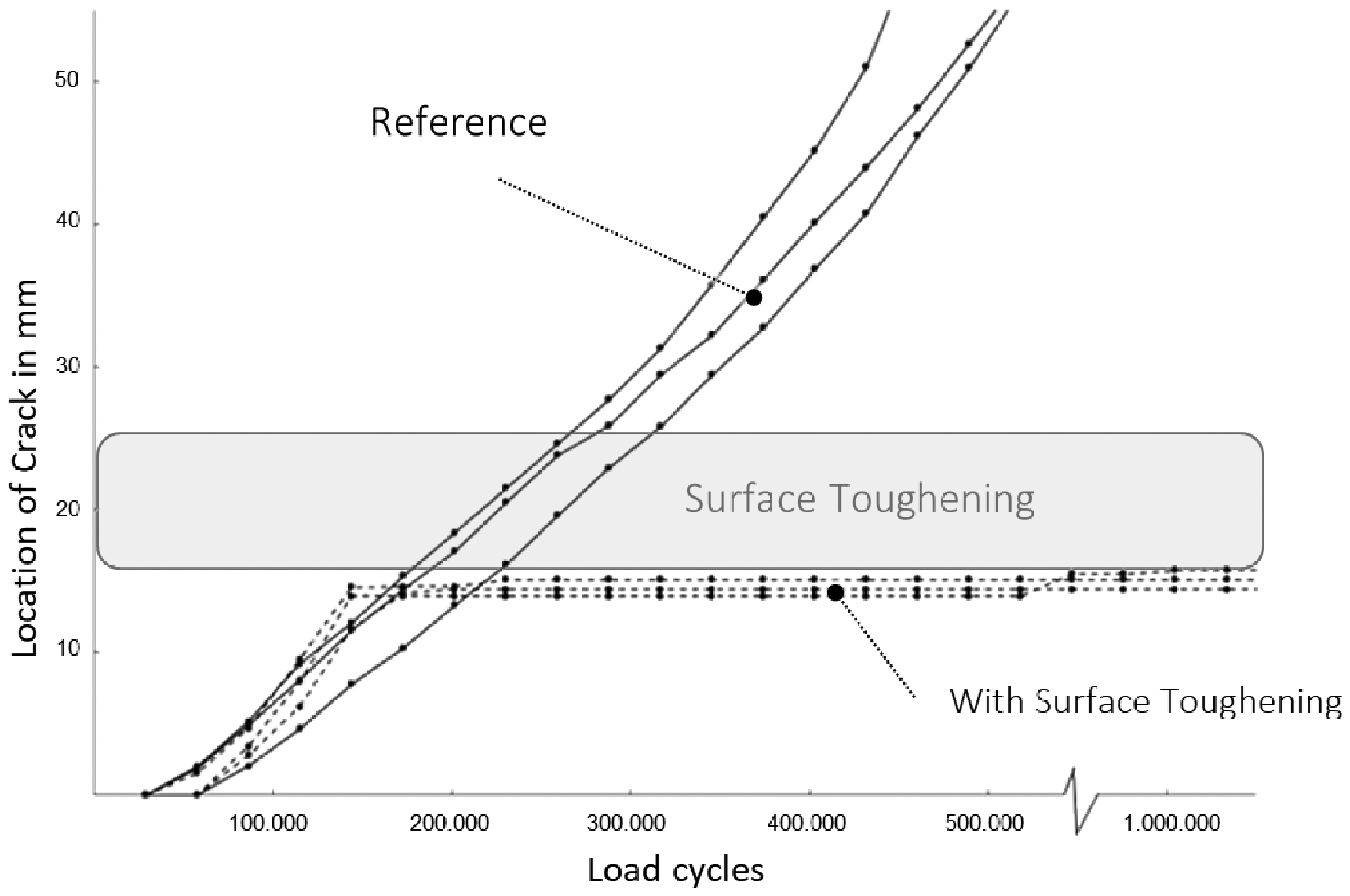
Since the test program is still running, only the specimens with a load of 3000 µm/m (F = 9.28 kN with a frequency of 8 Hz) are presented.
At a maximum strain of 3000 µm/m, cracks can safely be stopped in the bondline as seen from Figure 7. The crack stops in some cases 1 mm before the ductile material begins. In this investigation only the crack stop capability was experimentally tested. In a further investigation, the whole study will be presented and discussed in detail.
Application on element level
To verify the application to the HLFC structure, the investigations at coupon level are extended to element level tests. A small scale demonstrator is manufactured and observed under different temperature ranges. The aim is to ensure that the ductile thermoplastic material (PVDF) performs its function even at low temperatures. The investigated temperature range that could be generated was from –20°C to 120 °C.
Stress investigation
As named, PVDF is a good material for tough modification of the joining partner and is used in the demonstrator. A FEA model of a flat demonstrator with the dimensions of 130 x 180 mm is simulated with the cooling process after bonding. Therefore a combined shell and solid model is created again with MSC Patran and solved with Nastran. Thereby 3 elements are chosen over the bondline thickness and an element distance of 0.2 mm for the length and width. The whole model is only fixed at one node to allow a free deformation. The load on the bondline is caused by the final cooling to 23 °C RT of the entire structure after curing of the adhesive at 120 °C (curing temperature of FM94). The different deformations are transferred by stresses in the adhesive. Again, the classical stress concentrations occur at the edges of the bondline. These are significantly reduced by Surface Toughening, as shown in Figure 8. In terms of calculation, the stresses of the bond are reduced significantly below the limit set for the failure of the adhesive to occur.
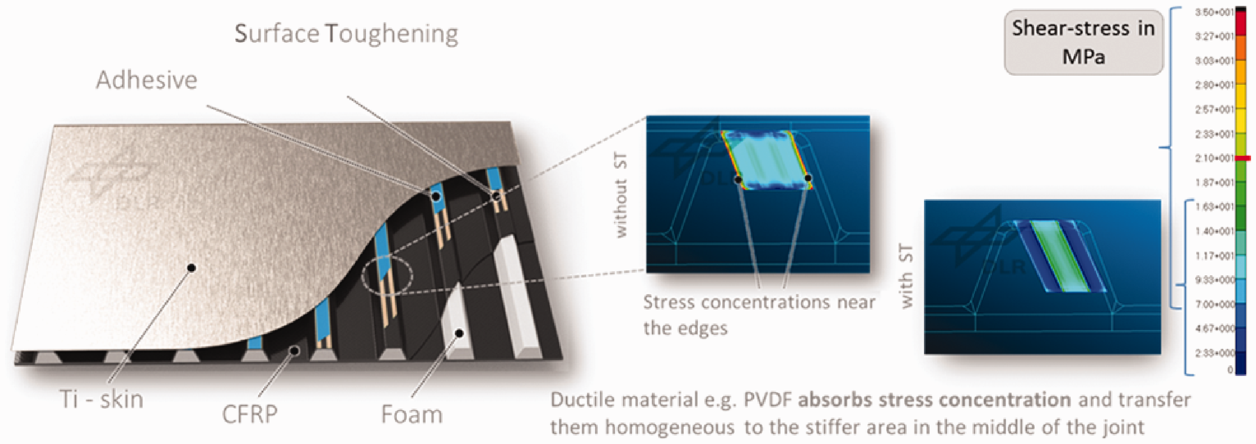
Implementation of surface toughening in the HLFC – LE structure with the qualitative stress levels of Bondline.
The result of the FEA investigations is that a 3 mm strip at each of the edges of the adhesive layer reduces the stresses to the required level.
Manufacturing
In this case, the infusion process with G0926 fiber and HexFlow® RTM6 resin from Hexcel is used for manufacturing. The Kynar® 740 PVDF foil is computerized numerical control (CNC)-cutted and sandblasted to increase the adhesion properties for the preforming process. The CFRP stacking is created and preformed at 100 °C and 1 bar pressure to reach the geometry as shown on the left side of Figure 9. After this step, the PVDF strips, seen as white “H” on the right side of Figure 9, are bonded with a binder fleece to the top of the stringers. The small bridges of both PVDF strips, which can also be seen in Figure 9, are a manufacturing aid on the one hand to increase the stiffness and locate the small and thin PVDF strips better and a crack stopper on the other hand, if a crack follows the stringer. For fixation, the binder is activated with a soldering iron and fixes the strips for the infusion process. The resin is cured at 180 °C according to the data sheet. 14
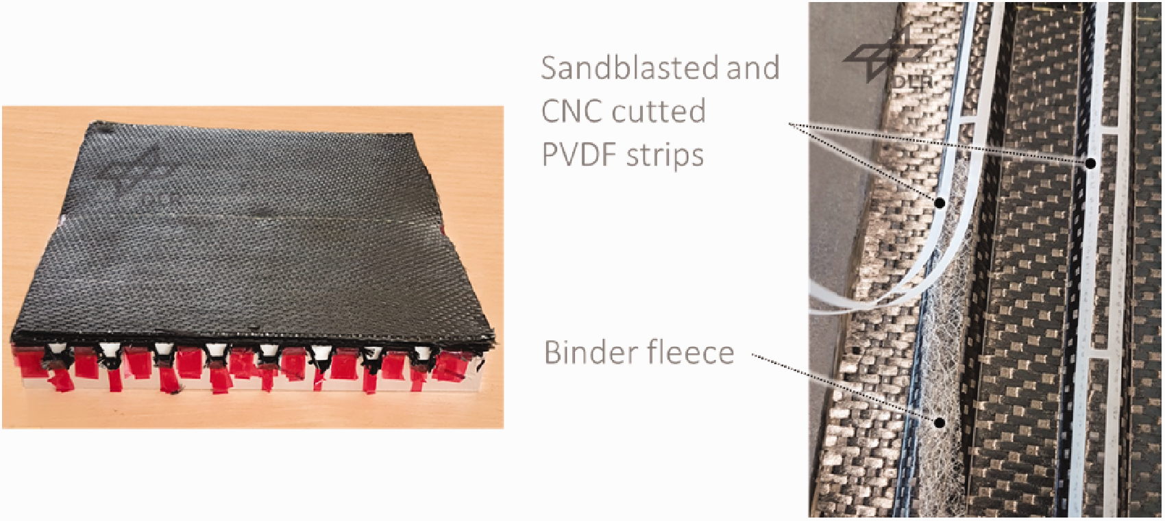
Manufacturing preparation for preforming and the application of the Surface Toughening material (PVDF) using binder fleece and a soldering iron for activation and fixation.
Figure 10 shows the result of the cured CFRP structure after infusion process. The PVDF does not disturb the resin flow and other way around the resin does not dislocate the fixed PVDF strips during the infusion.
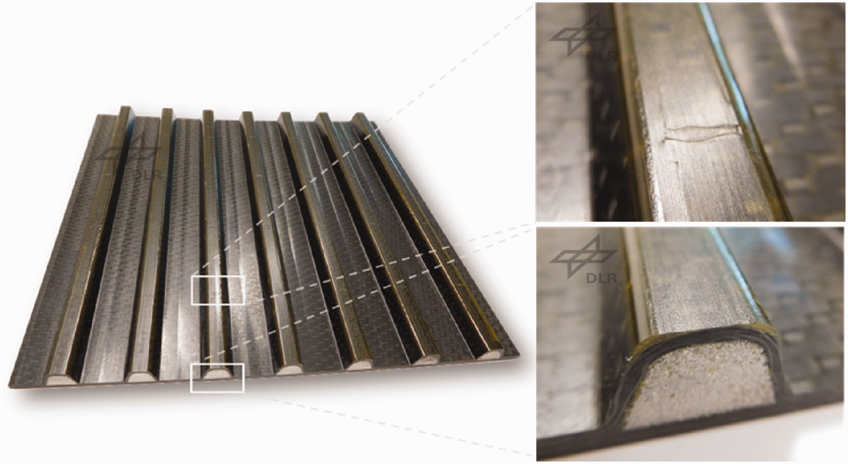
Cured CFRP structure with PVDF as Surface Toughening material, detail photos show a good melting of the PVDF and the good geometric positioning in the flanks.
The PVDF is melted and builds a good joint with the resin, which is shown in Figure 10 on the right top side.
On the right bottom side of Figure 10 the side-view of the structure is shown. There is no resin-rich area on top of the stringer and in the flank of the stringer, where the PVDF is located.
For bonding, the surfaces are cleaned with Isopropanol and prepared with 3 M Scotch Brite™. The bonding process follows the instructions of the FM94 data sheet 15 from Cytec.
Two demonstrators are manufactured; a Surface Toughening feasibility demonstrator, which is used for further investigations and a design demonstrator showing the design concept. Both are shown in Figure 11, they show that the concept and the materials can also be used in the infusion process and can be implemented well.
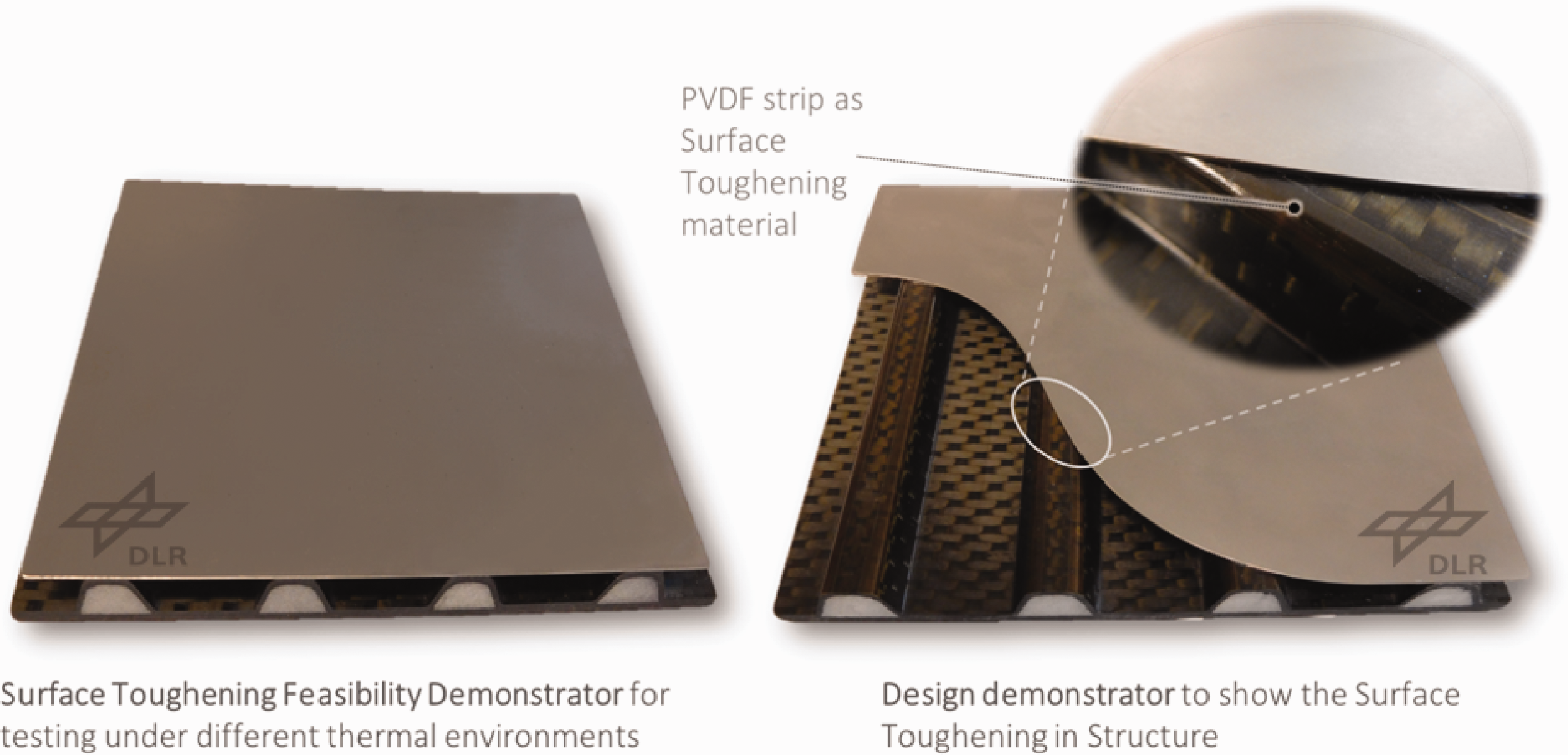
Completed manufacturing demonstrators.
Testing
In a further step the robustness of the joint is tested. Therefore the thermal conditions are simulated. Since stresses cannot be measured, the deformation of the overall structure is observed with the aid of an optical 3 D measurement technology GOM ATOS. A failure of the adhesive bondline can thus be quickly detected by stepwise changes in the deformation of the titanium skin.
Figure 12 shows the top-view of the titanium skin. The colours indicate the deviations to a virtual plane, fit to the surface on identical four points of each. Since the CFRP structure is manufactured without spring-in compensation, it has a slight curvature. This can be seen in Figure 12 in the 120 °C image. In the manufacturing process, the thin titanium skin presses against the stringers through the vacuum bag and is fixed there by the curing adhesive. When cooling down, the skin continues to be fixed and shrinks, both lengthwise and crosswise. At 23 °C a slight shell shape can be detected. This is intensified when the structure cools down further. At –20°C the effect can be seen even more clearly. Nevertheless, the adhesive bondline withstands the loads, which means that the concept has been successfully tested. At each temperature a coin-tap-test was performed and showed no debonding. Lower temperatures cannot be displayed due to the ice build-up on the surface.
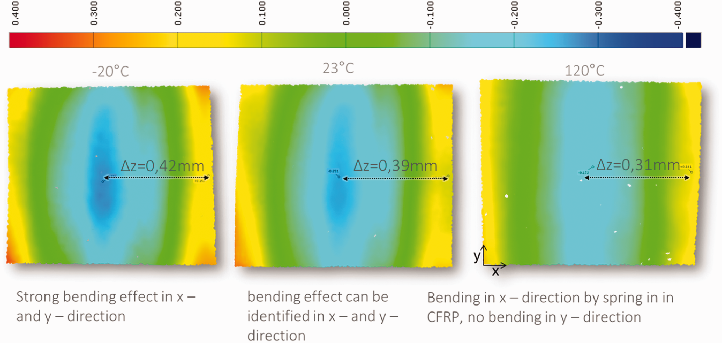
Deformations of the titanium skin from the Surface Toughening Feasibility Demonstrator at different temperatures. -20°C strong bending effect in x- and y-direction, 23 °C: bending effect can be identified in x and y-direction, 120 °C: Bending only in x-direction by not compensated spring-in effect of CFRP curing.
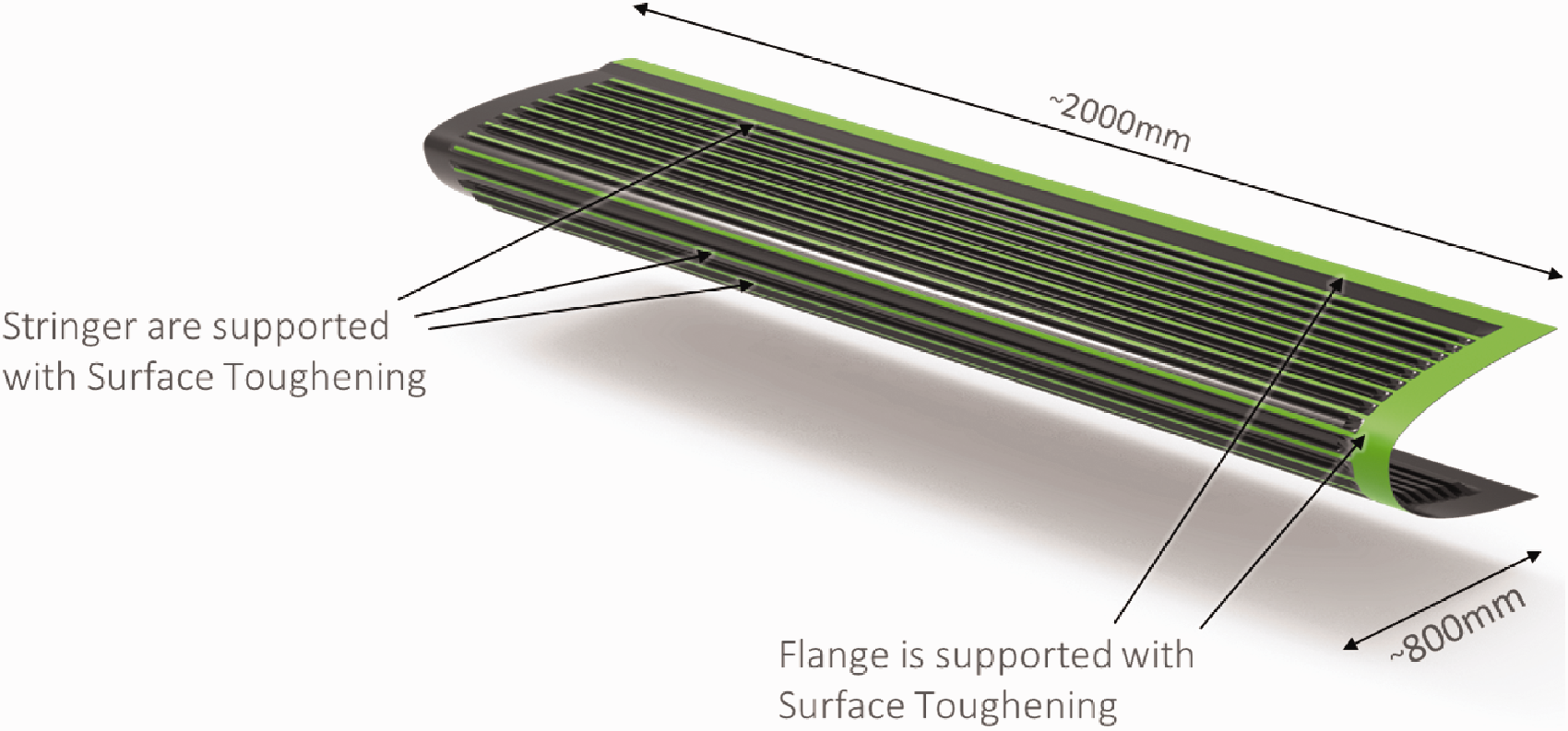
CFRP Structure of HLFC leading edge Segment manufactured by Aernnova. Green surfaces are bonding areas with the titanium skin. Two stringers in the front are.
Industrial application
The technology, which was successfully demonstrated in the small scale demonstrator, will now be applied to a 2 m HLFC leading edge demonstrator of an A350 HTP segment from Clean Sky II HLFC on HTP project. The design of the leading edge is developed by Aernnova and also the manufacturing is coordinated and executed by Aernnova.
The DLR supported Aernnova with sandblasted and CNC cut PVDF strips. The Surface Toughening is applied to all critical heads of the stringers which were applied on the areas shown in Figure 13. The front stringers are supported with Surface Toughening to increase the joint strength, while the flanks are supported to prevent a crack growth. However, since preforming a curved structure made of CFRP is more complicated than preforming a flat structure, the PVDF strips cannot be applied as precisely as laboratory tests have shown. The stringers are slightly curved, which does not create precise edges for placement and requires the technician to work by feeling. This can be seen in Figure 14.
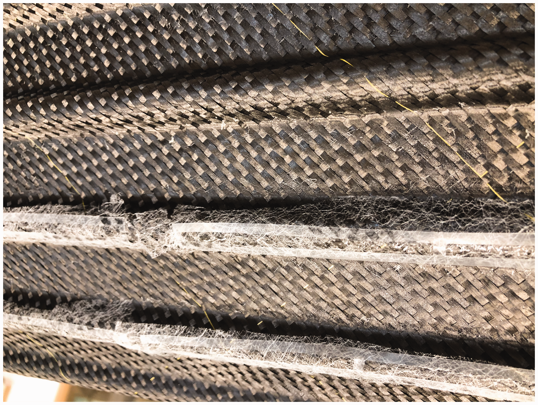
Curved form of CFRP leading edge substructure-preform with applied PVDF Strips. Variations in the orientation of the PVDF strip on the slightly round stringer heads can be seen. View to the front stringers.
Figure 15 shows the cured structure with detail on an area with PVDF. In contrast to the laboratory test, the film is located directly on the surface. Visually, the areas with PVDF film glitter and do not look smooth. One reason for this could be, in contrast to the laboratory tests, the large dimensions and mechanical tolerances lead to a lower local pressure on the PVDF film by mold. Therefore the thermal expansion of the PVDF is not limited. If the film shrinks again after cooling, it becomes wavy and looks like air inclusions. For further processing, however, the structure is grinded and the surface becomes smooth again. There are no mechanical restrictions as a consequence. However, where the PVDF strip does not lie on the edge, the positive advantage of Surface Toughening will not work. As an improvement for positioning in this case, on the one hand the strips have to become stiffer. This can be achieved by positioning the connecting bridges of the PVDF film more closely. On the other hand, a mold could simplify the positioning on the stringer heads.
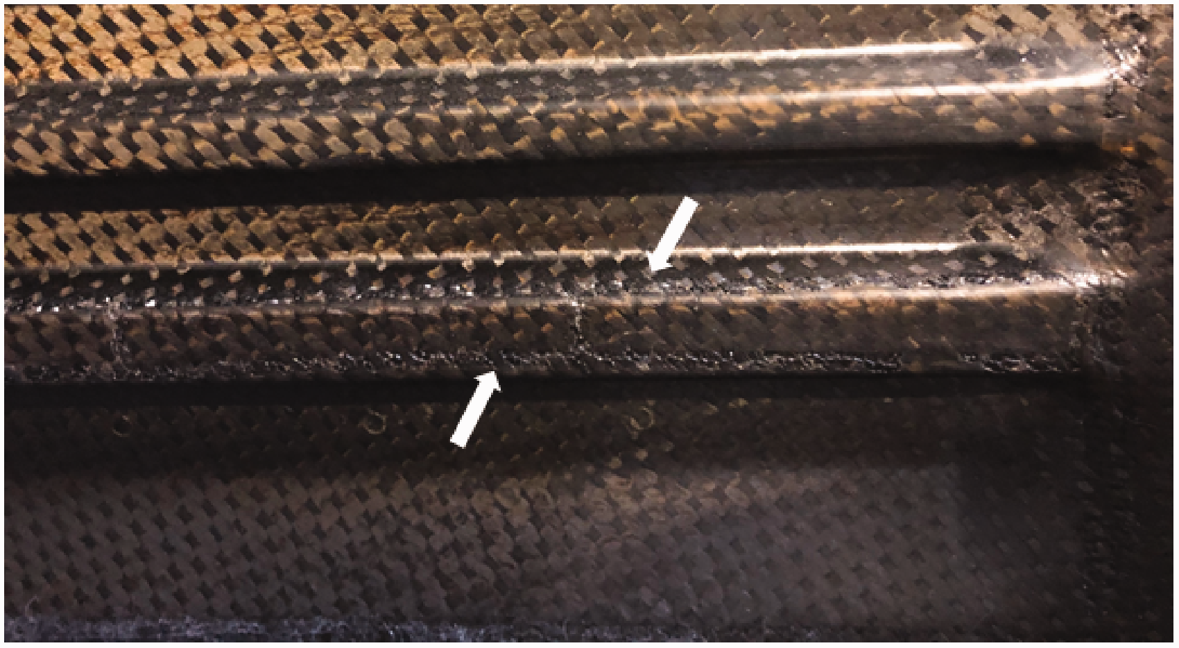
Cured CFRP leading edge substructure with PVDF as Surface Toughening on the lower stringer. A deviation of the PVDF strips in the positioning is visible. View to the flange and last stringer.
Conclusion
An industrial problem is shown in which stress concentrations occur in the adhesive of a bonded HLFC leading edge in multi-material design. The Surface Toughening concept is a potential solution for this problem, as it completely meets the requirements in contrast to the known concepts from literature. In addition to an increase of the joint strength, the concept also has a crack stop capability. The effect of the technology is made visible by FEA. In a laboratory test the functionality is proven by infusion and finally transferred to a 2 m demonstrator by the industrial partner Aernnova.
Following conclusions can be drawn:
Surface Toughening has a capability to increase the strength of an overlap joint and stops crack growth. The positioning of the strips is very easy on prepreg and in small scale demonstrators, in industrial applications an inaccurate positioning quickly occurs due to the larger size and missing stiffness of the strips. The application becomes more difficult. Resin in infusion processes does not misalign the PVDF strips during curing of the CFRP An industrial partner still implements the technology into the existing manufacturing process without much preparation and conversion.
Footnotes
Declaration of Conflicting Interests
The author(s) declared no potential conflicts of interest with respect to the research, authorship, and/or publication of this article.
Funding
The author(s) disclosed receipt of the following financial support for the research, authorship, and/or publication of this article: This project has received funding from the European Union’s Horizon 2020 research and innovation program under Grant Agreement No. 807097.