
Abstract
With civil aviation growing at around 4.7% per annum, the environmental footprint of aviation is increasing. Moreover, the use of kerosene as a fuel accelerates the depletion of non-renewable fossil fuels and increases global warming. Hence, the aviation industry has to come up with new technologies to reduce its environmental impact and make aviation more sustainable. An electrically assisted propulsion system can combine the benefits of an electrical power source with a conventional turbofan engine. However, the additional electrical system increases the weight of the aircraft and complexity of the power management system. The objective of this research is to analyze the effect of an assistive electrical system on the performance of a turbofan engine for an A320 class aircraft on a short-range mission. The developed simulation model consists of an aircraft performance model combined with a propulsion model. The power management strategy is integrated within the simulation model. With the proposed propulsion system and power management strategy, the electrically assisted propulsion system would be able to reduce fuel burn, total energy consumption, and emissions for short-range missions of around 1000 km.
Keywords
Introduction
Aviation is at a crossroad, on one hand, aviation is growing at approximately 4.7% per annum and is poised to grow at the same rate for the next couple of decades1,2 and on the other hand, the environmental impact of aviation is increasing and sustainability of aviation is being questioned. 3 Since the majority of aircraft emission occurs within the sensitive layers of the atmosphere, near the tropopause, 4 the environmental impact of aviation is not just limited to CO2 emission but entails the contribution from other sources like NOx, H2O, soot, contrail formation, etc. 5 As a result, both ACARE and NASA have set ambitious goals to reduce emissions of future aircraft.6,7.
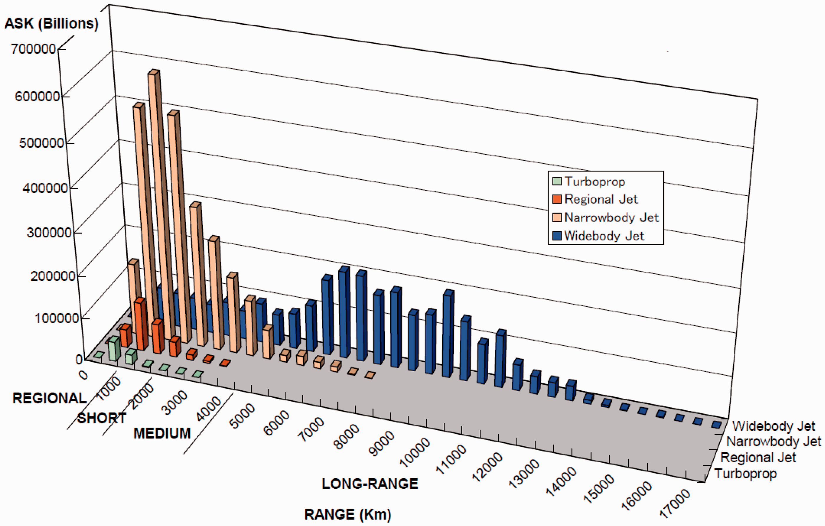
The majority of civil aviation is dominated by intercity air traffic on the short range, as shown in Figure 1(a),
8
which is mostly flown by single-aisle aircraft. Narrow-body jets can cover a range of between 500 and 4500 km and, as can be seen in the figure, are mainly operated on routes in the range up to 2000 km. In 2015, around 13,563 narrow-body jets with 100 to 229 seats were operated and it is anticipated that the number of single-aisle aircraft will increase to 24,904 in 2035, forming around 65% of the entire flying fleet.
9
Thus, reducing the environmental impact of single-aisle aircraft will have a substantial effect on the entire civil aviation.
Distribution of available seat kilometers with route distance for the year 2009.
8
Due to the advancement in battery technology, the automotive industry has managed to lower its environmental impact with hybrid and fully electric cars. In the aerospace industry, the concept of all-electric and hybrid electric propulsion is being introduced on general aviation airplanes. The Airbus E-Fan and Pipistrel Panthera are good examples of all-electric and hybrid electric general aviation aircraft. However, the restricted power-to-weight ratio of electric components holds back the development of a fully electric commercial passenger aircraft, as high power requirements make it difficult for current electric technology to meet the required performance. Therefore, the turbofan engine is still required to propel the aircraft. Combining the state-of-the-art turbofan engine with an electric motor could be a potential solution to meet the future requirements of air travel. Such a propulsion system is called the hybrid electric propulsion system (HEPS).
Different examples of HEPS applications for aeronautics have been developed.10–13 They show that the use of HEPS has the potential to increase efficiency and reduce emissions and, therefore, are in line with the future goals for civil aviation. However, successful application of these concepts depends on a number of factors, the increase in weight and complexity being one of the most crucial. Moreover, sizing becomes complicated if propulsive power comes from two different types of energy sources. The determination of the ratio of power coming from both energy sources is an important parameter for the power management system and in the sizing of HEPS. It determines the amount of electrical and chemical energies to be carried on board and the weight of power components. Hence, the feasibility of HEPS and its potential to meet the requirements depends to a large extent on the power management strategy of HEPS. 14
Power management strategies on hybrid systems have been well established in the automotive industry; however, they are still being explored in the aerospace industry. Over the years, different HEPS concepts have been investigated for aircraft. These HEPS concepts can be categorized by the way in which the gas generator and electric part are combined to drive the propulsor: series, parallel, or a combination of both.15,16 A series configuration means that the propulsor (fan/propeller) is powered by electric motors only, which in turn are driven by electric power produced by the turbo-generators. In a parallel configuration, the power is supplied by both electric motor (powered by a battery) and the turbogenerator. In the series/parallel configuration, the combustion engine can drive both electric generator and the propulsor (fan / propeller). The electric generator is linked to the electric motor that subsequently will drive the propulsor. The main difference with the series architecture is that the combustion engine is also directly connected to the propulsor. Moreover, the electric motor is also able to drive the propulsor independently. To summarize, the architecture is defined by the way in which the power from a combustion engine and an electric drive are combined to drive the propulsor.
The series architecture has been investigated by various authors.12,17,18 They analyzed the series architecture of a distributed propulsion system on a hybrid wing body configuration. In the series configuration, the extra generator not only adds weight but also induces an extra energy conversion penalty. In order to utilize the benefits of the series architecture, the aircraft configuration needs to change significantly. This study is aimed at analyzing the feasibility of HEPS in the context of a conventional single-aisle aircraft. Therefore, an evolutionary approach to HEPS based on a parallel architecture is investigated.
Electrically assisted propulsion system
A HEPS can be defined as a propulsion system that combines a conventional propulsion system with an electrical propulsion system in order to achieve better overall performance and/or lower emissions. 19 This paper focuses on an electrically assisted propulsion system (EAPS), a variation of HEPS in which the electrical system is used as a secondary system that would be running in parallel and would assist the existing propulsion system in certain flight phases to increase the overall efficiency. The EAPS system is considered in this paper because the energy-to-weight ratio of electrical batteries is significantly lower than those of the conventional propulsion system and hydrocarbon fuel. Thus, using the electrical system as a secondary system to assist the primary propulsion system can have larger benefits than using the electrical system alone as a primary propulsion system. Therefore, the EAPS configuration might have a better potential to reduce the overall environmental footprint of the aircraft, as it exploits the electric components to compensate for the lack of performance from conventional propulsion systems in the off-design condition. The turbofan engine may be sized specifically for one phase (e.g. cruise) of the mission, thereby allowing the turbofan engine to be more efficient.
The objective of this research is to analyze the effect of an assistive electric system on the performance of a turbofan engine during the flight mission of a narrow body single aisle aircraft, similar to the A320, as these aircraft have the largest impact on air transportation system. In order to analyze the aircraft with EAPS over the complete flight mission, the power requirements are derived from a flight performance model of the aircraft, developed in MATLAB® 20 and Simulink® 21 environment. To simulate the turbofan engine, GSP®22,23 is used and is coupled with the aircraft simulation model by GSP API®. 24 Finally, the EAPS and its power management strategy are modeled and integrated within the MATLAB® environment.
The system architecture
Due to the assistive nature of the electrical system in EAPS, the engine can be down-sized and designed optimally for the cruise condition, while relaxing some of the off-design constraints like take-off and climb. In this research, the electric motor is attached to the low pressure (LP) spool of the turbofan engine to assist the engine during off-design conditions.
In a turbofan engine, part of the inlet air is compressed by a fan, which bypasses the core engine. Accelerating a large amount of air through the bypass increases the propulsive efficiency and therefore yields a more efficient propulsion system. 25 However, increasing the bypass ratio (BPR) reduces the specific thrust. A higher BPR also increases the thrust lapse rate, which is the variation of thrust with altitude.
The engine efficiency is maximum when operating closer to its design point. Hence, the design point is an important aspect of the engine. The engine efficiency can thus be increased either by moving the operating conditions closer to its design point or by relaxing the constraints posed by the off-design operating requirements. In the proposed EAPS, the power node is mechanical, which means that the mechanical power produced by the motor is added to the mechanical power provided by the low-pressure turbine (LPT) of the turbofan engine. Figure 2 shows a schematic of the investigated EAPS architecture.
14
Schematic layout of the proposed electrically assisted propulsion system.
14
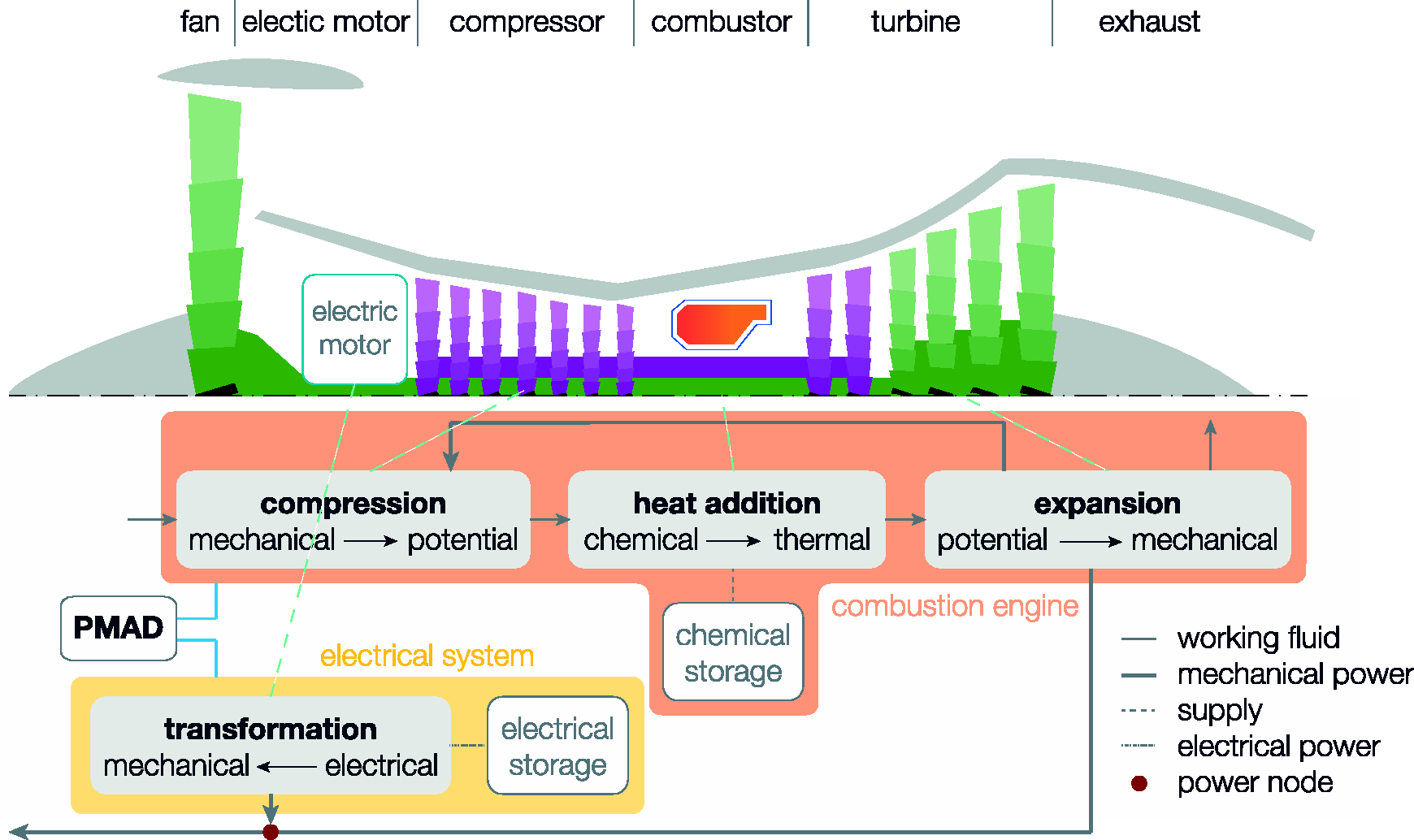
The electric motor is powered by a battery and is attached to the LP spool. The electric motor is able to drive the LP spool and thereby the fan. This allows all-electric operation for low power requirements, like idling and taxiing. For higher power requirements, the electric motor is used in conjunction with the turbofan and for medium power settings, the turbofan engine is used alone. Thus, the power supplied by the electric motor can be combined with the power from the LPT to increase the overall efficiency. The power management and distribution (PMAD) component determines the power split between the electrical system and the turbofan engine.
One of the main advantages of parallel HEPS is that the electrical system and the turbofan engine can operate independently and in conjunction. This allows temporary operation with either the engine and or electric motor, thereby increasing the overall system reliability, an important factor to be considered in civil aviation. Having a parallel configuration also enables the independent design of the power share between both sub-systems. Moreover, the power provided by the electric motor with respect to the power provided by the engine can be adjusted during operation. 26 If required, the excess power from turbofan can be used to charge the battery under specific flight conditions. However, this aspect has not been dealt with in the current paper.
Metrics for performance and sizing
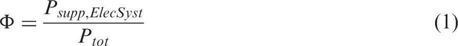
In a HEPS, the energy comes from two different sources, chemical energy from fuel and electrical energy stored in the batteries. Although the efficiency of electrical components is significantly higher than the turbofan engine, the specific energy density of batteries is substantially lower than kerosene. This significantly affects the overall aircraft weight and thereby the required energy to propel the aircraft. The power management strategy plays an important role in optimizing the overall fuel burn and energy consumption of the aircraft. The power split is the power supplied by the electric system to the fan (
As the power split determines the ratio of electric power supplied, the overall efficiency of the propulsion system will change as the efficiency of the electrical system is higher than the turbofan engine. Conventional propulsion systems can be compared by their thrust specific fuel consumption (


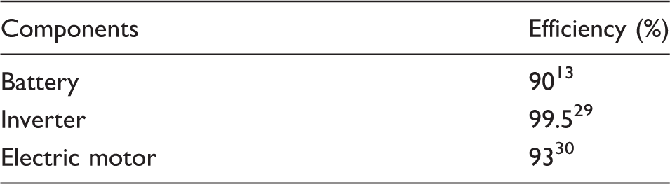
The main components that affect the weight of the electric system are the battery, the inverter, and the electric motor. The development of the technology in electrical components can be expressed in terms of specific power or specific energy. Figure 3 displays the anticipated development of electric component technology as predicted by Rostek.
28
.
Performance targets on system component level; presented by Rostek.
28

Overview of electric system components assumptions.
Modeling environment
The aircraft model
To simulate the effect of power management strategy, a flight performance model of the Airbus A320 was developed and is used to determine the power requirements for a 1000 km flight. This simulation model has been developed in MATLAB®
20
and Simulink®
21
environment. The flight performance model uses the basic equations of motions to simulate the state of the aircraft, as described by the following equations
31


The input for the flight performance model is the along-track distance, calibrated airspeed (
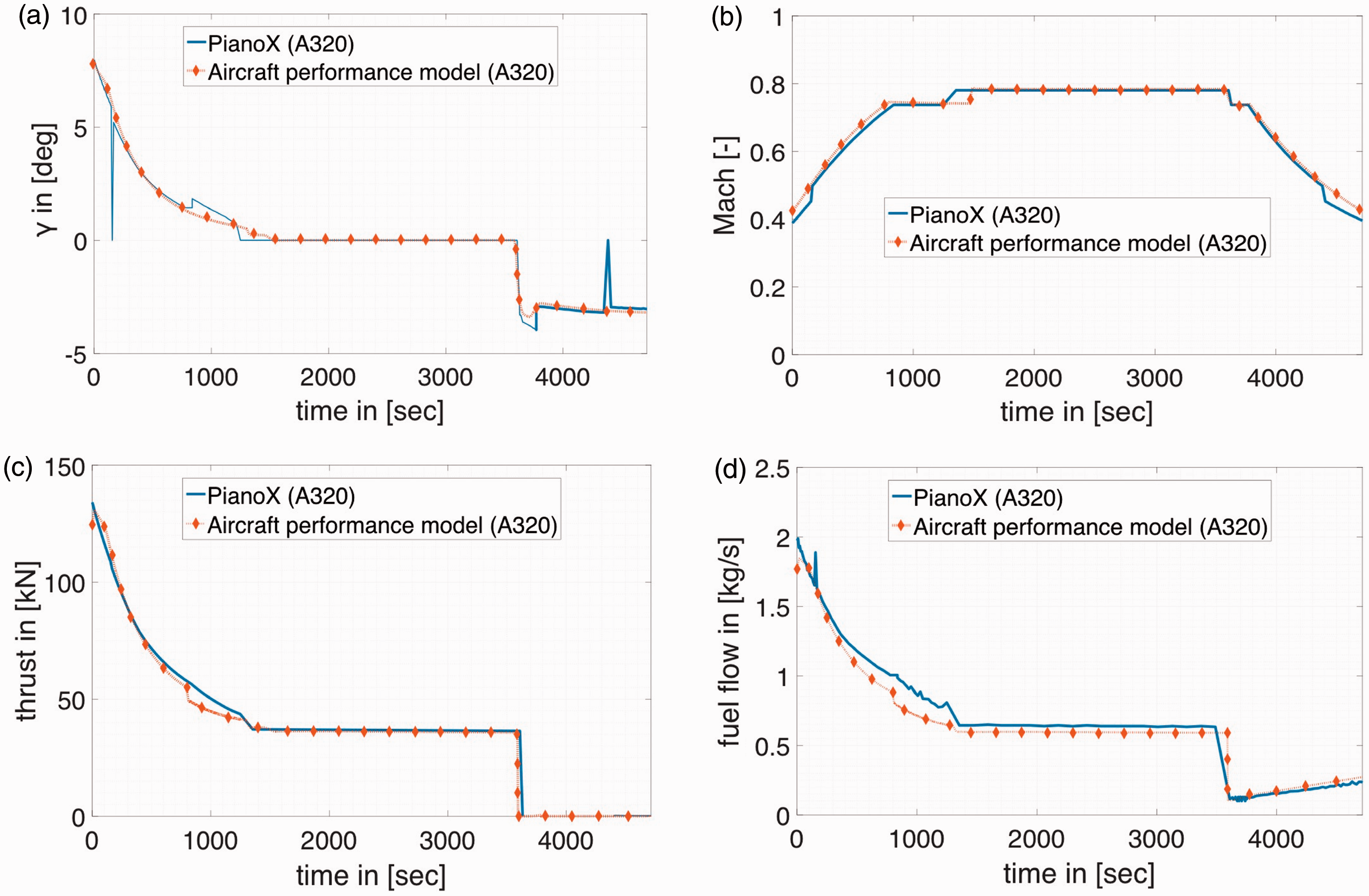
To validate the aircraft performance model, the model output is compared with PianoX®, a performance analysis software that calculates the performance characteristics of a specified aircraft in its database for a given range and payload (fuel consumption, emissions, drag, etc.). This research is not focused on attaining an accurate flight mission, but to analyze the effect of an EAPS on a reference flight. Therefore, comparison with PianoX® is carried out in a qualitative manner to see if similar trends could be observed from both models. As a validation of the flight mission analysis module, a 1000 km flight mission of Airbus A320 is simulated and compared with PianoX®. The aircraft mission is shown in Figure 4(a) and (b) and the comparison of the flight path angle, Mach number, thrust, and fuel flow are shown in Figure 5(a) to (d). It can be seen that the results from the two models are in good agreement with each other. The discrepancy in the fuel flow is mainly due to the different engine model used in the current analysis as compared to PianoX®, which will be explained in a later section of the paper.
(a) Mission altitude profile; (b) aircraft true airspeed. (a) Flight path angle; (b) flight Mach number; (c) aircraft thrust requirement; (d) engine fuel flow.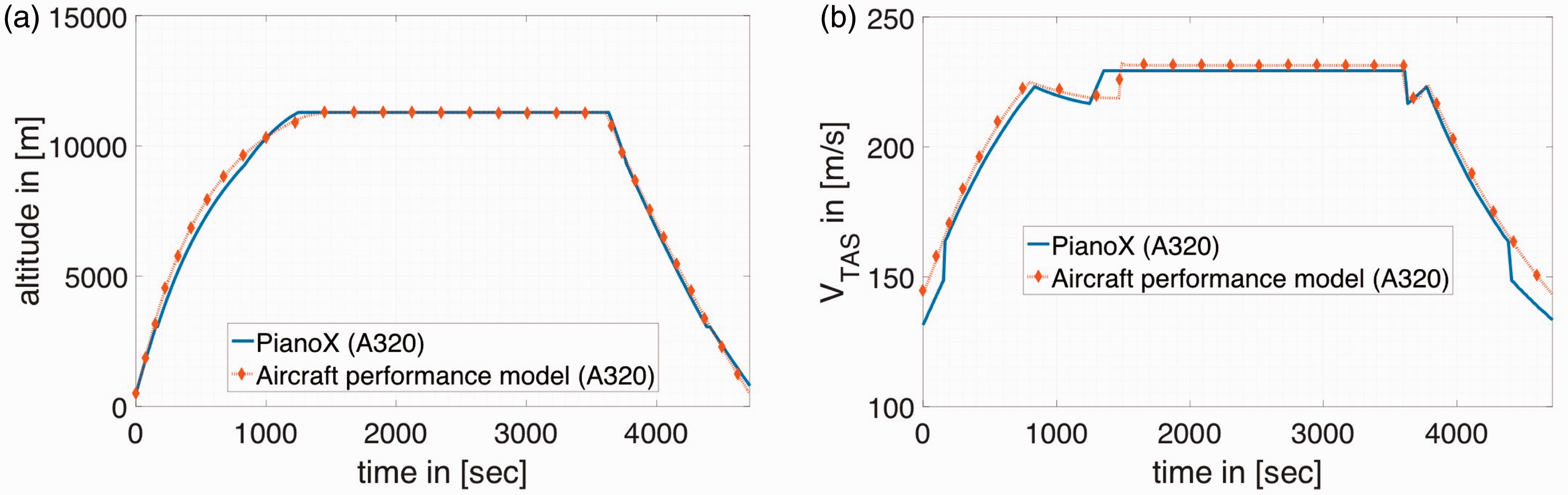
The engine model
To simulate the CFM LEAP-1A turbofan engine performance, the engine has been modeled in GSP®. The GSP® is a component-based, 0D thermodynamic analysis platform for gas turbines, developed jointly by NLR and TU Delft. It provides a flexible platform to model various types of gas turbines as various components can be connected appropriately to simulate any gas turbine architecture. This flexibility in components assembly is especially beneficial in analyzing novel engine architectures. The required power and state of the aircraft (altitude, Mach number) are inputs to the engine model. These inputs are provided by the flight performance model to the engine model using GSP API®. For modeling the engine in off-design conditions, turbomachinery maps have been scaled and fine-tuned using the methodology elaborated by Rademaker 32 .
The output of the engine model is the fuel flow, which affects the aircraft weight and thereby its required thrust. GSP® is also able to compute the approximate values of the engine emissions. While the major products of combustion like CO2 and H2O are mainly dependent on the fuel consumption, the minor species of combustion like NOx, CO, UHC (unburnt hydrocarbon), and soot are mainly dependent on the chemical kinetics, combustion technology, combustor design, and combustor operating conditions. There are several ways of evaluating these emission in GSP®, namely, the NLR Emission Model, the semi-empirical method, and the multi-reactor combustion model. 24 In the current research, the NLR emission method is used in which data available from the ICAO emission certification databank (for NOx, CO, UHC emission index data, and smoke number data) at specific engine thrust settings are used to predict the combustor emission characteristics. The emission index at off-design conditions is then calculated using logarithmic interpolation with combustor temperature and empirical corrections for deviating combustor pressures.
Scaled emission data used for GSP®.
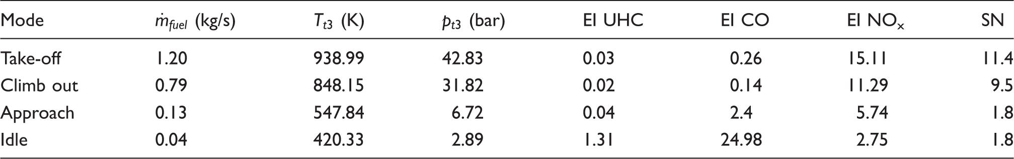
Figure 6 shows the engine model within the GSP® environment. The output of the engine model is used to determine the effect of EAPS and its power management strategy.
The CFM LEAP-1A turbofan engine model in GSP®.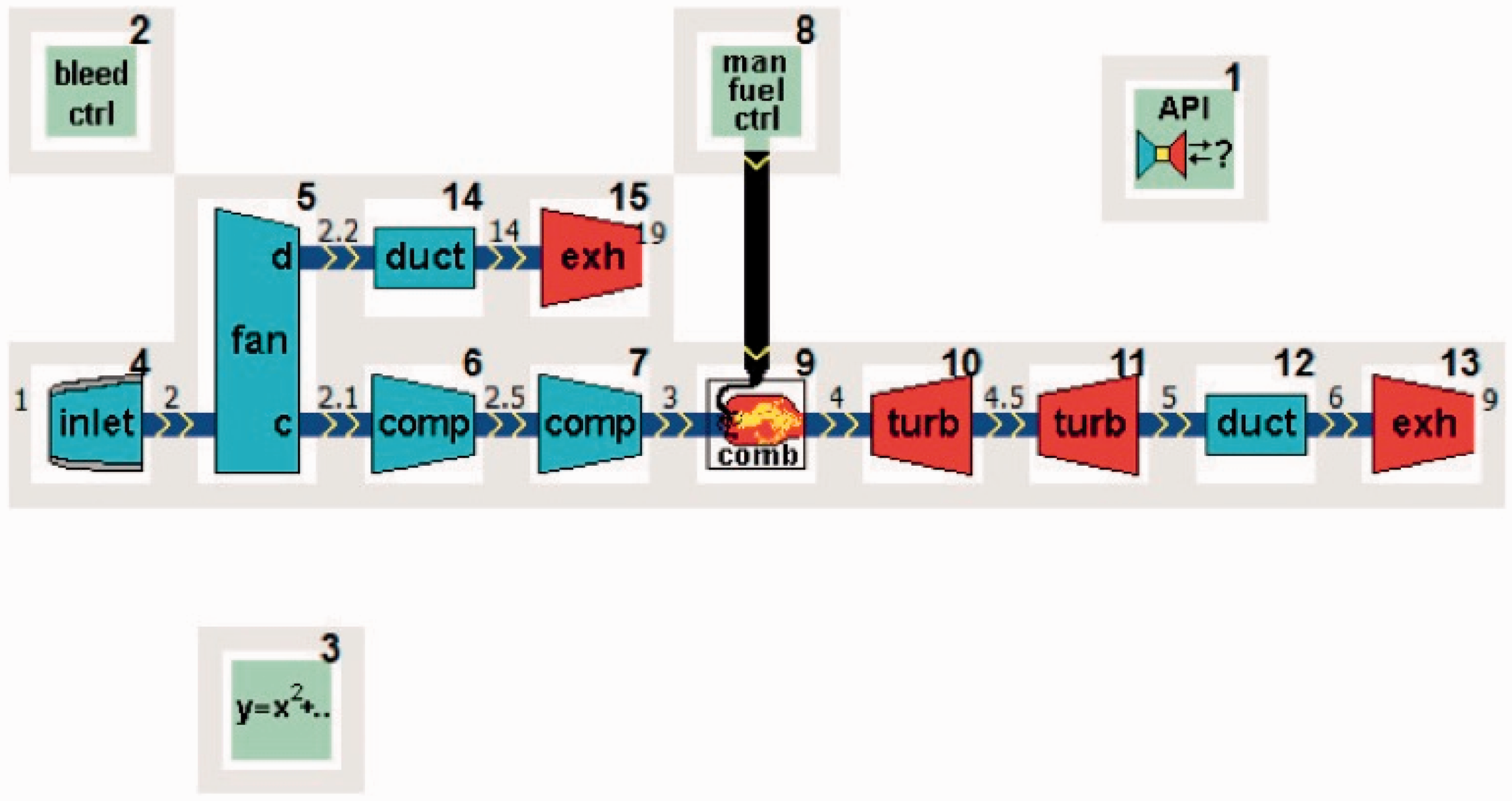
Figure 7 compares the emissions obtained from the GSP model with PianoX® for Airbus A320. Both simulate the emissions of Airbus A320, but since the CFM LEAP-1A engine modeled in GSP is a new engine compared to the A320 model in PianoX® with the CFM-56 engine, it can be seen from the figure that emissions from LEAP-1A engine are significantly lower as compared to the CFM-56 engine. The reduction in CO2 emissions is 12.2%, which resembles the expected reduction, as stated by the OEM.
34
This proves that the engine model developed in GSP® is reasonably good to carry out further simulations.
Comparison of fuel burn dependent emissions between simulation model and PianoX® for a specified mission of 1000 km.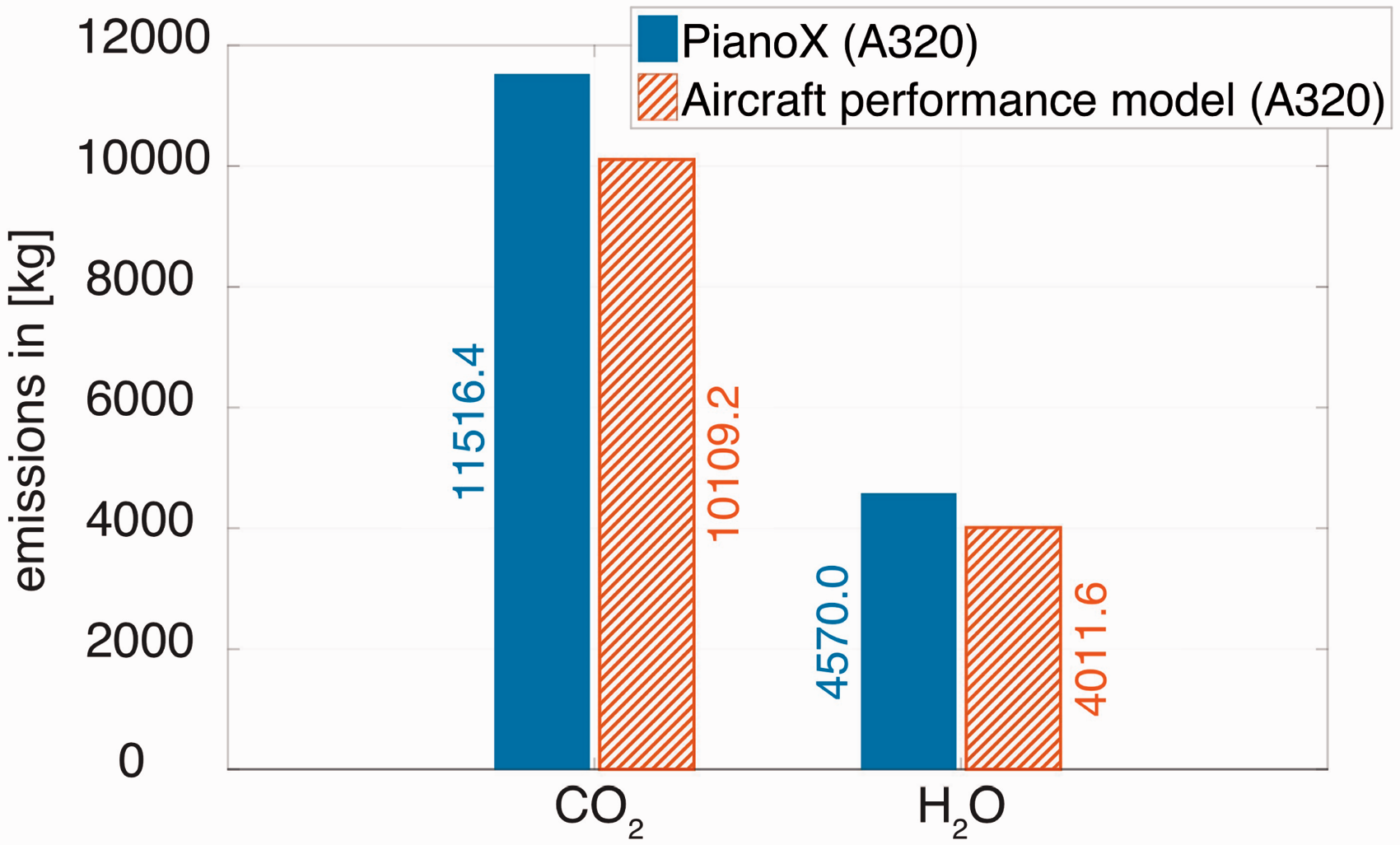
The GSP model for the LEAP engine is extended for the proposed EAPS system by adding the power provided by the electric motor to the LP shaft of the turbofan engine. The power management strategy determines the amount of electrical energy to be carried onboard and the amount of (peak) power to be supplied, essential for sizing of the electrical system. To integrate the power management strategy and thereby sizing of the electrical system, several calculation steps are required. Such a methodology has been presented by United Technology Research Center (UTRC) 35 .
The EAPS simulation
To evaluate the feasibility of the proposed EAPS system, first, the reference flight mission is simulated. This step is needed in order to determine the LP shaft power during flight. In the second step, part of this shaft power is then supplied by the electrical system; depending on the power split ratio. In the third step, the mass of the electrical system is computed and is added to the aircraft mass. Due to the additional mass, the thrust requirement of the aircraft changes, resulting in new LP spool shaft power. Lastly, the motor power determined in the second step is added to the required engine shaft power computed in the third step. Figure 8 shows the various simulation steps in the form of a flow diagram.
Schematic of the simulation model.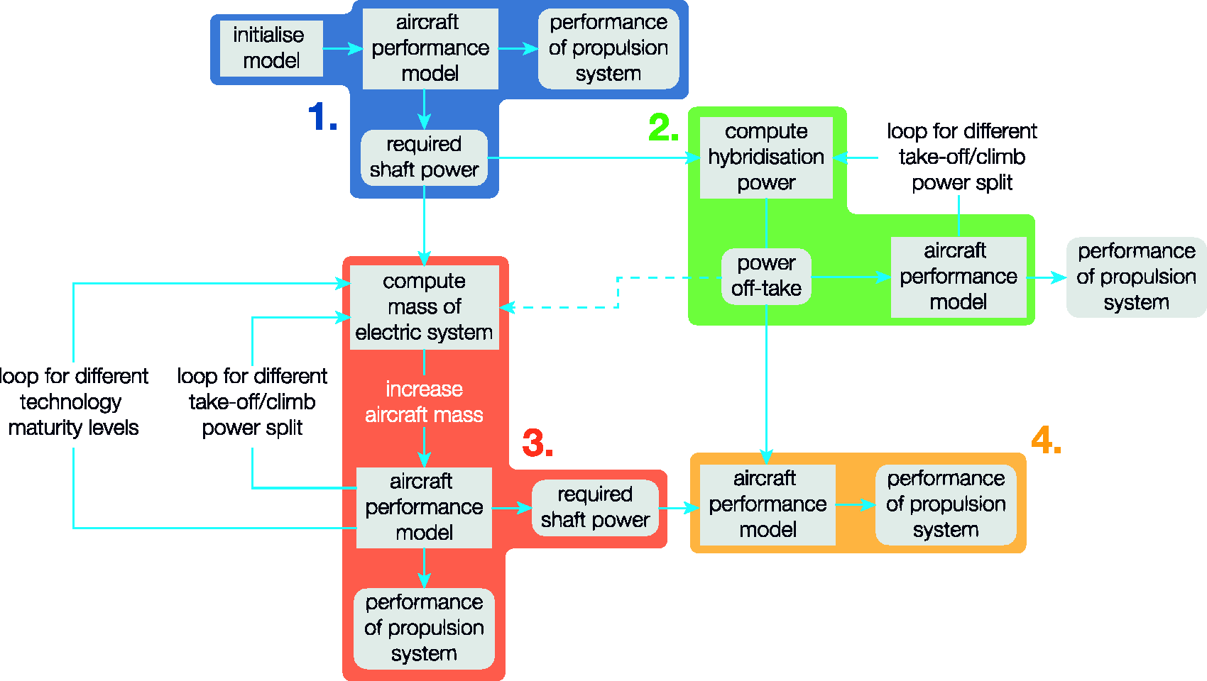
Power management strategy
During the entire mission, the power management strategy determines when and how the electrical system would assist the turbofan engine. Consequently, the weight of the electrical system follows from the power management strategy, as the weight is determined by the amount of electric power and energy to be available during the flight. The additional weight of the electrical system should be offset by its performance, and therefore to analyze the effect of a power management strategy from an overall mission perspective, a global optimization methodology is applied.
In terms of the turbofan engine design condition, there are several definitions, as shown in Figure 9.
36
A valid engine design should meet performance requirements under all operating conditions. The conventional approach of ensuring feasibility of an engine design involves iterative loops between the design condition and off-design conditions such that the final engine design can satisfy the operating constraints in the entire flight envelope
25
.
Various engine design conditions.
36
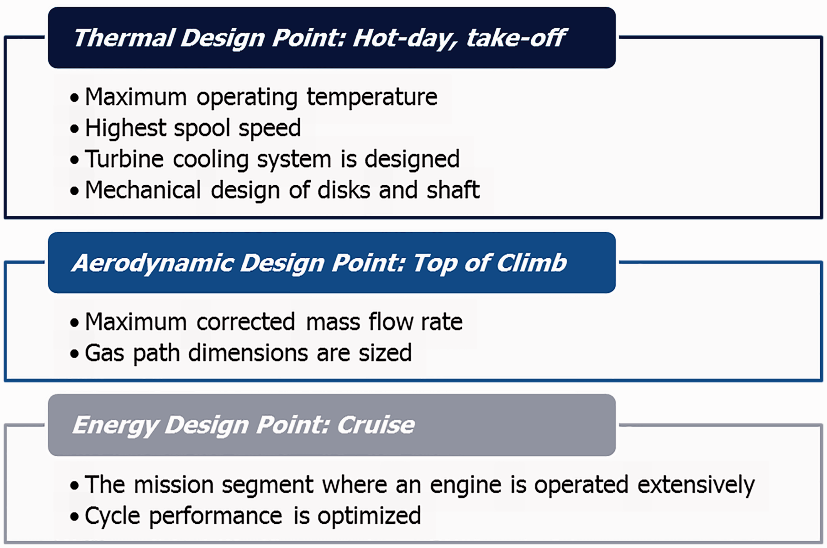
If the constraints on hot day take-off and top of climb could be eased due to the assistance of electrical power, the engine can be optimized for the cruise condition, thereby reducing the cruise SFC. Also, for very low thrust requirements like taxiing and idling, engine performance in terms of fuel consumption and engine emissions can be reduced substantially as electric taxiing would reduce noise and emissions at airports significantly.
Figure 8 shows the power management strategy considered in this research. It is segmented into the following flight phases, as shown in Figure 10.
Taxi-out: fully electric. Take-off: assistance of electric system (controlled with the take-off power split). Climb: assistance of electric system (controlled with the climb power split). Cruise: turbofan engine only. Descent: turbofan recharges the electric system. Taxi-in: fully electric. Power management strategy during flight mission.
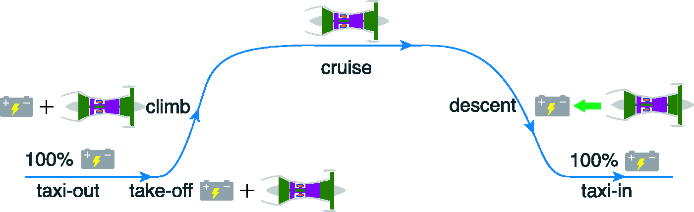
In this power management strategy, the power split is a percentage of the average power per flight phase. The power supplied by the electrical system is constant during each flight phase and corresponds to this percentage.
The input variables for the power management strategy are the take-off and climb power splits. The power split during take-off lowers the maximum thrust required from the turbine engine, whereas power split during climb increases efficiency. The take-off and climb power splits have a substantial effect on the sizing of the electric system and on the weight of the aircraft. Moreover, as less fuel is used during taxi-out, take-off and climb, the weight of the aircraft during the cruise is different.
Engine scaling
The assistance of the electric system during take-off and climb allows the engine to be designed for the cruise phase and this has a significant effect on the engine weight and performance. In order to scale the CFM Leap-1A engine to an electrically assisted turbofan engine, various scaling parameters have been used, as described in this section. The mass of the engine is reasonably well correlated to the take-off static thrust by equation (7).
37
It should be noted that the static take-off thrust (
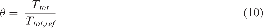
Equation (8) represents the mass flow rate scaling parameter, MSP.
38
When scaling the engine, this parameter should remain constant. For example: scaling the design mass flow rate (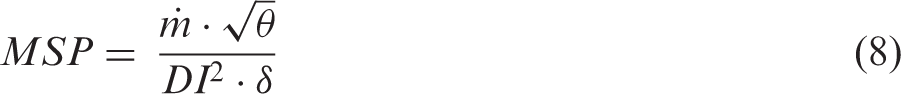

Due to the additional power delivered by the electrical system during certain flight phases, the centrifugal forces (Fc) on the fan blades increase and would lead to a heavier fan disk of the turbofan engine. Equation (11) describes the relation between the rotational speed of the blades (
Scaling of the engine is also limited by the turbine inlet temperature,
Results of the simulation
The fuel burn and total energy consumption of the Airbus A320 for a 1000 km flight mission are 3231 kg and 38.62 MWh, respectively. The electric system may reduce the fuel burn, but as fuel is not the only source of energy, the total energy consumption (fuel + electrical energy) for the mission should also be considered. Although the efficiency of the electric system is almost twice as high compared to the turbofan engine, the specific energy of the electric battery is significantly lower than the specific energy of the fuel, resulting in additional weight. With the anticipated development of electric component technology for 2030 + (see Figure 3), the sp. energy of batteries at a system level is assumed to be 600 Wh/kg. It should be noted that this is still 20 times lower than the sp. energy of the kerosene fuel (≈12,000 Wh/kg).
Due to the increase in the aircraft weight, the objective of saving fuel contradicts the objective of saving energy. Figure 11 displays a Pareto representation of the sensitivity of fuel burn and energy consumption for various sp. power and sp. energy values of electrical components. The values of sp. power and sp. energy correspond to different technology targets as mentioned in Figure 3. Each symbol represents a different technology maturity level, while each point represents a different power management strategy. As the power management strategy affects the weight of the electric system, the fuel burn and the total energy consumption are also affected. It can be seen that aircraft MTOW is exceeded for several combinations of take-off power split and climb power split.
Pareto efficiency of EAPS for electric technology targets.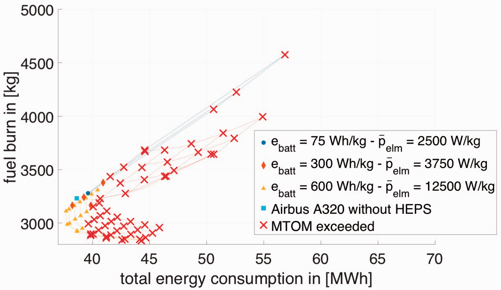
With the current electrical technology, EAPS does not show any benefit. It can be seen from the figure that aircraft total energy consumption increases significantly due to the increase in aircraft weight. With the anticipated technology maturity level of 2030, the use of an EAPS can save both fuel burn and total energy consumption. Figure 12 represents a zoomed version of Figure 11: fuel consumption (Jet-A) versus total energy consumption using electrical machines and batteries that are expected to be available in the year 2030, for several variations of power splits. The three power management strategies labeled in the figure are explored further as they offer a substantial reduction in fuel consumption while reducing the total energy consumption at the same time. For these points resizing of the engine will be considered.
Pareto efficiency of EAPS with electric technology maturity of 2030+.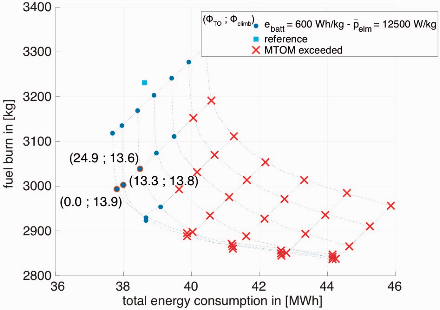
It is important to further analyze the effect of the power split on the engine design and performance on the points shown on the Pareto front of Figure 12 as the change in power split ratio has a significant influence on the engine performance characteristics e.g. extreme high shaft speeds or higher Effect of engine design mass flow scaling on engine mass, including the additional weight of redesigned disks.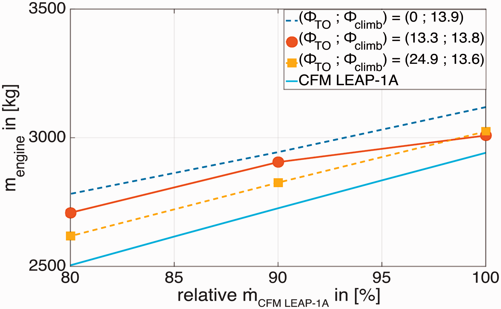
The effect of downscaling the engine on the cruise Effect of engine size and power management strategy on turbine inlet temperature.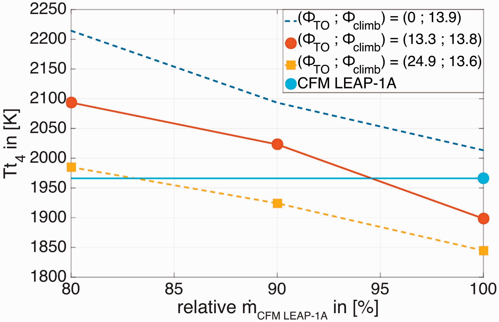
Taking the turbine inlet temperature into account, it can be seen that the power management strategy with a take-off and climb power split of 0.0% and 13.9% respectively results in an increase in Tt4. However, the power management strategy with a take-off power split of 24.9% and a climb power split of 13.6% with a downscaled engine of 90% is feasible. This would lead to a fuel saving of 7.5% and a reduction in total energy consumption of 2%. Accordingly, the CO2 and H2O emissions reduce proportionally to the fuel saving. Figure 15 shows the fuel-dependent emissions of the Airbus A320 without and with (optimized) EAPS next to each other.
Effect of proposed EAPS on fuel burn dependent emissions.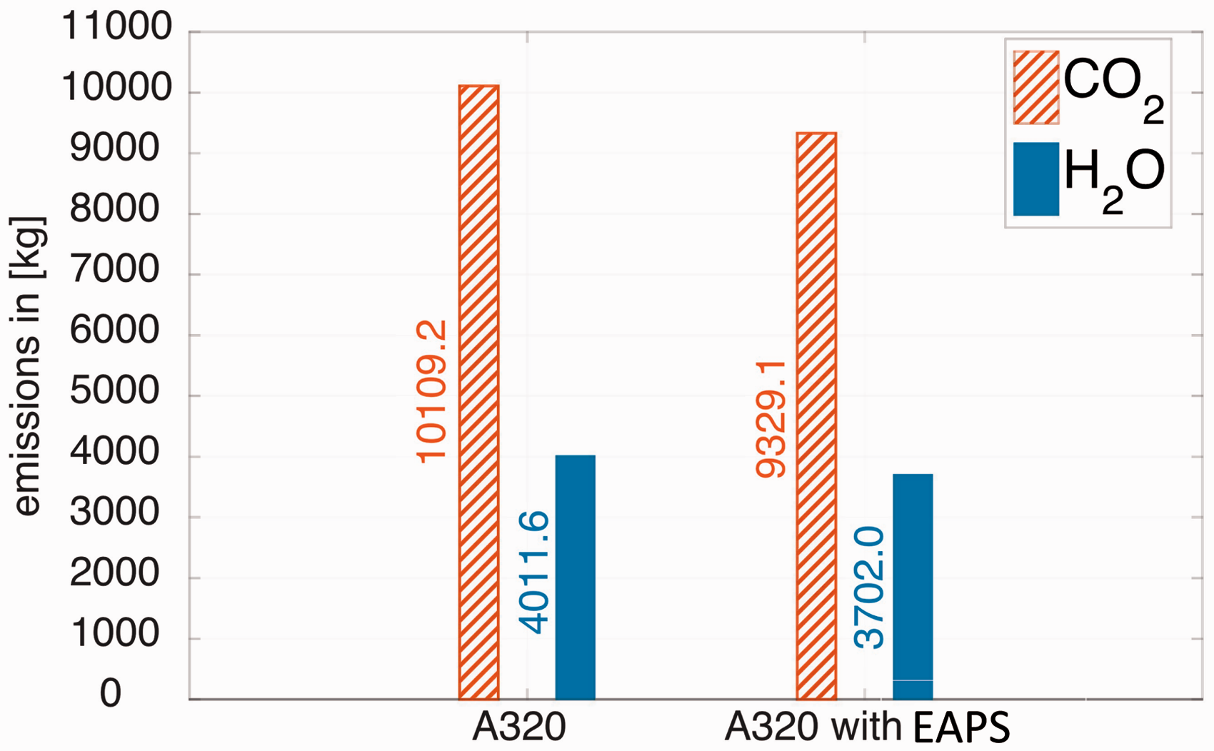
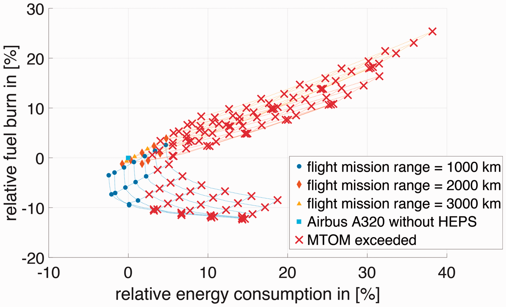
Other emission types depend on the specific operation of the engine (NOx and CO). Figure 16 depicts the effect of EAPS on emissions that are dependent on the engine thrust setting. The EAPS turbofan engine emits 5.5% fewer pollutants than the conventional turbofan engine. It should be noted that when the range is increased to 2000 km, the relative fuel burn and the energy consumption increase. This is mainly due to the weight of the batteries, which has to be carried over for a longer distance. The variation in the relative fuel burn and energy consumption for different ranges is shown in Figure 17. Thus, with the current projected technology development in electrical batteries and electrical components, the HEPS is feasible for short ranges only. Nevertheless, this is within the range that covers most of the inter-European flights.
Effect of EAPS on engine operation dependent emissions. Pareto representation of relative changes in fuel burn and total energy consumption for various mission ranges.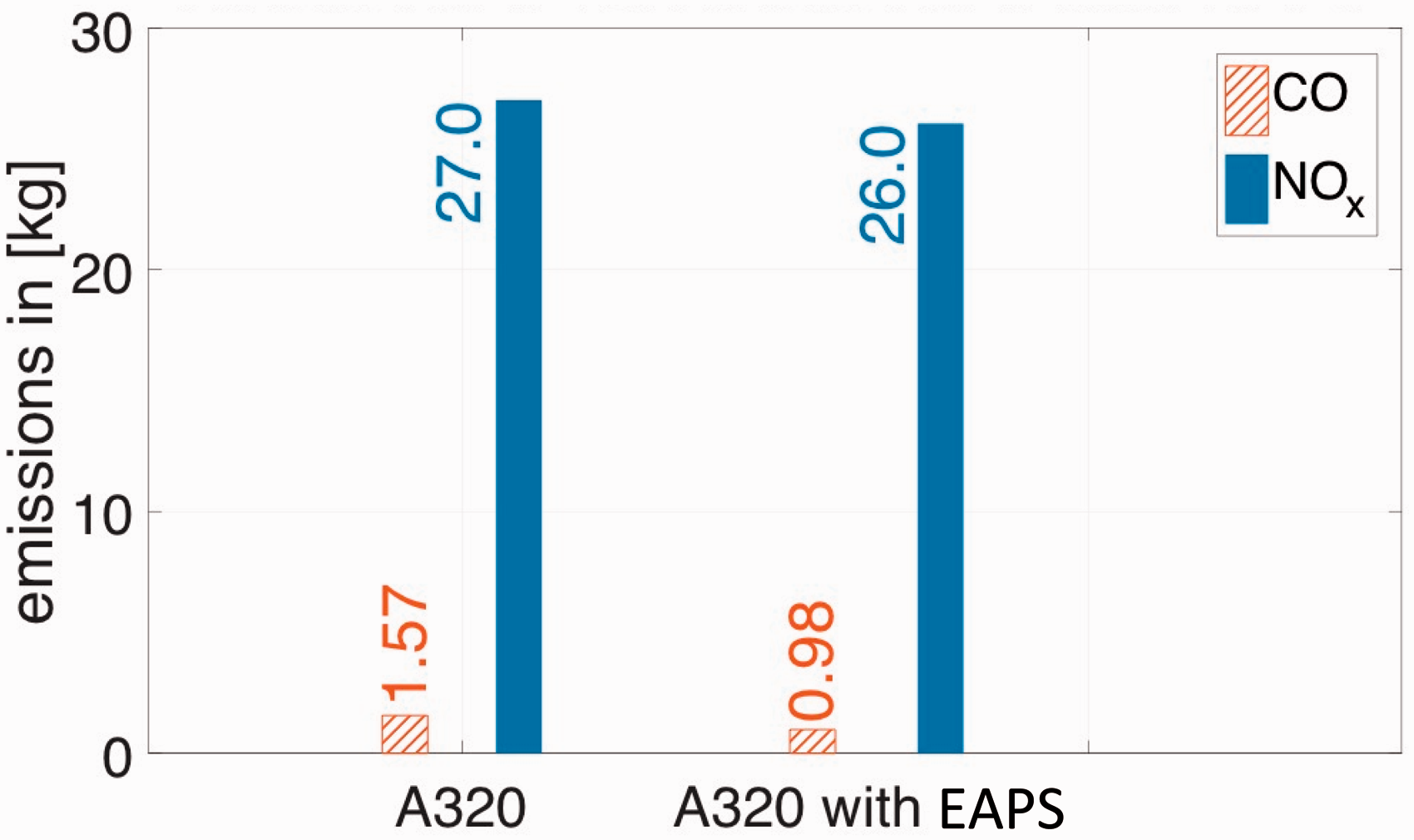
Conclusions
The developments in battery technology allowed the automotive industry to build hybrid and fully electric cars. However, for aircraft, the limited power-to-weight ratio of electrical components impedes the development of all-electric propulsion. In this regard, HEPS, especially the EAPS system is more viable. In this research, the power management strategy of an EAPS system based on a parallel HEPS architecture is analyzed for a single-aisle aircraft for a mission range of 1000 km.
The implementation of the EAPS in the mid/long-term depends heavily on the technology maturity level of the electric components. With the current technology, the EAPS would only make the aircraft heavier, without being able to save any fuel. With the predicted technology level of 2030, the parallel EAPS can be beneficial for a short-range flight of 1000 km, if an appropriate power management strategy is chosen.
In the power management strategy of this research, the aircraft is propelled electrically during taxiing and is electrically assisted during the take-off and climb phase. With a climb power split of approximately 14%, the total energy consumption and fuel burn are both reduced. A take-off power split of approximately 25% seems sub-optimal in the first place, but does allow the engine to be downscaled and operate close to its design point during the cruise. Therefore, with a take-off and climb power split of 25% and 14% respectively, the engine can be scaled down to 90%. This configuration can reduce fuel consumption by 7.5% and the total energy consumption by around 2%. The CO2 emission during the flight reduces proportionally with the fuel savings. It was observed that the proposed EAPS can reduce the NOx emission by 3.7%. The EAPS system can reduce the emission in and around airport substantially due to electric taxiing and reduced fuel burn during take-off and climb.
Footnotes
Acknowledgements
The authors would like to thank Mr Oscar Kogenhop and Mr Edward Rademaker for providing their assistance on GSP and the simulation of emissions.
Declaration of Conflicting Interests
The author(s) declared no potential conflicts of interest with respect to the research, authorship, and/or publication of this article.
Funding
The author(s) received no financial support for the research, authorship, and/or publication of this article.