
Abstract
With an emphasis on the combined degradation of railway track geometry and components, an improved numerical approach is proposed for predicting the track geometrical vertical levelling loss (VLL). In contrast to previous studies, this research unprecedentedly considers the influence of unsupported sleepers (US) configuration on VLL under cyclic loadings, elasto-plastic behaviour, and different operational dynamic conditions. The nonlinear numerical models are performed adopting an explicit finite element (FE) package, and their results are validated by field data. The outcomes are iteratively regressed by an analytical logarithmic function that cumulates permanent settlements, and by a power function factor, which innovatively extends the response of US on VLL over a long term. Results shows that at 3 million cycles (or 60 MGT) the worst configuration for 20-ton axle load is at 5 US with 5-mm gap (5,51%), whereas for 30 and 40-ton axle loads is at 5 US with 2-mm gap (1.23% and 0,89%, respectively). This indicates that the axle load affects considerably the VLL as expected, however, the US condition plays an important role to accelerate it. Based on this study, the acceptable configuration of US can be specified for a minimum effect on VLL (thresholds) and, therefore, supports the development of practical maintenance guidelines to prolong the railway track service life.
Keywords
Introduction
Nowadays, the post-construction track geometry deterioration is one of the major problems for railway track maintenance.1,2 Increasing train velocities, frequencies of railway transport, and axle loads can accelerate rapidly this deterioration due to repeated traffic loadings.2,3 Technically, this trend requires higher standards not only for each individual track component but also for the track geometry. 4
According to Dahlberg, 5 an important contribution to the track geometrical deterioration is the uneven ballast settlement, which impacts on the track geometry, specifically on one of the most important track geometrical parameters: the vertical levelling (VL). Also known as vertical profile or longitudinal level, the VL is described in BS-EN-1348-1 6 as the deviation of consecutive running table levels on any rail, expressed as an excursion from the mean vertical position. Any weakness in the railway track support system (track components) will affect negatively the railway track vertical profile. 2 It means inferior ride comfort quality and excessive dynamic forces for railway track and vehicles components, resulting inevitably in a less attractive and safe railway.2,7
Track geometrical vertical levelling loss (VLL) is defined as a parameter that represents the losses of rail vertical position in the track physical space. 2 In general, it can be described to occur in two different phases before the first railway maintenance activity: (1st) a rapid consolidation of the railway ballast directly after track construction or maintenance, and (2nd) a slower loss rate related mostly to ballast settlement.8,9 At this 2nd phase, the rate can be basically approximated by a logarithm of the number of cyclic loadings or million gross tons (MGT) as the rate of ballast plastic deformation decreases gradually. 10
In a railway track, ballast voids and pockets underneath the sleeper can occur due to unequal ballast settlements that may cause a gap between the ballast and the sleeper. As a result, one or more sleepers can be partially unsupported from the rail as some parts of rail remain suspended causing a variation of dynamic force in the track section. 11 In a poor vertical profile, large gaps can be readily observed between the sleepers and the ballast.12,13 Furthermore, considering in situ measurements, Zhu et al., 12 Zakeri et al., 13 Olsson et al., 14 Augustin et al., 15 and Sresakoolchai and Kaewunruen 16 indicated that small lacks between the ballast and the sleepers were very recurrent at an ordinary railway location (over 50%).
The dynamics forces caused by unsupported sleepers (US) are responsible for escalating the VLL under dynamic cyclic loadings, for example, by damaging the track components, particularly the railway ballast. When a local VLL varies along the railway track, VL irregularities develop further in a vicious cycle causing an amplification of the dynamic loading of track due to vehicle-track interaction. Also, as highlighted in Kempfertm and Hu,
17
Esveld,
18
and Sun,
19
the natural frequencies (or wavelengths) of a railway track structure (and components) influence on how much it vibrates under a specific train velocity,20–22 after innumerous cyclic loadings, which can negatively affect how much it deflects.
16
Moreover, because of high flexible stiffness of rail, the rail vertical displacements and their reactions on the adjacent sleepers are aggravated. Therefore, a reasonable physical understanding about the effect of US on VLL is of great interest for supporting the prediction of the long-term track geometrical deterioration by assessing the current track components or introducing new ones. Figure 1 shows some of the track components on an ordinary railway and illustrates schematically the concepts of track geometrical VL parameter and US.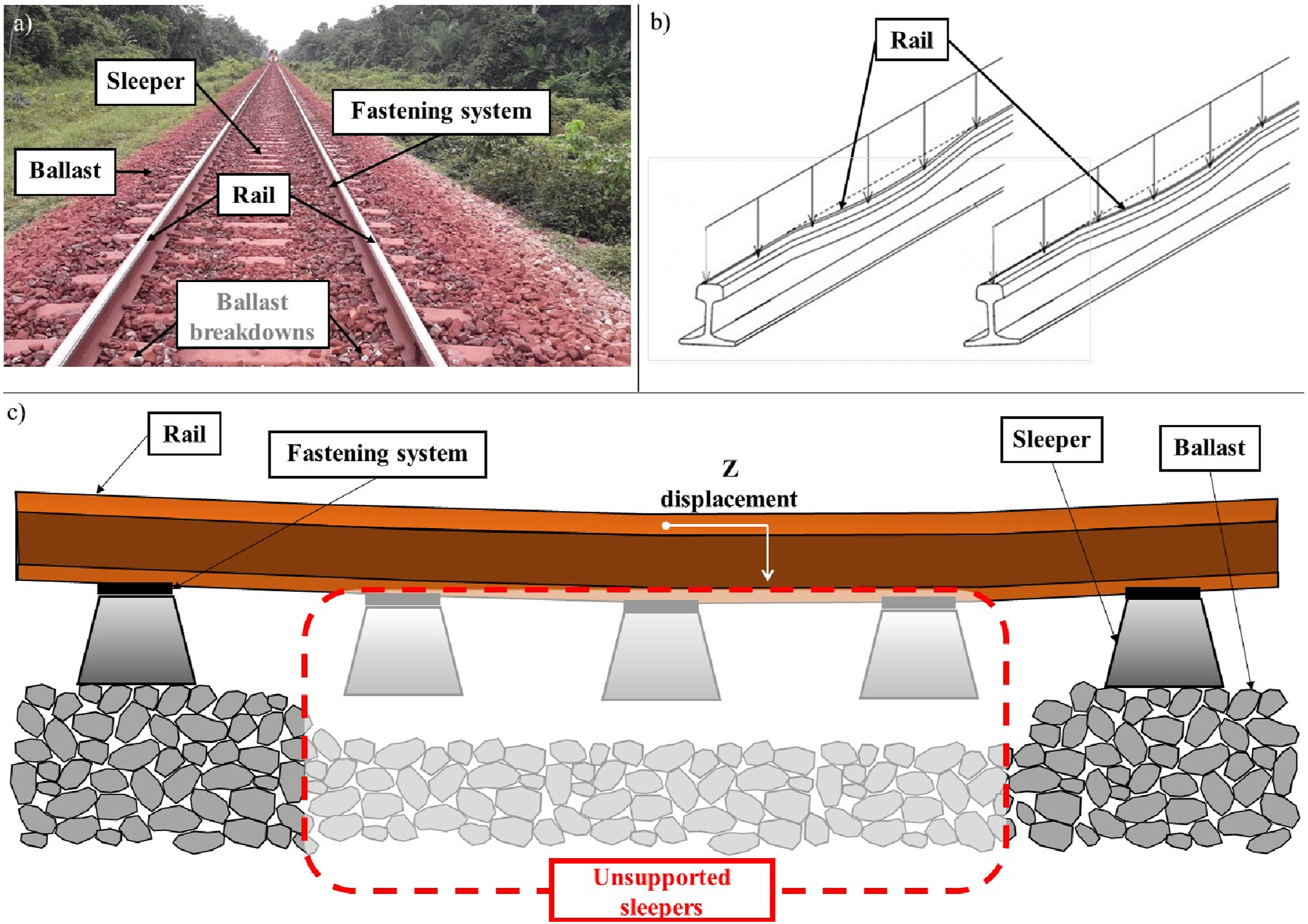
In the past and recent years, a vast number of researchers have investigated the track settlements and have proposed different approaches to predict the track geometrical VLL, mostly focusing on ballast settlement.2,24 Thom and Oakley, 7 Dahlberg, 25 and Grossoni et al. 26 carried out an excellent critical review revealing that there was not a common proceed among study conditions and, hence, among their results. Besides, to a large extent the methods indicated a dependency only on the number of cyclic loadings without taking into account any different operational, vehicle and track conditions. Trying to address the research gaps identified, Melo et al. 2 proposed a new numerical approach considering the railway dynamics conditions. However, the novelty suggested by Melo et al. 2 does not contemplate the effect of US on VLL.
Based on an extended literature review, it has been observed that no other researchers have studied the dynamic effect of US on track settlement, particularly on VLL under cyclic loadings, considering different operational conditions and elasto-plastic behaviour of track components. Mainly research discuss about dynamic responses of traditional US track (the ballast is removed beneath the sleepers) under monocyclic loading. In the past, Grassie and Cox 27 examined experimentally that on traditional US track, the dynamic wheel-rail contact force can be up 80% higher than on well supported track for monotonic loading. SUPERTRACK 28 performed a numerical modelling of railway track introducing gaps of 0.5 mm and 1 mm under three cyclic loadings and ballast plastic behaviour indicating that the sleeper-ballast contact force increases by 70% in the rail with a gap of 1 mm, similarly to the numerical study reported by Lundqvist and Dahlberg. 29 Zhang et al. 30 also studied the effect of US on the normal load of wheel-rail through a numerical simulation and their results show that the gaps have a huge response on that force as the fluctuating amplitude increases for a categorical number of US when the train velocity increases, particularly when the number of traditional US reached 5 or 6, which meant that the wavelength of the fluctuation depends on the excited resonant frequencies of the vehicle-track system. Bezin et al. 31 studied the cant deficiency effect of rail on the railway tracks with US by using numerical modelling showing that the presence of US increases the ratio (lateral/vertical force ratio) by 3%–8%. Zhu et al., 23 Zakeri et al., 32 Zhang et al., 33 Mosayebi et al., 34 and Dai et al. 35 also performed numerical simulations suggesting that the train velocity, the gap range, and the number of US primarily impose the magnitude of impact load, which is significant at high speed, whereas such impact at low speed is insignificant. Zhu et al. 12 investigated the effect of traditional US on the track dynamic characteristics by experiments indicating that since the US leads to a discontinuous and irregular track support, the wheel-rail dynamic interaction is excited being increased as the number of US is increased, or the train velocity is raised.
Recently, some researchers have worked on numerical modelling and experiments, however, despite of interesting findings – similarly to the previous studies, none of them presents any findings regarding the effect of US on VLL under cyclic loadings. The studies mostly continue to focus on monotonic loading and elastic behaviour of the track components. Ienaga et al. 36 carried out numerical simulation and experiments under low-speed range to investigate the effects of traditional US identifying an increase in rail displacement when the vehicle passes over the section with reduced track support stiffness. Sadeghi et al. 37 also researched the response of traditional US using an improved 3D numerical model and experiments indicating that an increase in the gap size (0.4 mm) results in intensification of the sleeper-ballast contact forces (25%) in the single US and that any increase of the gap of more than 0.4 mm causes negligible changes in the sleeper responses (5%). Sysyn et al. 38 carried out experimental and numerical investigation to study the dynamic interaction between the wheel and the rail with US showing that there exists a critical gap size around 2.5 mm for four US, which causes the largest force variation. Azizi et al., 11 Azizi et al., 39 and Azizi et al. 40 also investigated numerically and experimentally the response of train velocity in displacement of a ballasted railway track with traditional US finding that the velocity of the vehicle on the track displacement with less than 4 fully US has no effect, but by increasing the number of US, the effect of increasing velocity is considerable. Sadegui et al. 41 and Sadegui et al. 42 have also studied experimentally the effects of particle gradations on cyclic behaviour of ballast contaminated with sand and reinforced with geogrid, respectively. They have concluded that it is possible to predict ballast settlement taking into consideration ballast gradation, sand dosages and geogrid technique.
Sresakoolchai and Kaewunruen 16 proposed an innovative prognostic to detect and identify severities of US using machine learning based on a verified numerical simulation with existing field measurements. Differently from the others, Augustin et al. 15 investigated numerically and experimentally the influence of inaccurately positioned sleepers on track settlement under cyclic loadings testing on the ballast a cross-shaped footing made of concrete. They identified without distinguishing that badly placed sleepers significantly influence the evolution of track vertical displacements.
In general, as described above, no other studies provide an accurate investigation of the effect of US on railway track VLL in a long-term behaviour. On this ground, to address the knowledge gap identified, this study proposes the development of a novel improved numerical method to predict track geometrical VLL considering not only the railway dynamic conditions but also the response of US under cyclic loadings.
In this study, a nonlinear numerical modelling has been developed to predict vehicle-track interactions validated by field data. Analytical methods are also applied iteratively to identify an innovative function factor outlining the effect of US on VLL under heavy-haul cyclic loadings. Therefore, a long-term performance of a ballasted railway track can be evaluated to determine parametric responses of US on the track geometrical VLL. This can support the development of an efficient practical maintenance guideline recommending US configurations for a minimum effect on VLL.
Methodology
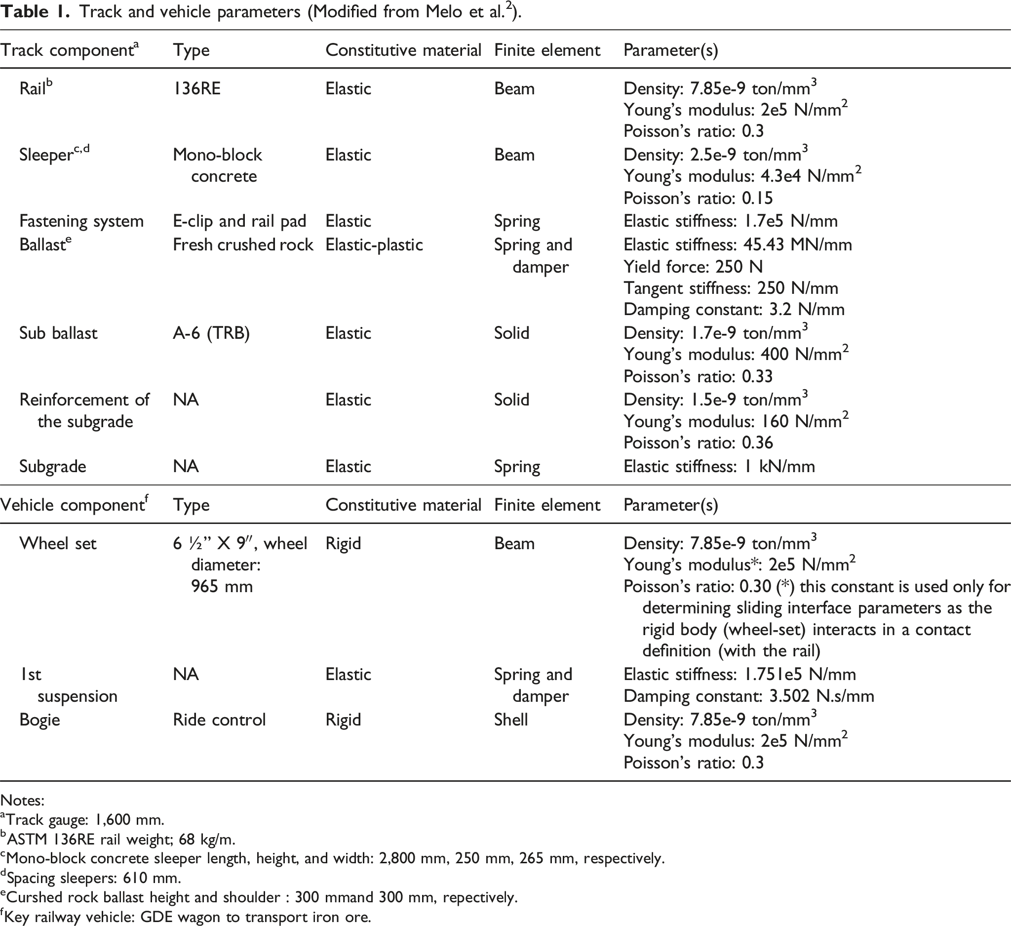
Based on a typical heavy-haul railway track and vehicle components illustrated in Figures 2 and 3 and their characteristics described on Table 1, the model has been established in 3D on LS-Dyna, for modelling the 25-meter straight track and two adjacent bogies (greatest load demand configuration) of a typical wagon. The nonlinear numerical models are simulated using an explicit finite element method as it considers the state of the system (the mass matrix) to calculate each time-step independently of the number of contact points and the complexity of contact circumstances. Its time-step is defined by the smallest element in the model. Additionally, the explicit method permits to control the time-step by including the concept of “mass scaling,” which is particularly useful to directly increases the time-step without affecting the outcome. The model is performed by employing both linear elastic and elasto-plastic constitutive law of the materials to study the effect of US on the VLL under cyclic loadings. This nonlinear model applies moving mass loads to represent the vehicles, which travel in loop along a smooth track (perfect track geometry) based on Melo et al.
2
’s study. The same vehicles travel in loop along a track with different set of US to identify their impact on track geometrical VLL over time. To investigate the dynamic effect of a heavy-haul railway vehicle, the two adjacent bogies can represent the greatest load solicitation because of superposition that the wheel loads cause into the railway track. Furthermore, as usual in many multi-body simulation software, the rigid-body depictions (e.g., mass, moment of inertia, and position of centre of gravity) of the bogies, and the wheel-sets are generally applied; spring and damper elements (suspension elements) are adopted to couple the wheel-set and the bogies. The wheel-set is modelled as a rigid beam with a small contact area. To model the bogie of that typical wagon, it is adopted shell element (Melo et al. 2024).
43
To perform the designed model, a powerful and fast computing facility has been used through the BlueBEAR platform (BB). Ordinary railway vehicles (wagons): two iron ore wagons (top), and in details (bottom), the two adjacent bogies (greatest load demand) configuration and its components (Modified from Melo et al.
2
). Track and vehicle parameters (Modified from Melo et al.
2
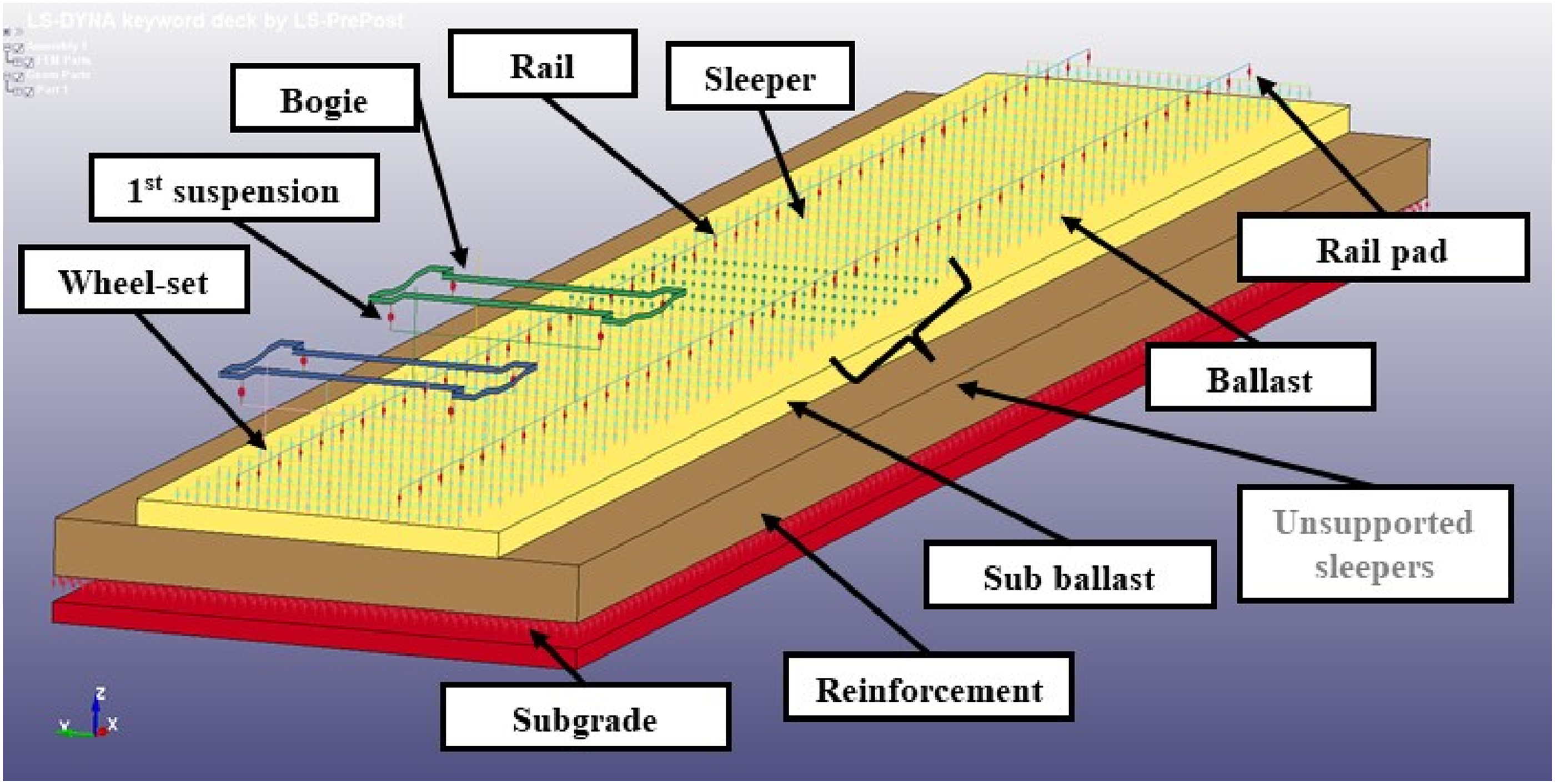
). Notes: aTrack gauge: 1,600 mm. bASTM 136RE rail weight; 68 kg/m. cMono-block concrete sleeper length, height, and width: 2,800 mm, 250 mm, 265 mm, respectively. dSpacing sleepers: 610 mm. eCurshed rock ballast height and shoulder : 300 mmand 300 mm, repectively. Key railway vehicle: GDE wagon to transport iron ore. Railway track and vehicle model on LS-Dyna FE software (in detail, smooth and US track segments).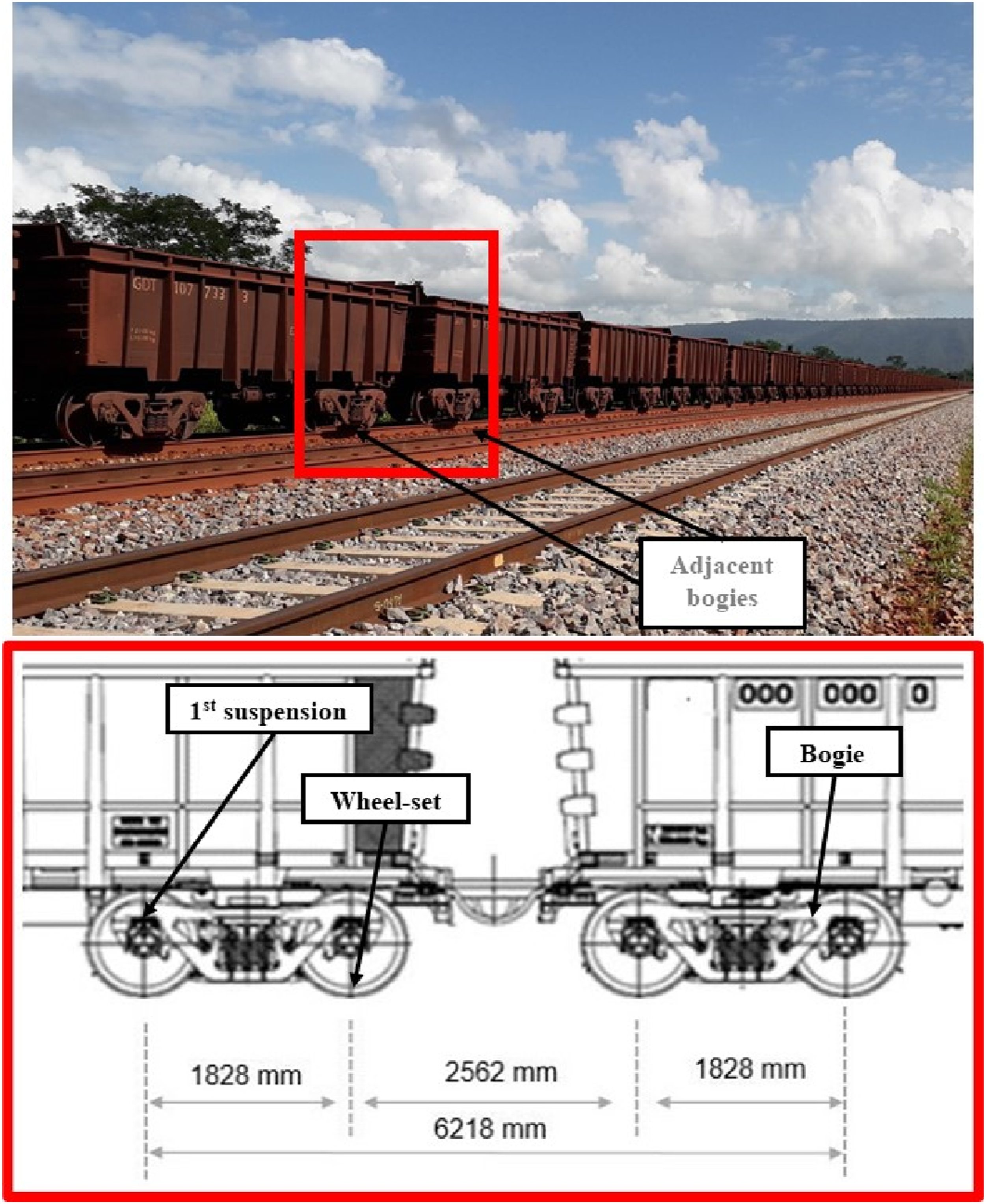
In order to modelling the referenced ballasted track, it has been considered that the primary source of VLL is the ballast settlement,
2
which means that there is a substantially robust set of subgrade.
8
Besides, as the ballast is a granular layer subjected to an extreme stress under repeated loadings, its settlement can be caused by particle rearrangement and/or breakage implying necessarily vertical cumulative deformation.
44
According to Melo et al.,
2
this situation can be approximately characterized on FE model by an elasto-plastic discrete (spring and damper) element with isotropic hardening, in which the applied load is split into a sequence of accretions (repeated loadings). Sub ballast and reinforcement of subgrade are modelled as solid elements with 100-mm-mesh-size. Additionally, in an US track section, the gap is modelled as a non-linear function underpinned by displacements events. To guarantee that the sleepers can transfer the load to the ballast properly, the “gap” is defined as a compressive displacement which the discrete element sustains before beginning the force-displacement relation given by the load curve.45,46 As soon as the sleeper is loaded and moves towards the ballast, a maximum vertical rail displacement (MaxVRD) is achieved. However, it is important to highlight that no force acts on ballast underneath the sleepers until a predesigned gap is ceased, which reduces the ballast stiffness to a lower level.
33
For modelling the traditional US, the discrete elements beneath the sleepers are eliminated, which means that there is not any transfer load from the sleepers to the ballast directly beneath the sleepers.12,47 In this condition, the whole load is transferred from the rail to the adjacent supported sleepers, and consequently to the ballast beneath them. The validation of this model will be presented in “Results and Discussion” section. In this study, which focuses on low to medium frequencies and heavy-haul axle loads, the sleeper is modelled as a beam element due its higher computational efficiency and approachable results if compared to a solid element, as pointed out by Lundqvist and Dahlberg,
29
Sysyn et al.,
38
and Xu and Lu.
48
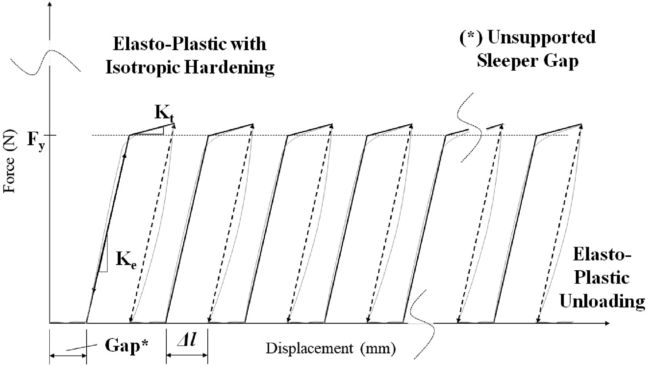
The non-linear characteristics of the model are shown in Figure 4. The force-displacement relationship during repeated loading can be written as: Loading and unloading force-displacement curves for considering the ballast elasto-plastic behaviour and US.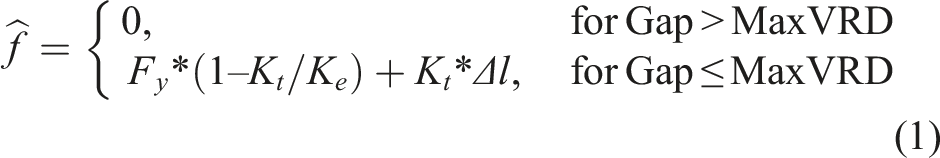
At first, the maximum values of vertical rail displacement (MaxVRD) are numerically generated by the nonlinear FE model under repeated loadings, short-term behaviour and track conditions, the later specifically related to the condition of sleeper support. The outcomes of numerical simulation are regressed by a Nepierian logarithmic (LN) function to provide an analytical estimation of the MaxVRD for the real repeated loadings of the track with supported sleepers as proposed by Melo et al.
2
This equation may be written as:
Following this initial investigation, the differences between each 4-cycle loads into the long-term performance of the MaxVRD regressed function (Equation (2)) for smooth track are determined. The outcomes suggest the first term of equation (2) as the track geometrical VLL, which also can be written as
2
:

Equations (3) provides an estimation of VLL (smooth track) for the real repeated loadings.
2
In turn, the MaxVRD values curve is also numerically generated considering the effect of the US on vertical rail displacement in a short-term behaviour. The ratio difference between the MaxVRD for US and the MaxVRD for smooth track, under the same technical and operational conditions, is also calculated. However, the analytical ratios are initially unstable (N <200 cycles) due the different displacements when the railway vehicles move forward or backward as well as the large initial ballast settlement in response to the gap underneath the sleeper. Therefore, this study proposes to take into account the ratio curve from 200 cycles on, designating this as a more stable phase that represents properly the response of US on VLL over time. The ratio curve indicates how much both the number of US and the gap beneath sleepers influence the VLL under cyclic loadings. It can be regressed by a Power function to provide an analytical estimation of the response of US on VLL. This equation can be written as:

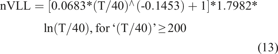
In order to validate the effect of US on VLL (Equation (5)), the wheel-rail contact force of the model is also compared to the field experiments carried out by Ref. 11 and 39-40 at the similar set-up considering traditional US. This stage is related to the model validation. Examining that the US can affect the VLL over time, it is possible to improve Equation (2) multiplying it by ‘(1 + Equation (5))’. Thus, the new VLL (nVLL) can consider the effect of US. It may be written as: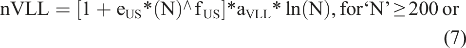
From the previous stages, this study continues to carry out numerical simulations varying three parameters: number of US (1-5 sleepers), gap beneath sleepers (1-5 mm), and axle load (20, 30 and 40 tons). Train velocity and other track and vehicles parameters are kept constant. Additionally, the dependent variables are identified and the final graphics to predict the effect of US on the track geometrical VLL are proposed. Furthermore, the performance and the analysis of the long-term behaviour of the model are presented. The methodology to develop this research is indicated in Figure 5. Methodology flowchart.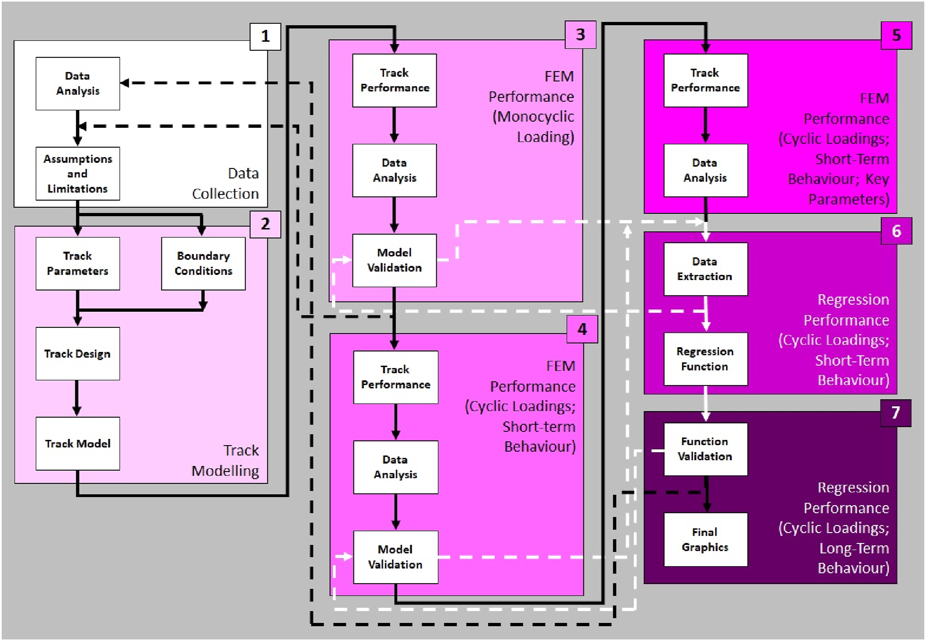
Results and discussion
To verify whether the numerical model can provide reliable insight into the effect of US on track geometrical VLL, first the validity of the FEM results regarding the wheel-rail contacts forces is studied considering monotonic loading, elastic behaviour of components, and traditional US track. It is verified the FEM model outcomes with the field experiments carried out by Azizi et al.,
11
under similar operational and track parameters. Azizi et al.
11
’s track experiments were undertaken under 21-ton axle load and 70-km/h train velocity. To perform the effect of traditional US, the ballast beneath the sleeper is removed. Figure 6 shows a comparison of wheel-rail contact forces provided by the numerical (FEM) and the field investigations. From that Figure, the maximum difference is 6% approximately at 5 US track. Therefore, the outcome from the developed model gives a reasonable match with the measured data in the field tests. Comparison of (a) wheel-rail contacts forces and (b) dynamic ratio (dynamic force divide by static one) between the numerical model (FEM) and the field experiments carried by Azizi et al.,
11
under similar operational conditions (21-ton axle load, 70-km/h train velocity, and traditional US condition).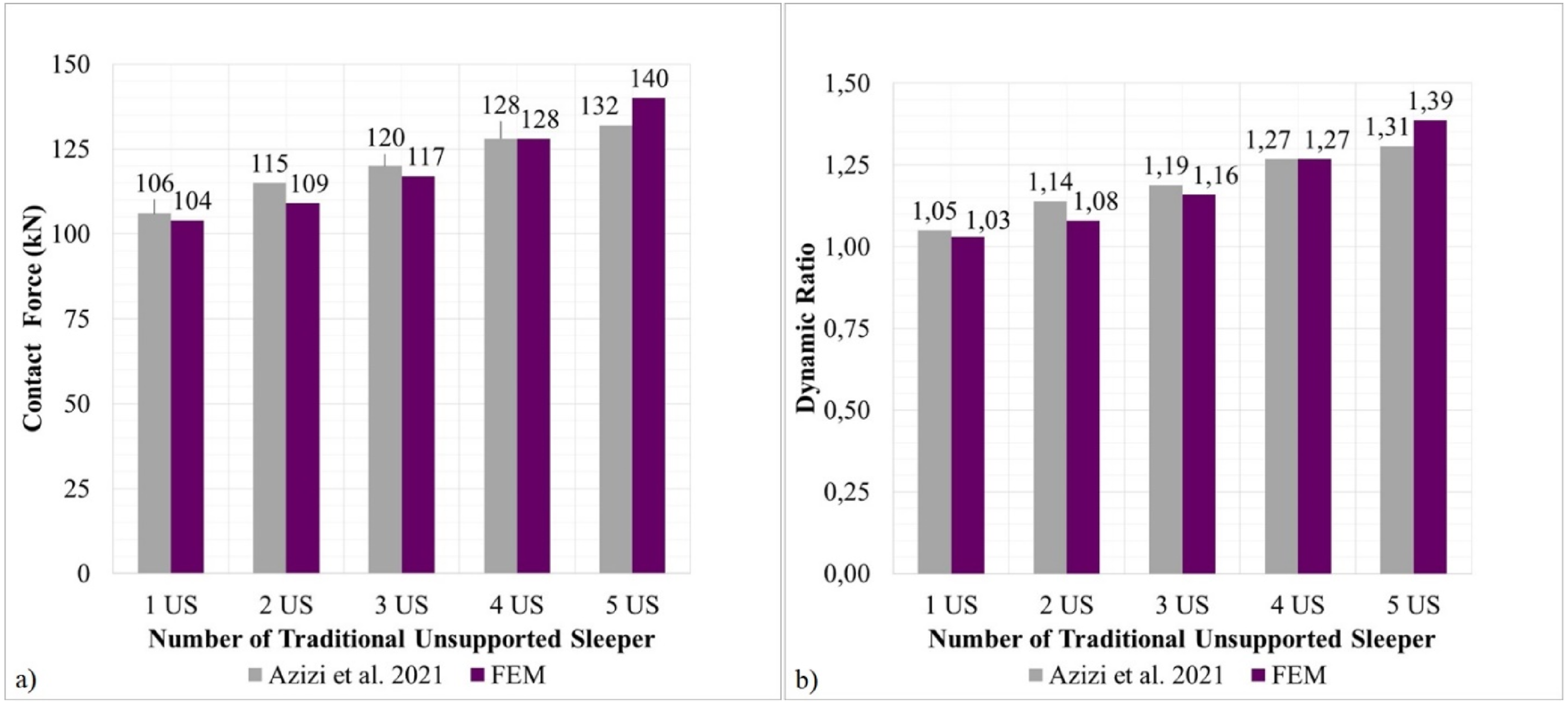
From the proposed methodology, the track model is developed based on Melo et al.
2
’s study (smooth track). The operational parameters (20, 30 and 40-ton axle loads, and 70-km/h train velocity) and the US track conditions (1-5 US with 1-5-mm gap) are applied, and the models are performed on BB. Figure 7 illustrates the model performed using LS-Dyna FE package. Track model performed under 40-tonnes axle load and 70-km/h train velocity (in details, the rail FE node displacement, and the indication of the 5 US sleepers with 5-mm gap).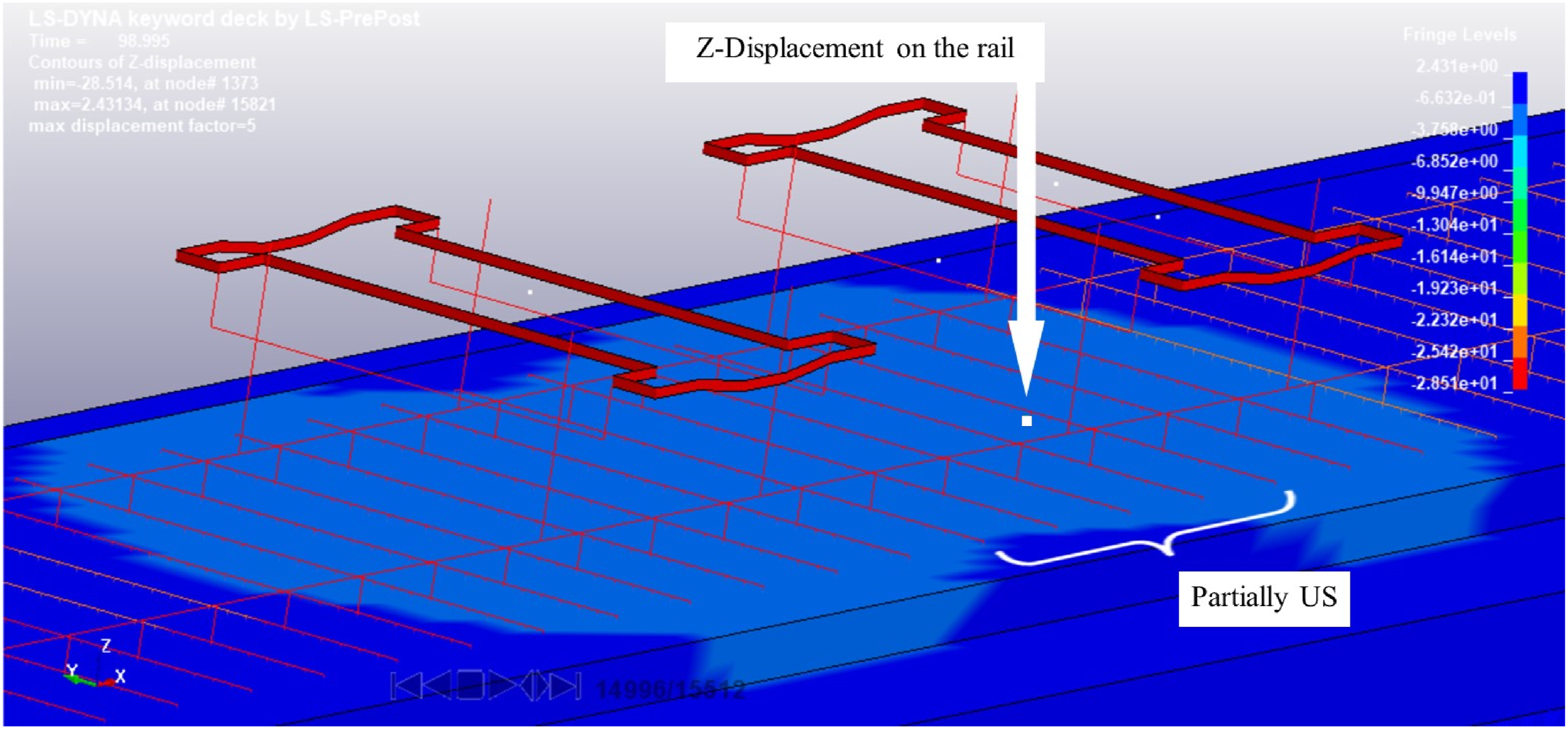
The vertical rail displacements (VRD) are numerically generated by the sum of elasto-plastic displacements on wheel-rail contact in vertical direction (‘Z-Displacement’ in Figure 7) for each repeated load. The slope of those displacements represents how faster and deeper the track loses its vertical profile.
2
The MaxVRD after each 4 repeated loads are identified to both track conditions: supported and US tracks. During that stage, the MaxVRD values, under repeated loadings (short-term), are regressed by a LN function to provide an estimation of the MaxVRD regression function for a smooth track. The coefficient of determination, denoted R2, of the LN expression under 40-ton axle load and 70-km/h train velocity is 0.9730, which indicates a good accuracy. The results for this step can be written as follows: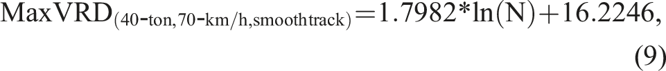
As suggested by Melo et al.,
2
the differences between each 4-repeated loads for a long-term performance of the MaxVRD LN function are calculated. The outcome indicates that the first term of equation (9) is related to the VLL. Thus, the track geometrical VLL for those railway operation conditions, and smooth track may be written as:

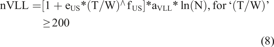
Following on the proposed methodology, the US gap is modelled in an US track as a non-linear element indicating that no force acts until the clearance is ceased. Similar to that smooth track, the MaxVRD curve is identified for the US track. The ratio differences between the MaxVRD for both tracks (in each 4-cycle loads are calculated, and a new curve is determined. The ratio differences are regressed by a Power function from 200 cycles (stable phase) to define the function factor effect of US for the uneven track. The coefficient of determination (R2) of the Power equation is 0.9707, which also indicates a good accuracy. The effect of US represented by ‘μ’ function shows that the values of the eUS and fUS are 0.0683 and −0.1453, respectively. The first coefficient (eUS) expresses the initial effect of US, whereas the second constant (fUS) reveals the rate of ‘μ’. That new curve expresses the response of US on MaxVRD and, consequently, on VLL over time. The non-linear characteristics of the performed models and the ratio differences between their MaxVRD are shown in Figure 8. Therefore, the new VLL (nVLL) may be updated as: Short-term behaviour of (a) VRD and (b) MaxVRD (each 4-cycle loads) on FEM under 40-ton axle load, 70-km/h train velocity, 5 US with 5-mm gap beneath sleepers (in details, bottom: the ratio differences graphic between MaxVRD for uneven and smooth tracks, respectively).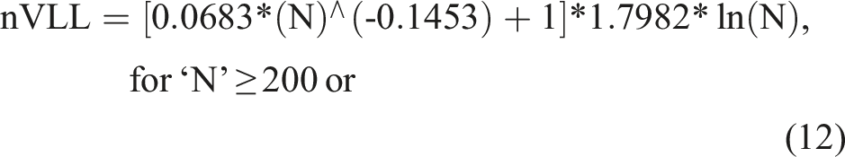
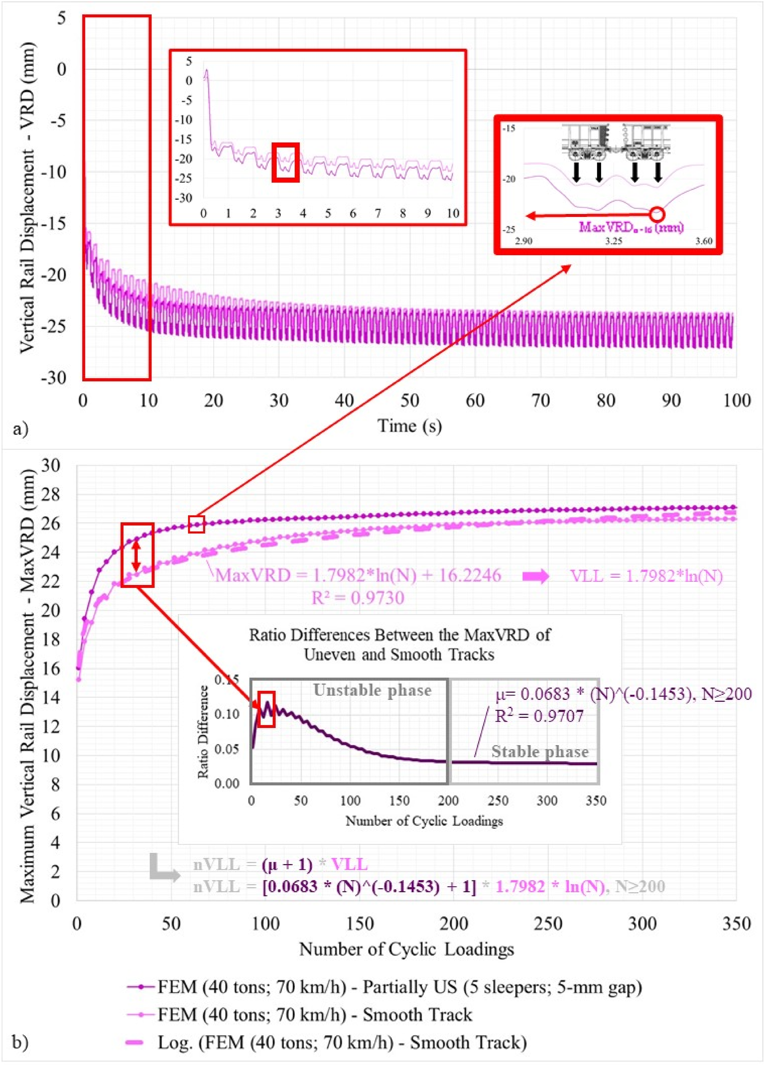
From Figure 8(b), it can be observed that the difference between the MaxVRD curves suggests a clear response of the US. Initially, during the first cycles, the difference rises sharply in function of the existing gap underneath the sleepers, which indicates that the wheel-rail contacts forces for the uneven track overcomes substantially the smooth track due the variation of dynamic forces (impact loadings) generated by the US. These dynamic loadings are transferred from the rails through rail pads and sleepers to damage the ballast beneath the sleepers for each load cycle. Therefore, the ballast under those extreme impact loadings starts to settle substantially causing the losses of vertical profile on the top of the rails. It attests the effect observed in Zhang et al. 30 After 25 cycles, the difference between them startling decreases suggesting that the effect of US commences to be reduced as the rail displacement becomes larger than the gap. It can be noted that only after 200 cycles, the difference between the MaxVRD curves assumes a stable behaviour indicating a constant rate of influence related to the existing US condition.
Equation (12) presents the accumulation of the nVLL for the real repeated loadings taking into consideration the effect of US (uneven track). The VLL at both 10 thousand and 1 million cycles are approximately 16.5 mm and 24.8 mm, whereas the nVLL are 16.9 mm and 25.1 mm, meaning that the US condition degrades the vertical profile in 1.8% and 0.9%, respectively. It indicates that the dynamic influence of US reduces over time as deeper as the sleepers moves towards the ground due mainly the ballast settlement, which overcomes considerably the gap beneath sleepers. This observation is also identified in Augustin et al. 15 when they explain the influence of poorly installed sleepers on the evolution of VLL.
In order to extend the investigation of the effect of US (μ) on VLL, different axel loads, and US conditions are applied on FEM under similar train velocity, vehicle characteristics, and track parameters as the previous simulation. Figure 9 depicts the comparisons of US function factor coefficients (eUS and fUS) for 20, 30 and 40-ton axle loads, 70-km/h train velocity and the ranges of 1 to 5 US with 1 to 5-mm clearance underneath the sleepers. For the railway tracks dominated by 20-ton axle load (light railway), both eUS and fUS present a bell-shaped behaviour reaching the maximum and the minimum values, respectively, at 3-mm gap for 4 US. It does not mean necessarily the worst scenery; however, it indicates a critical configuration, which reflects the natural frequency of the ballasted railway track that is influenced not only by the 20-ton axle load but also by the track configuration (existing US). Comparisons of μ′s coefficients (eUS and fUS) for (a) 20, (b) 30 and (c) 40-ton axle loads, 70-km/h train velocity and the ranges of 1 to 5 US with 1 to 5-mm clearance underneath the sleepers.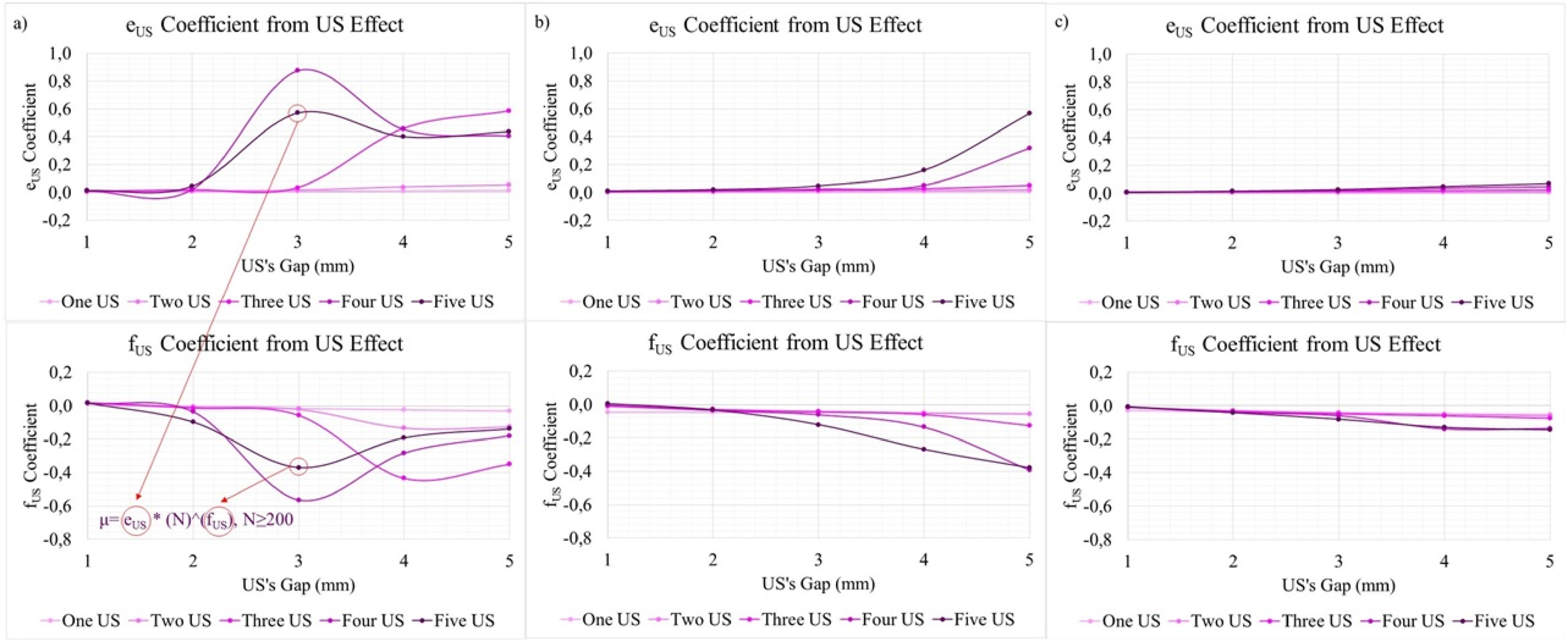
On the other hand, if the axle load increases to 30 and 40 tons, the US function factor coefficients increase or decrease slightly until 3-mm gap for 1-5 US indicating that these configurations do not significantly alter the VLL. In turn, at 4-mm gap on and for 4-5 US, the effect of US for 30-ton axle load (heavy haul railway) increases sharply implying that track configuration might be their critical one. Besides, it is noted that the coefficients for 40-ton axle (extreme heavy haul railway) raise or reduce marginally at 4-mm gap on and 4-5 US suggesting that the vertical rail displacement for 40-ton axle load is much larger than the gaps beneath the sleepers.
The effect of US on track geometrical VLL can also be discussed looking at the long-term performance, as illustrated in Figure 10. The differences (%) between the VLL for US track (uneven) and supported sleepers track (smooth) are calculated based on Equations (3) and (12) at 3 million cycles (or 60 MGT, which roughly represents the amount of 4 months of traffic in a typical heavy haul railway) for the same parameters described above. The trend of VLL degradation is not straightforward. It is observed, however, that the worst configuration for 20-ton axle load is at 5 US with 5-mm gap (5,51%). In turn, for 30 and 40-ton axle loads the unfavorable scenery is at 5 US with 2-mm gap (1.23% and 0,89%, respectively). Despite of this indicating that the axle load affects considerably the VLL, the US condition plays an important role to accelerate it. However, it is important to highlight that if the initial gap increases, for example, the effect changes and it can impact considerably on VLL. As the US is commonly found in major locations, an acceptable configuration for the gap between the sleeper and the ballast can be specified for a minimum effect on VLL (thresholds) and, therefore, contribute as a practical guideline to support the construction and maintenance activities in a ballasted railway track. The graphical (a-c) and numerical (d) differences in percentage (%) between VLL at 3 million cycles (MGT) for US (uneven) and supported sleepers (smooth) tracks under (a) 20, (b) 30, and (c) 40-ton axle loads, 70-km/h train velocity and the ranges of 1 to 5 US with 1 to 5-mm clearance underneath the sleepers.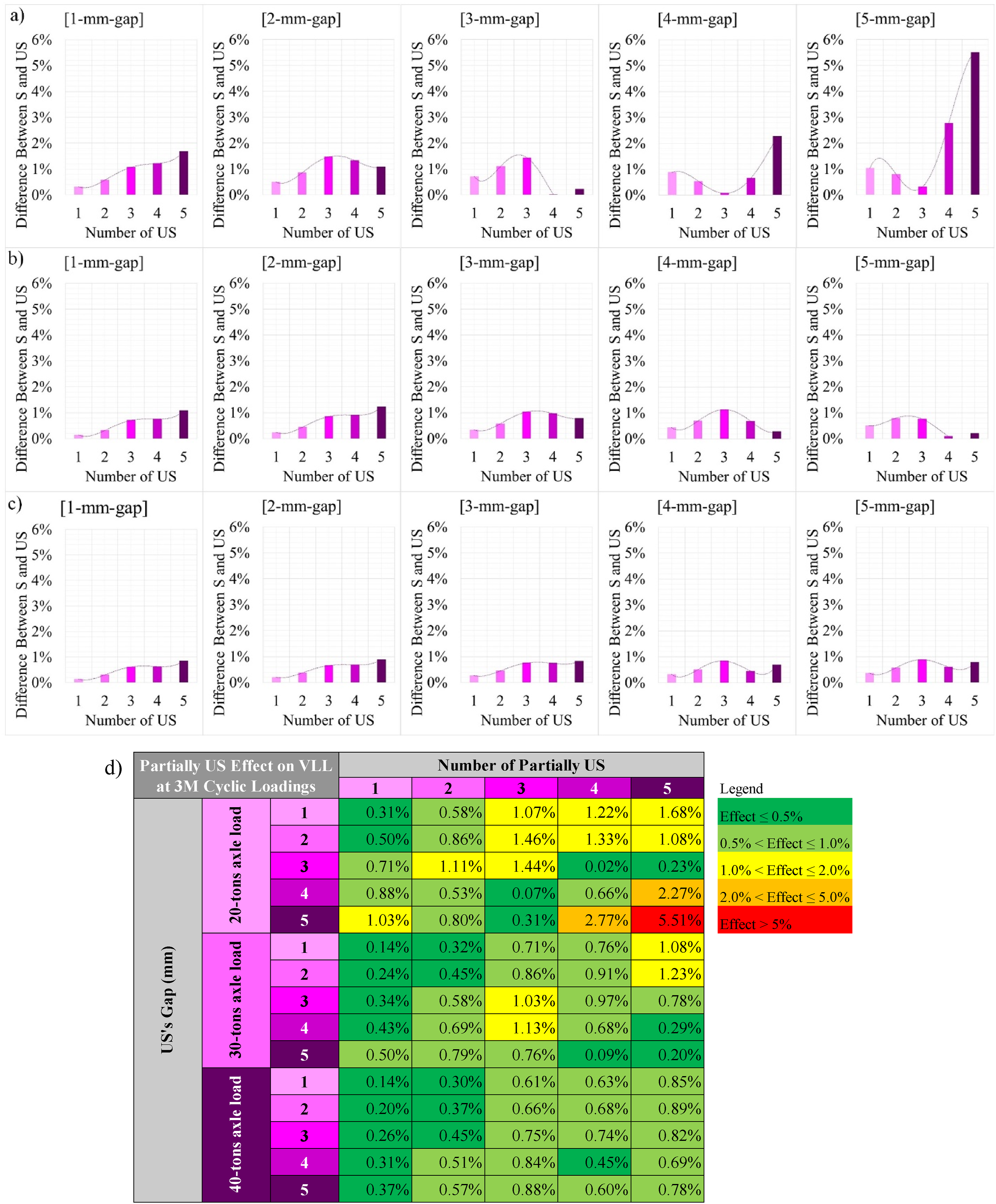
Conclusions
This study presents new insights into the effect of US on a ballasted railway track geometrical degradation after construction or maintenance activities. To investigate this phenomenon, a numerical study has been developed and validated focusing on the track geometrical VLL under cyclic loadings.
For an uneven track, the investigation indicates that there is a noticeable influence of US on VLL. However, the influence is reduced as much as the axle load increases meaning that the dynamic wheel-rail contact force (impact loading) for a heavy haul railway (30 and 40-ton axle loads), for example, can lead the whole ballasted track settlement over time. On the other hand, for a light railway (20-ton axle load), if the vertical rail displacement is closer to the gap beneath the sleeper, the increase of impact loading is more influenced by the US conditions implying a relative and variable increment of vertical rail displacement.
Even though the insights demonstrate that the axle load effect is more pronounced, the US condition plays an important role to contribute further on track geometrical VLL. As the US can be observed in railway tracks, the fact that it exists must be known to the track engineers and the acceptable configuration should be specified for a minimum effect on VLL (thresholds). Therefore, given that this novel improved method can accurately predict the effect of US on the track geometrical VLL considering different railway operational conditions (and configurations), their findings contribute to obtain new insights into track geometry degradation, and enhance the development of new practical maintenance and construction guidelines.
Footnotes
Acknowledgements
The first author gratefully appreciates the Brazilian National Council for Scientific and Technological Development (CNPq), Brazil, Project No. 200359/2018-5, for his PhD scholarship. We are sincerely grateful to the European Commission for the financial sponsorship of the H2020-RISE Project No. 691135 “RISEN: Rail Infrastructure Systems Engineering Network,” which enables a global research network that tackles the grand challenge of railway infrastructure resilience and advanced sensing in extreme environments. 49
Declaration of conflicting interests
The author(s) declared no potential conflicts of interest with respect to the research, authorship, and/or publication of this article.
Funding
The author(s) disclosed receipt of the following financial support for the research, authorship, and/or publication of this article: This project has received funding from the European Union’s Horizon 2020 Research and Innovation Programme Under Grant Agreement No. 691135 (H2020-RISE Project No. 691135 “RISEN: Rail Infrastructure Systems Engineering Network”). The APC is kindly sponsored by the University of Birmingham Library’s Open Access Fund.