
Abstract
The interface damage is considered to be one of the main diseases of China Railway Track System (CRTS) Ⅱ slab ballastless track, which will affect the long-term performance of the track structure and safety operation of high-speed trains. This study aims to reveal the interface damage mechanism between the track slab and the cement asphalt (CA) mortar layer of CRTS Ⅱ slab ballastless track, under different combinations of temperature actions and initial gap damage. A three-dimensional finite element model of CRTS Ⅱ slab ballastless track was established, in which a cohesive constitutive model was incorporated to simulate the interaction behavior of the interface. The interface damage evolution under different temperature actions and initial gap damage was analyzed. The analysis results show that: (1) Overall temperature has a more obvious effect on interface damage compared with temperature gradient, and the greater the overall temperature drops, the lower the decrease of interface damage will be; (2) When initial gap damage occur at the slab end, the growth rate of interface damage under temperature gradient is greater than that under overall temperature; The interface will begin to delaminate when the overall temperature drop reaches −50°C and the gap length becomes greater than one fastener spacing; and (3) When initial gap damage occur at the slab edge, the influence of overall temperature on interface damage is greater than that of temperature gradient; The interface gap damage reaches level II (according to TG/GW 115-2012) at the slab edge under the combination of −50°C and −50°C/m, while the slab center interface is unlikely to be damaged under negative temperature.
Keywords
Introduction
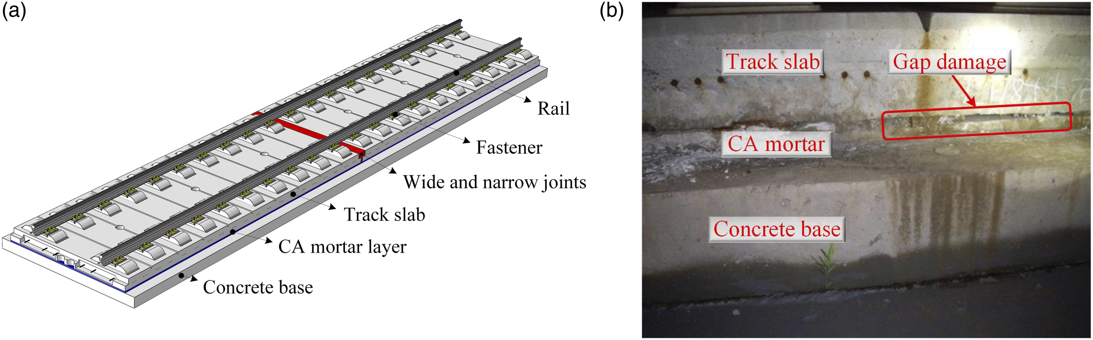
Compared with traditional ballast track structures, the ballastless track structure has the advantages of high smoothness, excellent durability and low maintenance, which becomes the preferred structural form in high-speed railway construction.1–3 CRTS II slab ballastless track is one of the most widely used ballastless track structures in China, which consists of rails, fasteners, track slabs, wide-narrow joints, CA mortar layer and concrete base, as shown Figure 1(a). Field investigations found that interface gap damage mainly occurred at the interface between the track slab and CA mortar layer,
4
as shown in Figure 1(b). This may lie in: the construction quality of the interface between the track slab and CA mortar is difficult to control, and it is greatly affected by adverse environmental factors such as temperature, trainload, and water. The interface gap damage will seriously affect the long-term service performance of track structure and safety operation of high-speed trains.5,6 CRTS Ⅱ slab ballastless track: (a) Illustration, (b) Interface gap damage between track slab and CA mortar layer.
4
Many researches have been carried out to investigate the generation and development law of the gap damage between track slab and CA mortar layer. Temperature action is found to have a significant impact on the interface damage of CRTS II slab ballastless track,7,8 which can be divided into overall temperature and temperature gradient.9–11 Under the action of overall temperature rise, a huge compressive force will be generated in the track slab, resulting in significant arch. deformation.12–14 The influence of temperature gradient on the vertical deformation of track structure is also obvious. 15 Under the action of positive and negative temperature gradient, the track slab exhibits arching and concave deformation, respectively.16–19 Besides the temperature actions, initial gap damage between the track slab and CA mortar layer will seriously affect the stability of track structure, which is general in practice due to the improper construction operation.20–26 Existing studies, as presented above, investigated the interface behaviour considering initial gap damage under the action of overall temperature or temperature gradient independently. In practice, however, the temperature of track structure changes with ambient temperature, 27 and it is necessary to consider the actions of overall temperature and temperature gradient simultaneously.
The objective of the present study is thus to reveal the interface damage mechanism between track slab and CA mortar layer under the combined effect of overall temperature, temperature gradient, and initial gap damage. The rest of this paper is organized as follows. Firstly, a three-dimensional finite element model (FEM) of CRTS II slab ballastless track is established, and the FEM is verified by experimental results. Then, the interface damage mechanism between CRTS II slab track and CA mortar layer is investigated, under the combined action of overall temperature, temperature gradient, and initial gap damage. Finally, concluding remarks are summarized. Literature suggests that the contributions of this study include the following points: (1) To be in consistent with the practice, in this study, the mechanism of interface damage under the combined effect of overall temperature and temperature gradient is analyzed. The development law of interface damage at different positions of the track slab, and the most unfavorable temperature combination of overall temperature and temperature gradient were determined through FEM analysis. (2) The development law of interface damage under different combinations of overall temperature, temperature gradient, and initial interface local gap damage are investigated. The results demonstrate that the track structure is in a more unfavorable stress state when initial gap damage exists at the interface.
Finite element model of CRTS Ⅱ slab ballastless track
Dimensions and materials
To study the damage mechanical behavior of the interface between track slab and CA mortar layer, a three-dimensional FEM of CRTS II slab ballastless track structural system is established by using the software ABAQUS, as shown in Figure 2. As CRTS II slab ballastless track structures are generally laid on simply supported bridges with a length of 32 m, the FEM is established with a length equal to five component track slabs, and the middle one is the focus of this study. Track slabs and the concrete base are bonded by the CA mortar layer. Track slabs are longitudinally connected with reinforcements and wide-narrow joints. According to references of [12] and [28], structural parameters and material properties of CRTS II slab track components are listed in Table 1. CRTS II slab ballastless track structural system (unit: mm). Track structure size and material properties.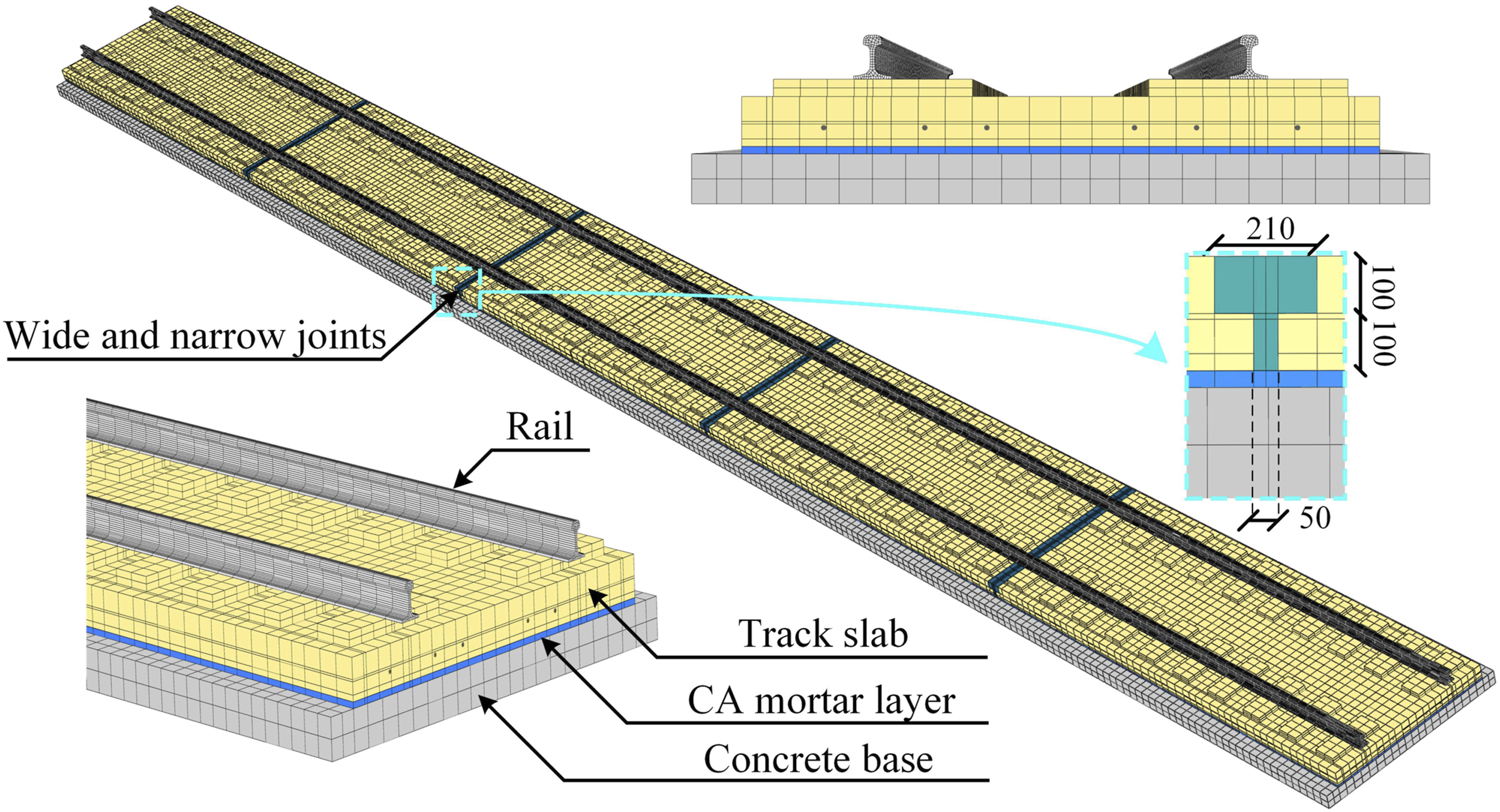
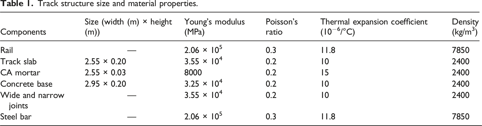
The rail, track slab, wide-narrow joints, CA mortar layer and concrete base are simulated by eight-node solid element C3D8R. The longitudinal and transverse reinforcements in the track slab are simulated by truss element T3D2. The length of the transverse reinforcement is 2.55 m and the diameter is 10 mm; and the length of the longitudinal reinforcement is 6.35 m with the diameter of 8 mm. The interaction between reinforcement and concrete is realized by the embedded model. The interface interaction between track slab and CA mortar layer is simulated by the cohesive element COH3D8. The minimum length of elements is about 2.5 mm, and the total number of elements is 230,761.
The rail and track slab are connected by WJ-8 fastener, and the fastener spacing is 0.65 m. The vertical and lateral stiffness of the fastener is 4.5 × 10⁷ N/m and 3.0 × 10⁷ N/m, respectively. The vertical and lateral damping of the fastener is 6.0 × 10⁴ N·s/m and 3.625 × 10⁴ N·s/m, respectively.
29
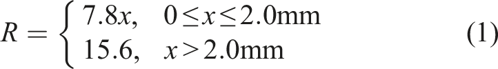
The longitudinal stiffness of the fastener is simplified as the bilinear relationship of force and displacement. When the displacement is less than 2 mm, the longitudinal force increases linearly with displacement; while when the displacement is more than 2 mm, the longitudinal force remains constant. The longitudinal force of the fastener is expressed by the equation as follows:
30
Cohesive zone model
As a non-intensity factor dominant fracture model, the cohesive zone model (CZM) is widely used in the study of interface bonding failure of composite materials.31–33 Among different types of CZMs, the bilinear CZM is most suitable for studying brittle fracture.34–39 Therefore, the bilinear model is selected to simulate the interface damage,
34
as shown in Figure 3. Bilinear cohesive zone model.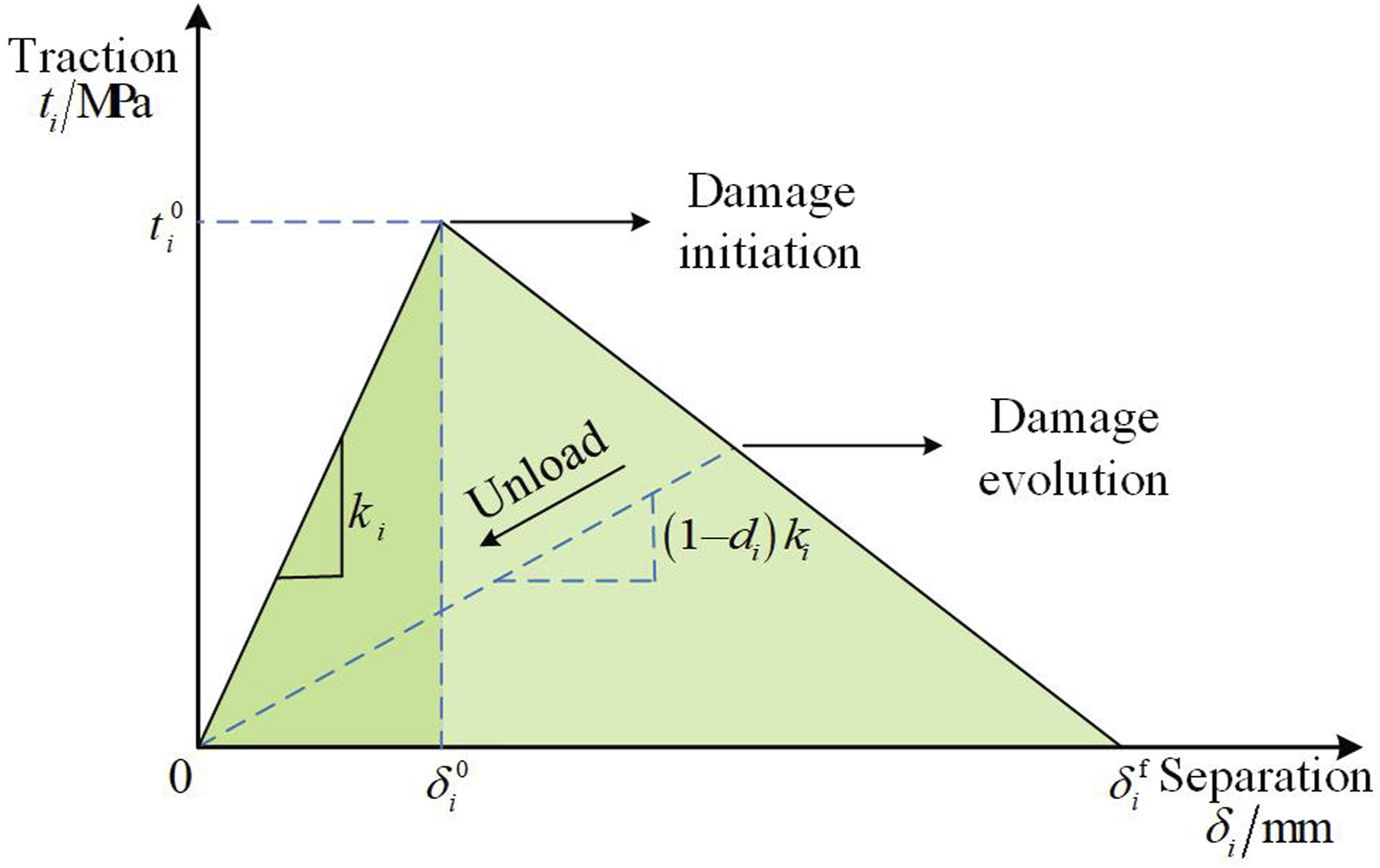
The constitutive relationship of the bilinear CZM can be expressed as: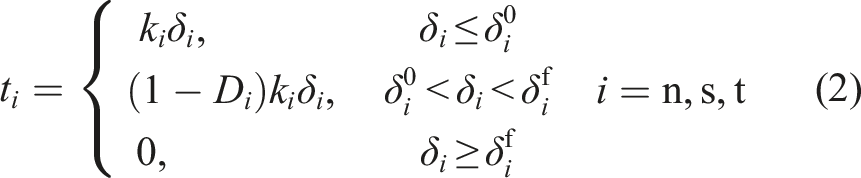
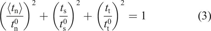
The criterion of quadratic nominal stress is used to determine the initiation condition of interface damage, which is formulated as follows:
40
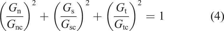
The fracture criterion of cohesive element can be expressed as:
41
The interface damage is quantitatively described by introducing the damage factor 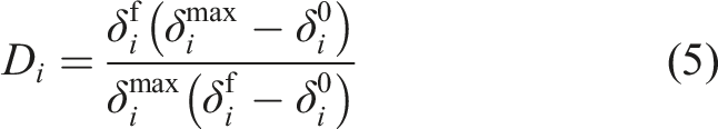
It can be observed from equation (5) that,
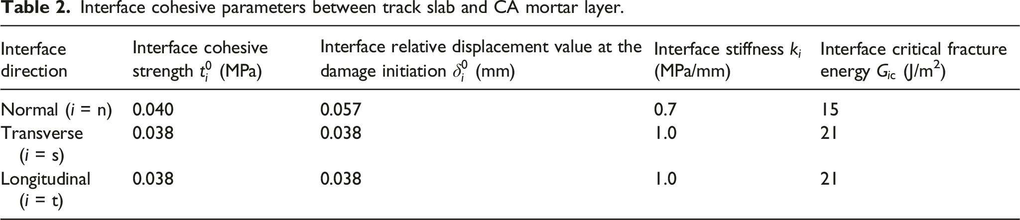
Interface cohesive parameters between track slab and CA mortar layer.
Temperature action
The temperature action is one of the most important factors affecting the mechanical behavior of CRTS II slab ballastless track, which includes overall temperature and temperature gradient. 44 The temperature action is greatly affected by the surrounding environment. Generally, the construction temperature of slab ballastless tracks is about 20°C. 12 Considering extreme environmental conditions, the maximum overall temperature rise and drop considered in this study are set to be 40°C and −50°C, respectively.45,46 Considering the possible temperature gradient limit, the range of temperature gradients is set to be [−50°C/m, 100°C/m].47,48
It should be noted that, the temperature gradient can be categorized as vertical and horizontal ones, and the vertical temperature plays a leading role in the performance of the track structure. Transverse temperature gradient will appear under non-direct sunlight conditions, while it has little effect on the interface gap damage.49,50 Therefore, only the influence of the vertical temperature gradient is considered in this study, by assuming the temperature is linearly and uniformly distributed along the vertical and horizontal directions, respectively.
Boundary condition
According to the symmetry of the longitudinal continuous structure, symmetric constraints are set at both ends of the model to reflect the longitudinal connection characteristics of the track structure.
Based on the on-site observations, almost no debonding occurs at the interface between the CA mortar layer and concrete base, and thus tie constraints are set between CA mortar layer and concrete base in the FEM. Furthermore, as a longitudinal continuous structure, the interface damage between the track slab and the wide-narrow joints is also neglected, with the corresponding interface interaction set as tie constraints.
In this study, the ballastless track is laid on the bridge and the bridge is regarded as the Winkler foundation, which is simulated as an elastic foundation model with the foundation coefficient taken as 1000 MPa/m. 51 It should be noted that, such simplification may bring in some problems when considering long-term bridge deformation and potential degradation of materials,52–55 and the impact of the bridge structure needs to be considered for such cases.
Model validation
In order to verify the accuracy of the FEM in this study, experimental data and simulation values of the interfacial adhesion between track slab and CA mortar were compared to verify the interfacial damage. Then, the deformation of track structure is verified by comparing the measured deformation data of the on-site track slab with the finite element simulation results.
Verification of interface damage
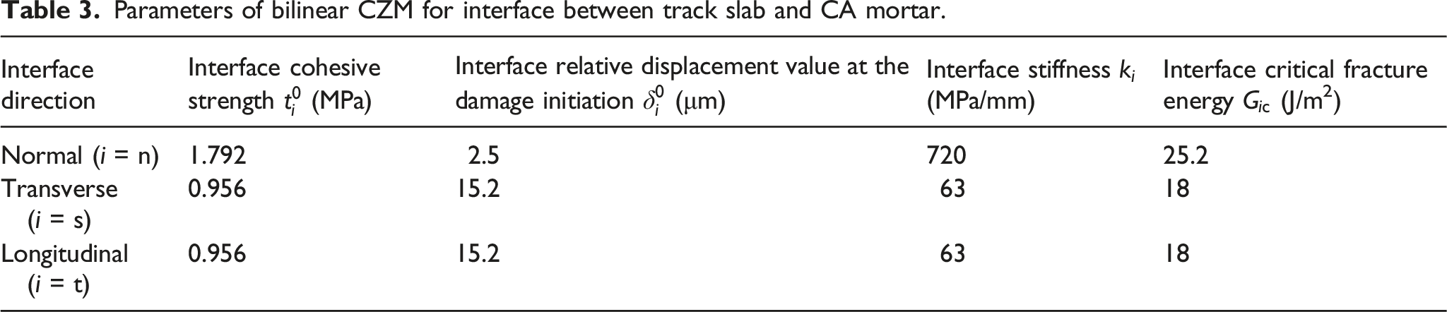
In order to illustrate the rationality of the bilinear CZM to simulate the interfacial cracking behavior between track slab and CA mortar, the splitting test and shear test in Ref. [56] were used. These experimental tests used the cubic composite specimen with the standard dimension of 150 × 150 × 150 mm3, and the dimensions of the track slab concrete and CA mortar were both 75 × 150 × 150 mm3. Two-dimensional FEMs corresponding to splitting test and shear test were established by ABAQUS, as shown in Figure 4. Track slab and CA mortar were characterized by two-dimensional solid element CPE4R, and the interface was characterized by cohesive element COH2D4. The material parameters of track slab concrete and CA mortar are shown in Table 1. The interface behavior between track slab and CA mortar is simulated using the bilinear CZM. The relevant cohesive parameters are obtained from the experimental data in Ref. [56], as shown in Table 3. Finite element model of interface bonding test (unit: mm): (a) Splitting test, (b) Shear test. Parameters of bilinear CZM for interface between track slab and CA mortar.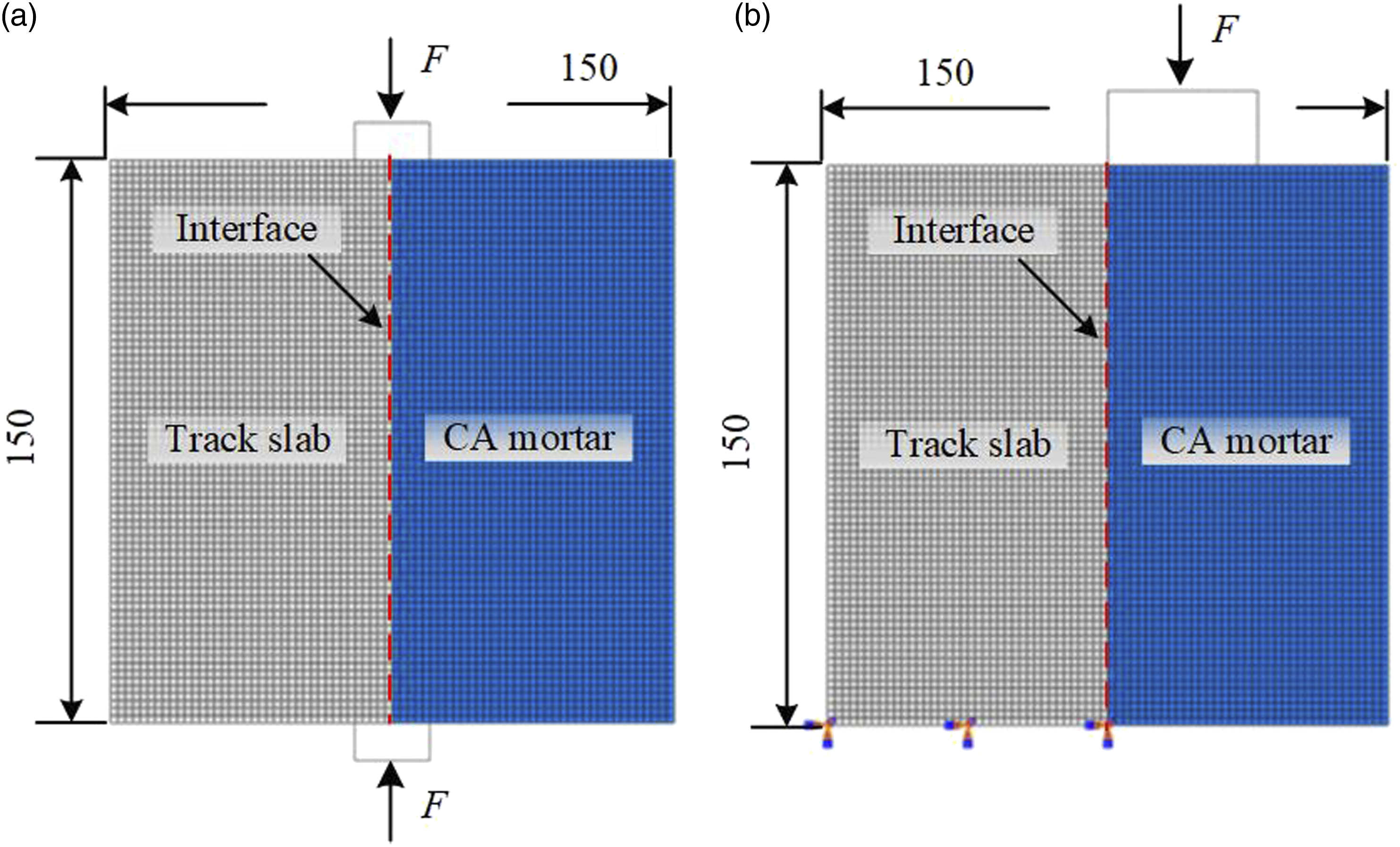
The comparison of finite element simulation results and experimental data is shown in Figure 5. It can be seen that the numerical simulation results agree well with the experimental data. Therefore, the bilinear CZM used in this study can well reflect the interface cracking behavior, which provides a basis for the damage analysis of the interface between track slab and CA mortar. Comparison of interfacial traction-separation relationships obtained from numerical simulation and experimental measurements: (a) Splitting, (b) Shear.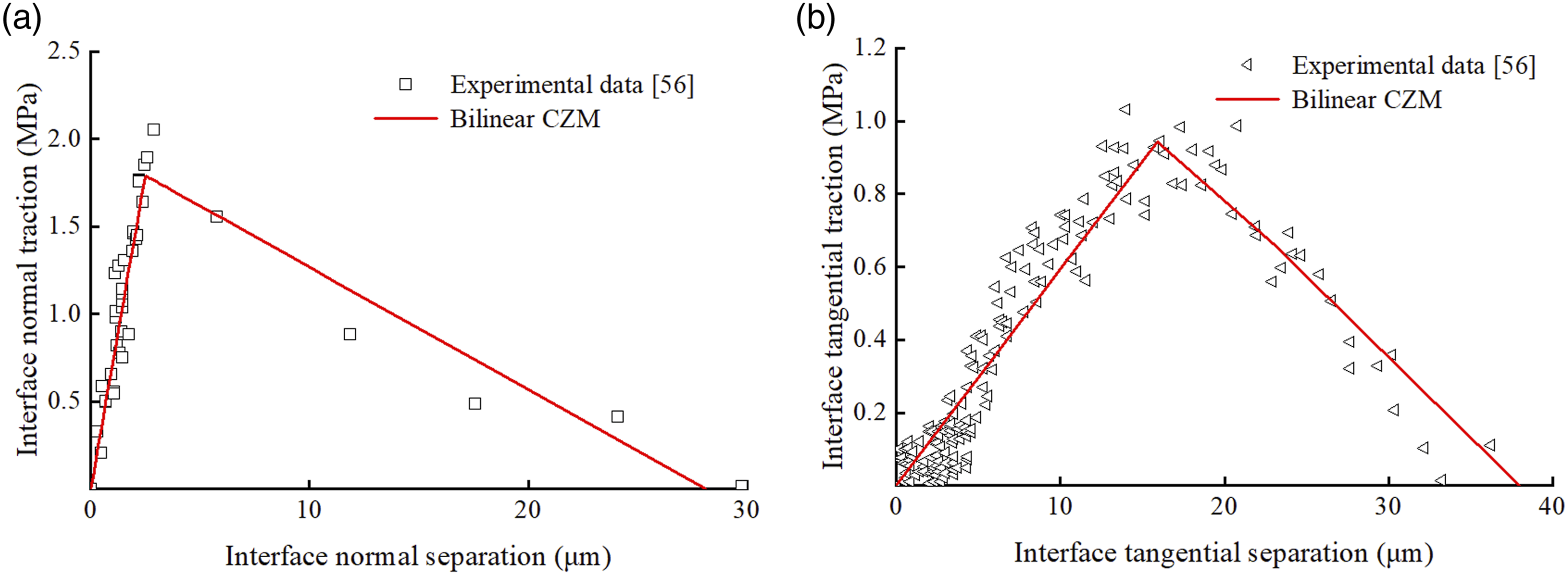
Verification of track structure deformation
To verify the accuracy of the FEM of CRTS II slab ballastless track, the simulation results are compared with the field experimental data. 57 To match the test conditions in the field experiment, the FEM does not consider the effect of longitudinally tensioned steel bars and the interaction between track slabs.
The deformation response of CRTS II slab ballastless track structural model is obtained under the same temperature gradient (denoted by T
g
) as that in the Ref. [57], i.e., 81.375°C/m and −40.600°C/m. The deformation of track slab is shown in Figure 6(a) and (b). The maximum upper arch displacement of track slab computed by the FEM is 0.492 mm and 0.391 mm for T
g
= 81.375°C/m and −40.600°C/m, respectively, which are close to the experimental results of 0.470 mm and 0.420 mm for T
g
= 81.375°C/m and −40.600°C/m, respectively.
57
This proves the accuracy of the FEM of CRTS II slab ballastless track. Model validation: (a) Under positive temperature gradient, (b) Under negative temperature gradient (unit: m).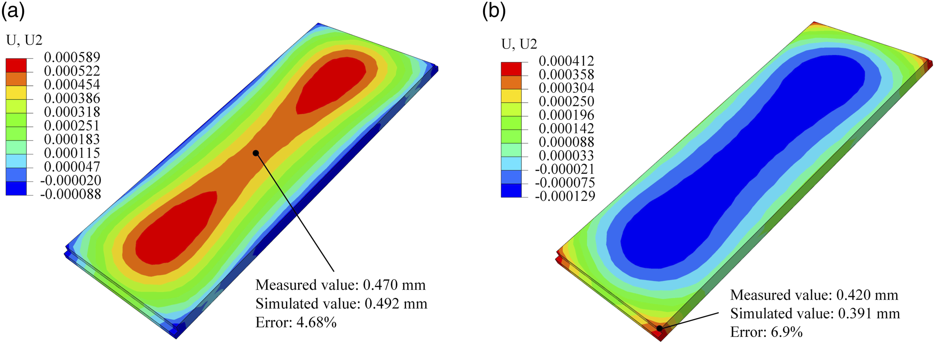
Analysis of interface damage mechanism
Selection of temperature value and location of initial gap damage
To reflect the practical condition, different combinations of overall temperature and temperature gradient are considered to investigate the interface damage mechanism. 10 values of overall temperature (denoted by ΔT) are considered, which changes from −50°C to 40°C with an interval of 10°C; five values of positive temperature gradient (denoted by
If the longitudinal edge sealing is not tight or the exhaust hole is set unreasonably during the construction process, it will be difficult to eliminate the bubbles in CA mortar, which will lead to the local initial gap damage between the track slab and CA mortar layer. According to the dense area of mortar bubbles, the local gap area mainly occurs in the slab end and slab edge. In the initial gap stage, the interface between the track slab and CA mortar is assumed to be completely damaged, while the interfaces are in contact with each other. Thus, in the FEM, the initial gap is modeled by making the bonding strength of cohesive element equal to zero, and the corresponding height is zero. Different transverse and longitudinal dimensions are set for the initial gaps, details will be discussed in the section “The influence of initial gap damage on the track structure”. Under the temperature action, the interfaces at the midpoint of the slab end (point A) and slab corner (point B) are prone to damage, as shown in Figure 7. Points selected for interface damage analysis.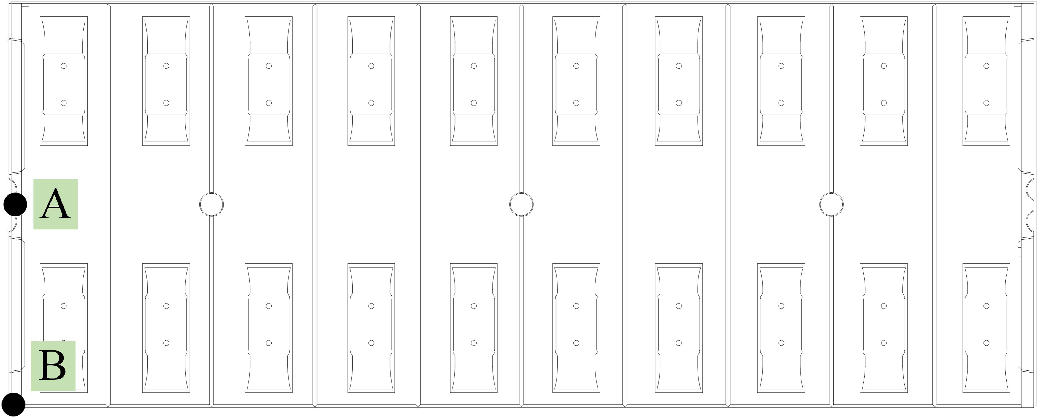
Analysis of interface damage evolution under temperature action
The interface damage state under temperature action is characterized by indicators including the damage initiation index (denoted by D ini ) and the damage factor (denoted by D), 58 which can be calculated by the FEM of CRTS II slab ballastless track. D ini and D are dimensionless variables with the range of [0, 1]. When D ini = 0, the interlayer bonding is intact and there is no damage at the interface; When D ini = 1, the interface begins to produce damage, but D is 0 in this process. With the development of interface damage, D increases gradually. When D reaches 1, the interface stiffness degrades and the interlayer is separated from joints. In summer, the overall temperature of the track structure is positive (denoted by ΔT + ), whereas the overall temperature is negative (denoted by ΔT − ) in winter. In the daytime, the surface temperature of the track slab is higher than that of the bottom, and corresponding temperature gradient is positive. On the contrary, the temperature gradient is negative at night. Therefore, at different time, the track is subjected to different combinations of overall temperature and temperature gradient, and it is necessary to analyze the impacts of all different cases on the interface damage.
Combination of overall temperature rise and positive temperature gradient
Under different values of ΔT
+
and Interface damage under overall temperature rise and temperature gradient: (a) Damage initiation index of point A under positive temperature gradient, (b) Damage initiation index of point B under positive temperature gradient, (c) Damage factor of point B under positive temperature gradient, (d) Damage initiation index of point A under negative temperature gradient, (e) Damage initiation index of point B under negative temperature gradient, and (f) Damage factor of point B under negative temperature gradient.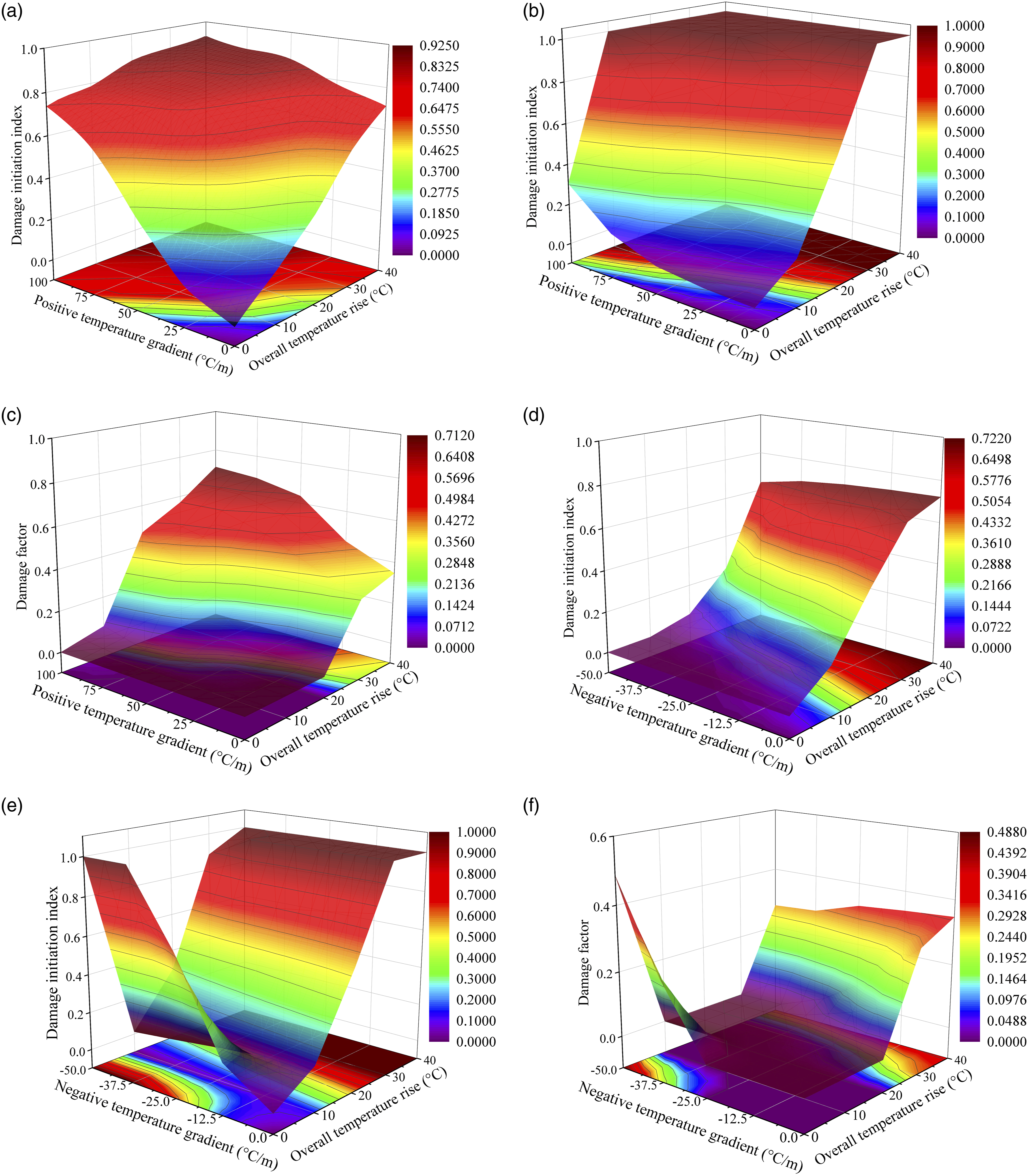
The maximum D at point B is 0.7106 (as shown in Figure 8(c)). As shown in Figure 8(c), when ΔT+≥30°C, the interface will be damaged even without positive temperature gradient. This shows that the positive overall temperature has an obvious effect on interface damage of point B, and the slab corner (point B) is damaged firstly under the action of positive temperature.
Combination of overall temperature rise and negative temperature gradient
Under different values of ΔT
+
and
When ΔT
+
is relatively large (larger than 25°C), the interface damage of points A and B will develop with the decrease of
Combination of overall temperature drop and negative temperature gradient
Under different values of ΔT
−
and Interface damage under overall temperature drop and temperature gradient: (a) Damage initiation index of point A under negative temperature gradient, (b) Damage initiation index of point B under negative temperature gradient, (c) Damage factor of point B under negative temperature gradient, (d) Damage initiation index of point A under positive temperature gradient, (e) Damage initiation index of point B under positive temperature gradient, and (f) Damage factor of point B under positive temperature gradient.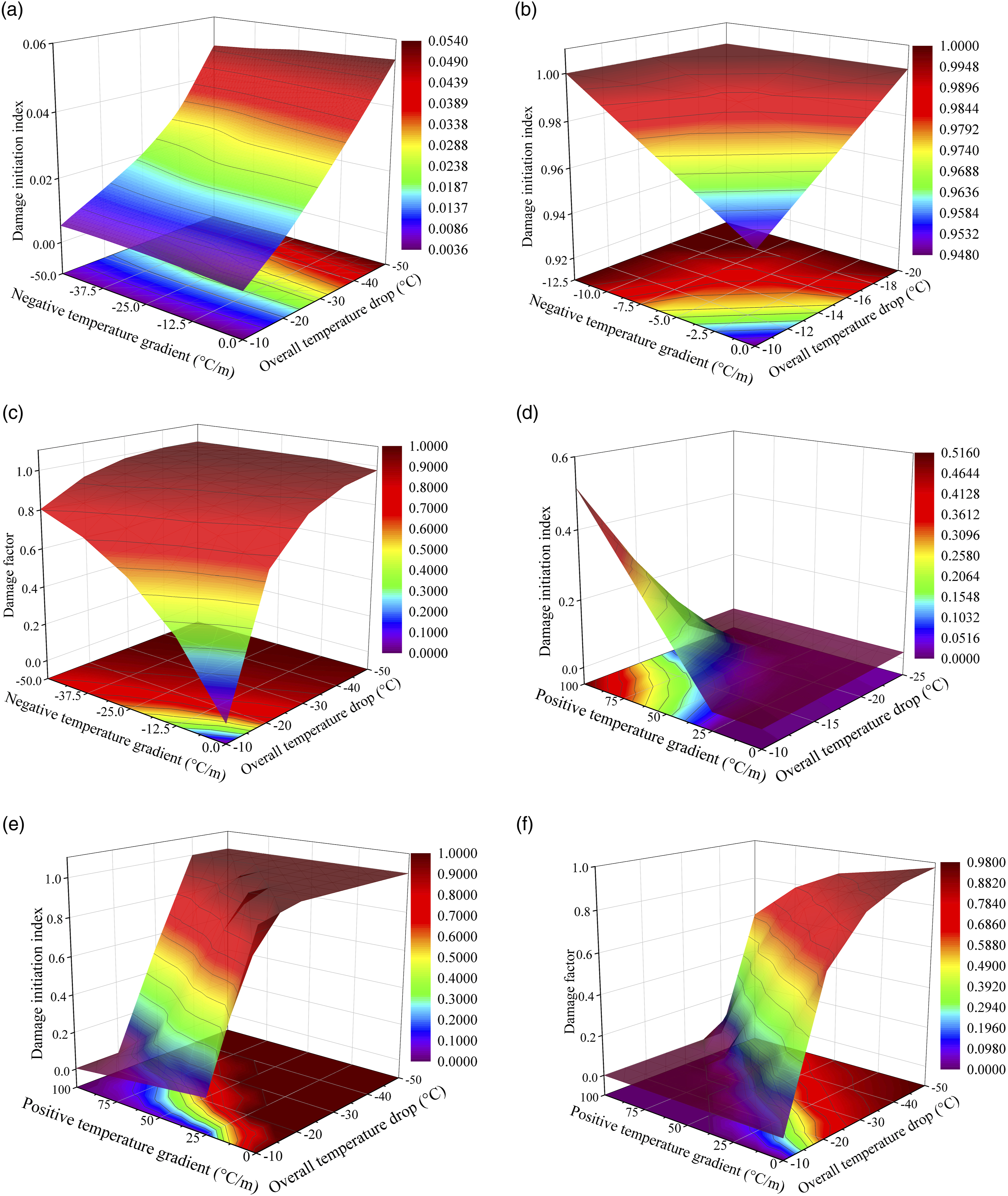
The damage at points A and B develops with the increase of ΔT
−
. When ΔT
−
= −50°C and
D at point B increases with the increase in ΔT
−
and
Combination of overall temperature drop and positive temperature gradient
Under different combinations of ΔT
−
and
When ΔT
−
< −10°C, the interface damage of point A and B develops with the increase of overall temperature drop. The overall temperature has a greater impact on the damage of point B than that of point A. This is caused by the lateral shrinkage deformation of track slab under the action of negative overall temperature. As shown in Figure 9(d), it can be seen that the D
ini
of point A is always less than 1, indicating that there will be no damage at the interface. When the overall temperature drop is small, the D
ini
of point A increases with the increase of positive temperature gradient. When ΔT
−
= −10°C and
Interface damage under temperature combination
Under different values of overall temperature, the change law of D at point B with T
g
is shown in Figure 10. When ΔT = 0°C or T
g
= 0°C/m, only the effect of temperature gradient or overall temperature is considered; When ΔT ≠ 0°C and T
g
≠ 0°C/m, the overall temperature and temperature gradient are considered simultaneously. It can be observed from Figure 10 that D under combined action of overall temperature and temperature gradient is not a simple superposition of those considering these two actions separately. For example, under the action of only ΔT
+
= 40°C or Damage analysis of the interface under temperature gradients: (a) Overall temperature rise, (b) Overall temperature drop.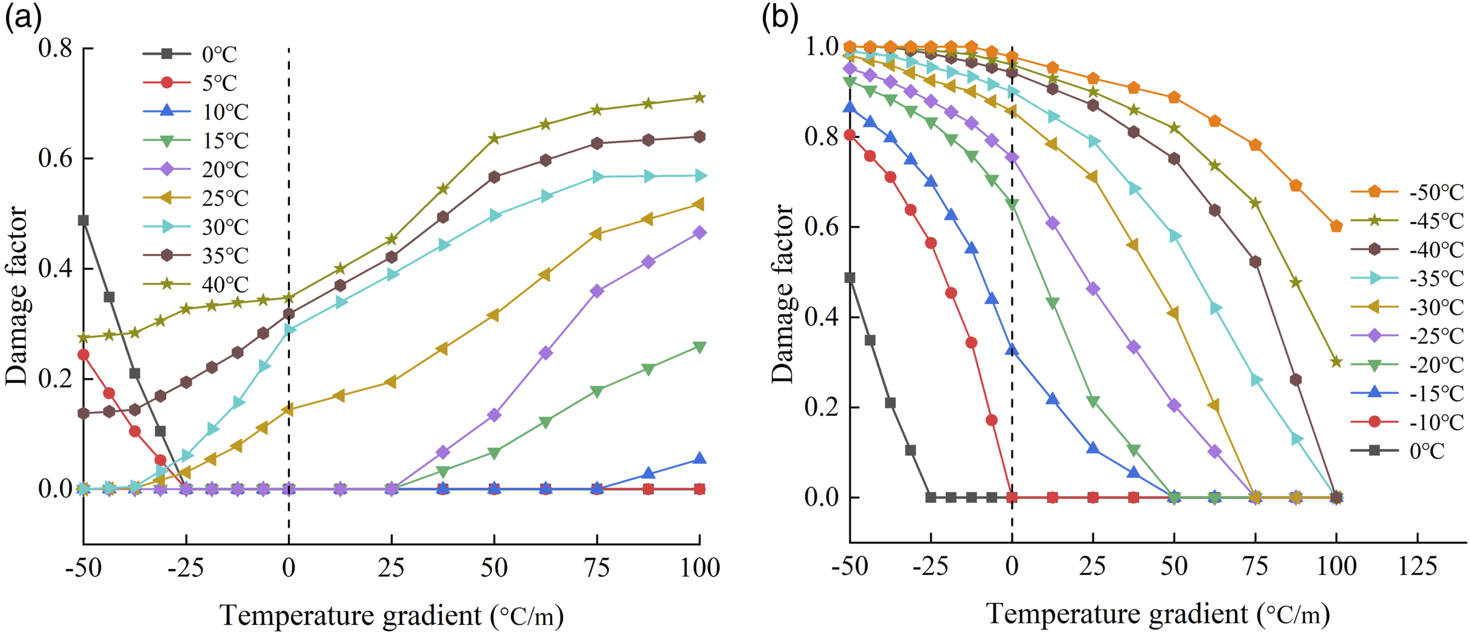
The interface damage law is also different under different combinations of overall temperature and temperature gradient. It can be seen from Figure 10(a) that, when 0°C ≤ ΔT ≤ 5°C, D first decreases and then remains unchanged. For example, when
It can also be observed from Figure 10(b) that, when ΔT < 0 and T g ∈[−50°C/m, 100°C/m], D gradually decreases with ΔT increases. However, with the increase in ΔT, the decrease rate of D will slow down. For example, when T g increases from −50°C/m to 100°C/m, D decreases by 0.8043 and 0.3984 with ΔT − = −10°C and ΔT − = −50°C, respectively.
Therefore, under the combined action of overall temperature drop and negative temperature gradient, the interface damage factor of the slab corner is greater than 0.8, and the possibility of producing gap damage is greater. At this time, maintenance action should be performed, such as the measure of post-installed rebar for preventing camber of the slab or the buckle limit device installed on the slab corner.23,59
The influence of initial gap damage on the track structure
In this section, the influence of initial gap damage on the interface damage mechanism of CRTS II slab ballastless is investigated. The initial gap damage is assumed to occur at the end or edge of track slab with different dimensions. The most adverse temperature action conditions are considered: ΔT
+
= 40°C and T
g
= 0°C/m, ΔT
−
= −50°C and T
g
= 0°C, ΔT = 0°C and
According to TG/GW 115-2012 “Maintenance Rules for Ballastless Track of High-Speed Railway”, 60 the damage level of gap is divided into levels I, Ⅱ and III, and the corresponding heights of gap are 0.5 mm, 1.0 mm and 1.5 mm, respectively. Level I damage shall be marked for further observation, level II damage shall be listed in the maintenance plan and repaired timely, and level III damage shall be repaired in time.
Gap damage in slab end
In the case of slab end gap, transverse through initial gap damage is considered, i.e., the transverse dimension is the width of the track slab, with the longitudinal length set to be 1–4 fastener spacings (FSs) as shown in Figure 11(a). The local gap range: (a) Transverse through gap in the slab end, (b) Longitudinal through gap in the slab edge, and (c) Longitudinal non-through gap in the slab edge.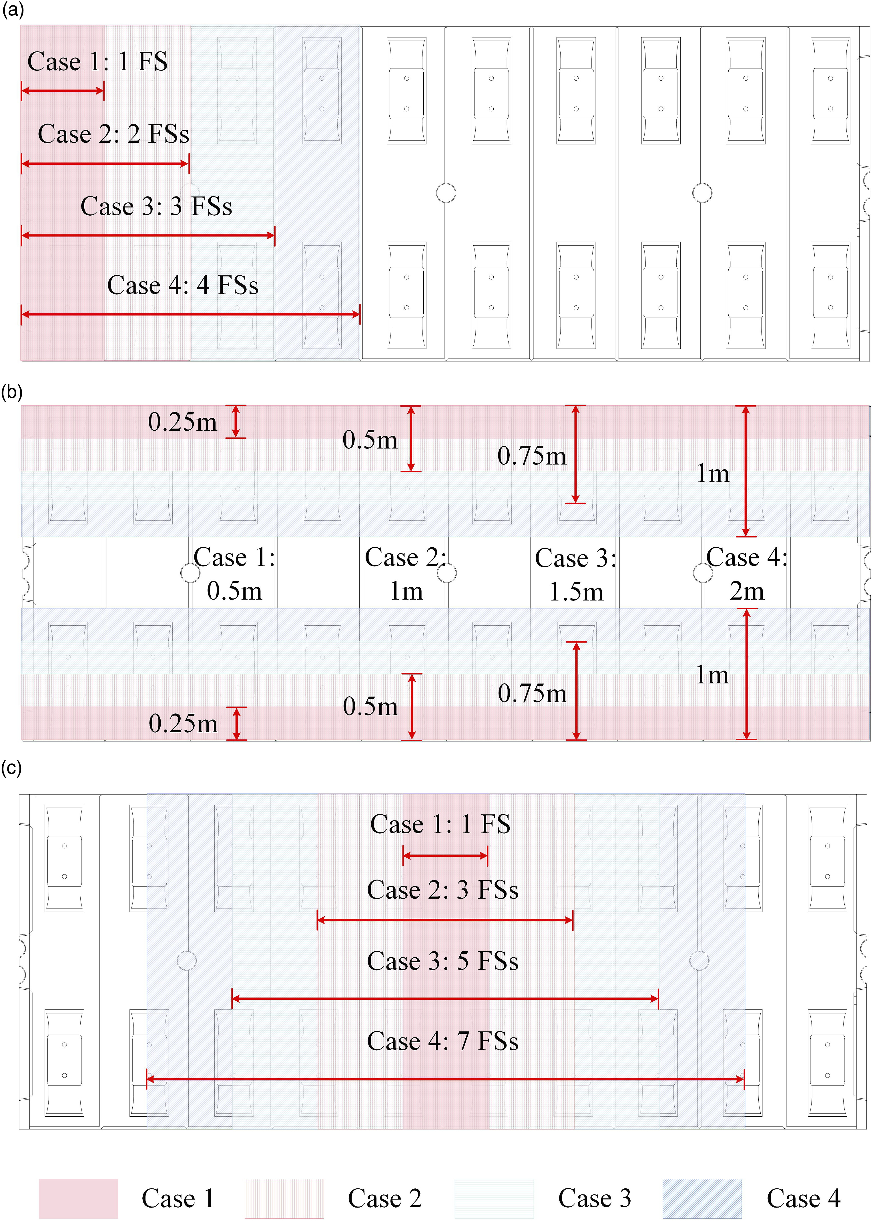
The variation law of the maximum vertical displacement of track slab and interface gap height with the gap length of slab end is shown in Figure 12(a) and (b), respectively. It can be found that: (1) The maximum vertical displacement and interface gap height under combined temperature actions are greater than those under single temperature action. With the increase of slab end gap length, the maximum vertical displacement of track slab and interface gap height gradually increases. The growth rate of maximum vertical displacement of track slab and interface gap height under positive temperature action combinations is greater than that under negative temperature action combinations. (2) It can be seen from Figure 12(a) that, for ΔT
+
= 40°C and (3) According to Figure 12(b), for ΔT
+
= 40°C and The influence of slab end gap length on the maximum vertical displacement, interface gap height and interface damage under different temperature combinations: (a) Maximum vertical displacement of track slab, (b) Interface gap height, (c) Displacement contour of the track slab under 40°C and 100°C/m when the slab end is separated from 4 FSs (unit: m), and (d) Interface damage.
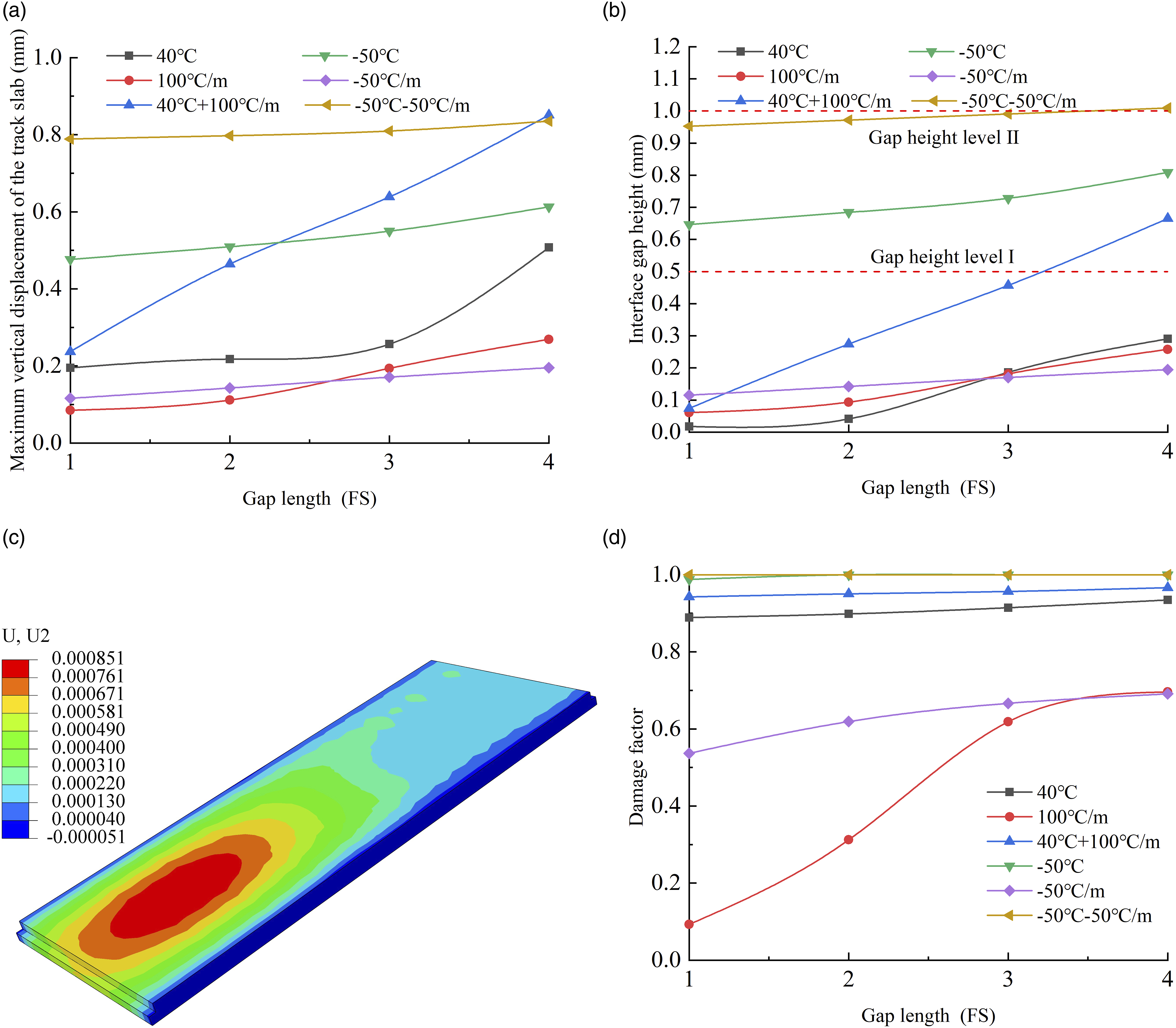
Under different temperature actions, the change law of interface damage between track slab and CA mortar layer with the gap length of slab end is shown in Figure 12(d). The interface damage under combined temperature actions is greater than that under single temperature action. With the increase of gap length, the growth rate of interface damage under temperature gradient is greater than that under overall temperature. It shows that under the temperature gradient, the gap length has an obvious effect on the interface damage. When ΔT − = −50°C and gap length is greater than 1FS, the interface damage factor reaches one and the interface begins to delaminate.
Gap damage in slab edge
In this section, longitudinal through and non-through initial gaps are considered with different transverse dimensions: (1) When the longitudinal initial gap is through, four cases are considered with the width from the edge set to be 0.5 m, 1 m, 1.5 m, and 2 m, respectively. (2) When longitudinal initial gap is non-through, four cases are also investigated, where the lateral gap width is 2 m and the longitudinal gap length is 1 FS, 3 FSs, 5 FSs, and 7 FSs, respectively. The local gap range of slab edge is shown in Figure 11(b) and (c).
Longitudinal through gap in the slab edge
The variation law of the maximum vertical displacement of track slab and interface gap height is shown in Figure 13(a) and (b), respectively. It can be found that: (1) With the increase of the gap width of slab edge, the maximum vertical displacement of track slab and interface gap height increase gradually. (2) When ΔT
−
= −50°C and The influence of slab edge gap width on the maximum vertical displacement, interface gap height and interface damage under different temperature combinations: (a) Maximum vertical displacement of track slab, (b) Interface gap height, (c) Displacement contour of the track slab under −50°C and −50°C/m when the gap width reaches 2 m (unit: m), and (d) Interface damage.
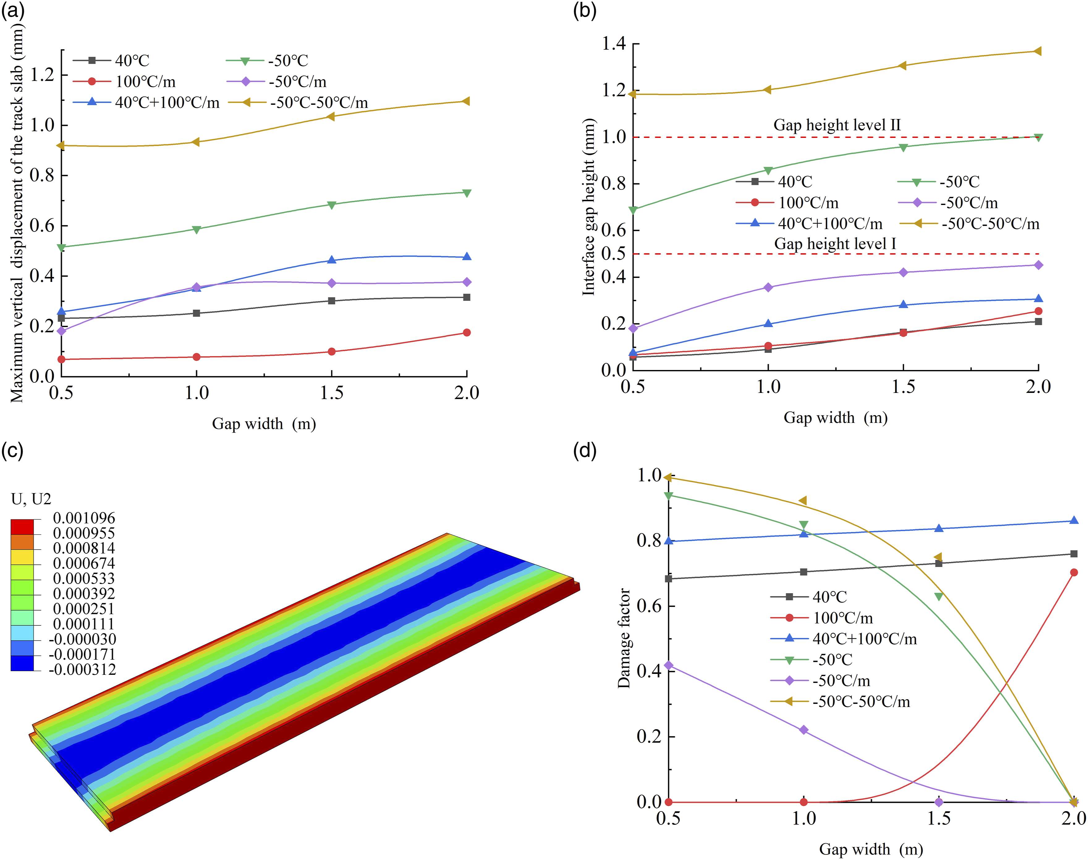
From Figure 13(b), it can be seen that when ΔT
+
= 40°C and
Under different temperature actions, the change law of interface damage between track slab and CA mortar layer with the gap width of slab edge is shown in Figure 13(d). When temperature gradient and overall temperature are positive, the interface damage increases with the increase of the slab edge gap width. When ΔT
+
= 40°C and
Longitudinal non-through gap in the slab edge
The variation law of the maximum vertical displacement of track slab and interface gap height with the gap length of slab edge is shown in Figure 14(a)–(b), respectively. It can be found that: (1) With the increase of slab edge gap length, the maximum vertical displacement of track slab and interface gap height increase gradually. When ΔT
−
=−50°C and (2) When ΔT
+
= 40°C and The influence of slab edge gap length on the maximum vertical displacement, interface gap height and interface damage under different temperature combinations: (a) Maximum vertical displacement of track slab, (b) Interface gap height, (c) Displacement contour of the track slab under −50°C and −50°C/m when the gap length is 7 FSs (unit: m), and (d) Interface damage.
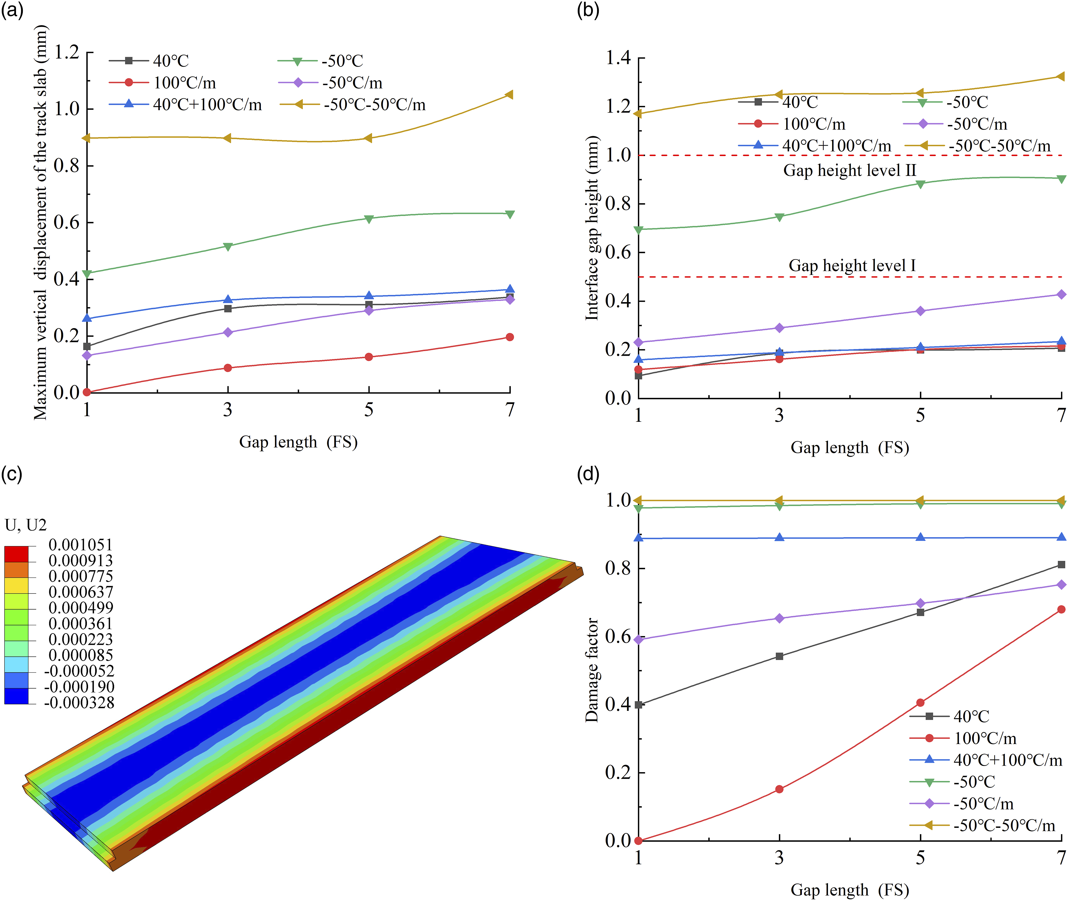
Under different temperature actions, the change law of interface damage between track slab and CA mortar layer with the gap length of slab edge is shown in Figure 14(d). The interface damage increases with the increase of slab edge gap length. Under the action of single positive temperature actions, the growth rate of interface damage increases with the increase of slab edge gap length. When ΔT
+
= 40°C and
Conclusions
In this study, a three-dimensional FEM of CRTS Ⅱ slab ballastless track is established, based on which the mechanism of interface gap damage was analyzed under different combinations of overall temperature, temperature gradient, and initial interface local gap. The following main findings can be drawn: 1. The overall temperature has a more obvious effect on interface damage than temperature gradient. When the overall temperature is greater than 30°C, the interface at the slab corner will be damaged even without temperature gradient. 2. Under negative overall temperature, the interface damage at the slab corner will become more severe with the increase of temperature gradient. In contrast, under positive overall temperature, the level of interface damage gradually decreases with the increase of temperature gradient. 3. For the slab end gap, the interface gap damage reaches level II (according to TG/GW 115-2012) when the gap length reaches 4 FSs under the combined action of negative temperatures. However, the maximum vertical displacement growth rate of track slab under positive temperature combinations is greater than that under negative temperature combinations. The growth rate of interface damage under temperature gradient is greater than that under overall temperature. When the overall temperature drop is −50°C and gap length is greater than 1FS, the interface damage factor reaches one and the interface begins to delaminate. 4. For the slab edge gap, the interface gap damage reaches level II (according to TG/GW 115-2012) when overall temperature drop and temperature gradient reach −50°C and −50°C/m, respectively. The interface damage increases with the increase of the slab edge gap length, while the slab center interface is unlikely to be damaged with the increase of the gap width of slab edge under negative temperature. 5. The law of interface damage is more complex under the combined action of overall temperature, temperature gradient and initial gap damage than that under these actions separately. Simultaneously, the existence of initial gap damage will accelerate the development of interface damage. It is more unfavorable to the service safety of the track structure.
It should be noted that only the effect of short-term temperature actions is considered for the investigation of interface damage development between track slab and CA mortar layer in this study. Since temperature action always exist in the service life of the structure, the effect of long-term temperature actions (i.e., fatigue cracking of the interface) should be considered for the long-term service reliability of track structure and safety operation of high-speed trains.61,62 Further study on this issue is necessary and will be conducted in future.
Footnotes
Declaration of conflicting interests
The author(s) declared no potential conflicts of interest with respect to the research, authorship, and/or publication of this article.
Funding
The author(s) disclosed receipt of the following financial support for the research, authorship, and/or publication of this article: The study was partially supported by the National Natural Science Foundation of China (Grant No: 51820105014, 52108104, 52278135, U19342171), the Higher Education Discipline Innovation Project (Grant No. D21001), Science and Technology Research and Development Program Project of China Railway Group Limited (2020-Special-02). The supports are gratefully acknowledged.