
Abstract
Owing to the blunt car body and high design speed of express freight trains, the running safety is significantly affected by crosswinds when the train runs over a bridge; moreover, severe accidents, such as derailment or overturning may occur. Therefore, adequate measures should be adopted to avoid the occurrence of such accidents. In this study, a finite element model of the train, ballastless track, and parameterized 5-span simply supported girder bridge along with modal superposition method are adopted to establish the train-track-bridge coupling dynamic system. Numerical simulation of stochastic wind speed, wind tunnel tests, and computational fluid dynamics (CFD) simulation of vehicle-bridge scale model were conducted to calculate the wind load acting on the train and bridge. The dynamic responses of the bridge and train were evaluated to present the diagrams of wind and train speed limits for safe operation. The results indicated that the running safety of the vehicle declined with the wind and train speeds, and the wheel unloading rate was the most sensitive to wind speed. For safe operation, the train speed must be restricted if the mean wind speed is greater than 22.7 m/s, and an extreme scenario of derailment may occur for a mean wind speed of 34.0 m/s. In addition, the wind speed limit should be appropriately adjusted and improved according to the pier height of the bridge and terrain category. This research provides a theoretical basis and data support for the assessment of safety of express freight trains in actual operation.
Keywords
Introduction
With the rapid development of e-commerce and railway freight logistics, research on express freight trains has accelerated with an aim to improve freight capacity and meet the demand for efficient transportation. Express freight trains have heavy load and higher design speed compared with traditional freight trains; therefore, when they run over a bridge, the coupled vibration of the vehicle-bridge system is aggravated, which not only affects the serviceability of the bridge structure but also influences the running safety of the train. In addition, as a typical natural phenomenon, a strong crosswind may further intensify the structural vibration of bridges, worsen the running safety, and even cause extreme scenarios of derailment and overturning. This problem is particularly evident when the train runs over bridges situated in mountainous or urban areas owing to the complex terrain and long wind periods. Hence, it is important to analyse the influence on train behaviour and propose measures and suggestions to ensure safe operation.
Several studies regarding running safety of trains in crosswind have been published in recent years and reasonable suggestions for safe operation have been proposed.1–7 Montenegro et al.1–5 investigated the influence of different factors related to the train-track-bridge structure coupling system on the running safety and stability of the train against crosswind such as the train type, track condition and the bridge behaviours, and defined the limit values of the train and wind speeds based on various running safety criteria allowances. Wang et al. 6 propose a methodology for analysing the global reliability of running safety of the train traversing a bridge under crosswind using the probability density evolution method combined with the extreme value principle. He et al. 7 established a coupled vibration analysis model of a high-speed train and bridge under the influence of non-stationary winds based on the pseudo-excitation method and concluded that the coupled vibration responses are larger than those under the influence of stationary winds; however, the effects of non-stationary winds on the bridge responses are relatively more sensitive compared to those of the train.
To evaluate the dynamic responses of a train running in crosswind, it is important to investigate the aerodynamic characteristics and calculate the wind load of the vehicle. Current research works evaluate the aerodynamic parameters of trains and bridges mainly through wind tunnel tests or CFD simulations.8–10 Since CFD simulation is susceptible to calculation factors, such as meshing and solution methods, wind tunnel tests are conducted for the purpose of comparison. Yao et al. 8 investigated the aerodynamic characteristics associated with a train and bridge in crosswind through CFD simulation, and they developed a fitting formula for a variety of yaw angles to predict the wind load acting on the vehicle. Bocciolone et al. 9 investigated the aerodynamic characteristics of an ETR-480 train on a bridge using wind tunnel tests. It was found that the aerodynamic behaviours of the leading and second vehicles were considerably different, and the wind angle of attack had a significant influence on the aerodynamic coefficients of the leading vehicle. However, owing to the blunt car body, large sidewall area, and high mass centre of the box wagon, express freight vehicles are more susceptible to crosswind loads. To evaluate the influence of aerodynamic characteristics on the train running safety and define the criteria allowances, the aerodynamic parameters cannot be obtained from the experience datum of a similar type of vehicle simplistically or by considering the leading vehicle as the riskiest vehicle to assess the running safety of the train. Kikuchi and Suzuki 10 conducted wind tunnel tests and analyse the effect of aerodynamic coefficients on the critical wind speed based on a static overturning evaluating model; however, only the leading vehicle were put for the object and the dynamic responses of the bridge were not taken into consideration. Practically, unlike high-speed train, many wind-induced accidents in freight trains are caused by the derailment or overturning of trailers rather than the leading traction locomotive.11,12 In December 1986, when a freight train passed through the Shanyin Bridge at a speed of 55 km/h, all the vehicles from the second trailer to the last fell off the bridge under the influence of crosswind load. 11 In China, more than 30 operational accidents induced by crosswinds have occurred in the line from Lanzhou to Xinjiang since 1966, and the derailed and overturned vehicles were generally box wagons. 12 Therefore, it is vital to investigate the aerodynamic behaviours of trailers to assess the running safety of express freight trains.
In China, prestressed concrete bridges account for more than 90% of the total mileage of medium and high-speed railway bridge lines among which simply supported girder bridges are the most widely used owing to their simple structure and convenient erection. The structural form of a girder bridge is related to various factors, such as the line environment and train operation safety. Bridges with short spans and pier heights are often erected in urban areas and towns; however, large spans and pier heights are mostly found in mountainous areas due to the complex terrain. 13 Because the short span is close to the vehicle length, resonance between the vehicle and bridge may occur in certain speed ranges. In addition, bridges with large pier heights have worse structural stability under the action of crosswinds compared to short-pier bridge.14–16 Olmos and Astiz14,15 conducted research on the lateral responses of a bridge and train when high-speed trains travelled over long viaducts with high piers, and the results showed that the deck lateral relative displacement inside a span exceeded the criteria of bridge standards, which can be solved by increasing the pier stiffness. Moreover, when encountering a strong crosswind, trains normally decrease the speed or even stop according to the specified wind speed limit in actual operation. 17 Because the limit is a generic value and does not distinguish bridges of different forms, certain bridge environments may still be prone to potential risks. Hence, assessing the running safety of trains in accordance with bridges with different structural parameters is of practical significance.
In this study, a dynamic model of wind-train-track-bridge coupling system is established to assess the running safety of the express freight train when it runs over a bridge in crosswind. Wind tunnel tests and CFD simulations of the vehicle-bridge scale model are conducted to analyse the aerodynamic characteristics of express freight vehicles on the bridge. Parameterized 5-span simply supported girder bridges with spans of 24, 32, and 40 m and pier heights ranging from 10 to 50 m are adopted to evaluate the dynamic responses when the train crosses the bridges with different structural parameters, and the diagrams of wind and train speed limits for safe operation are presented. Besides, the relationship between wind speed limit and pier height in different terrain categories is analysed.
Dynamic model of express freight train-track-bridge coupling system
A detailed dynamic model of the train-track-bridge coupling system was established in real operating environment as shown in Figure 1(a). The express freight train, track, and simply supported girder bridge are considered as three subsystems and wind loads are the external excitations loaded on the vehicle and bridge subsystems. Dynamic model of express freight train-track-bridge coupling system (a) Express freight train-track-bridge coupling system (b) Finite element model (FEM) of vehicle (c) FEM of 5 span simply supported girder bridge (d) Cross-section of main beam (e) Sample of vertical irregularity (f) Wheel-rail contact geometry.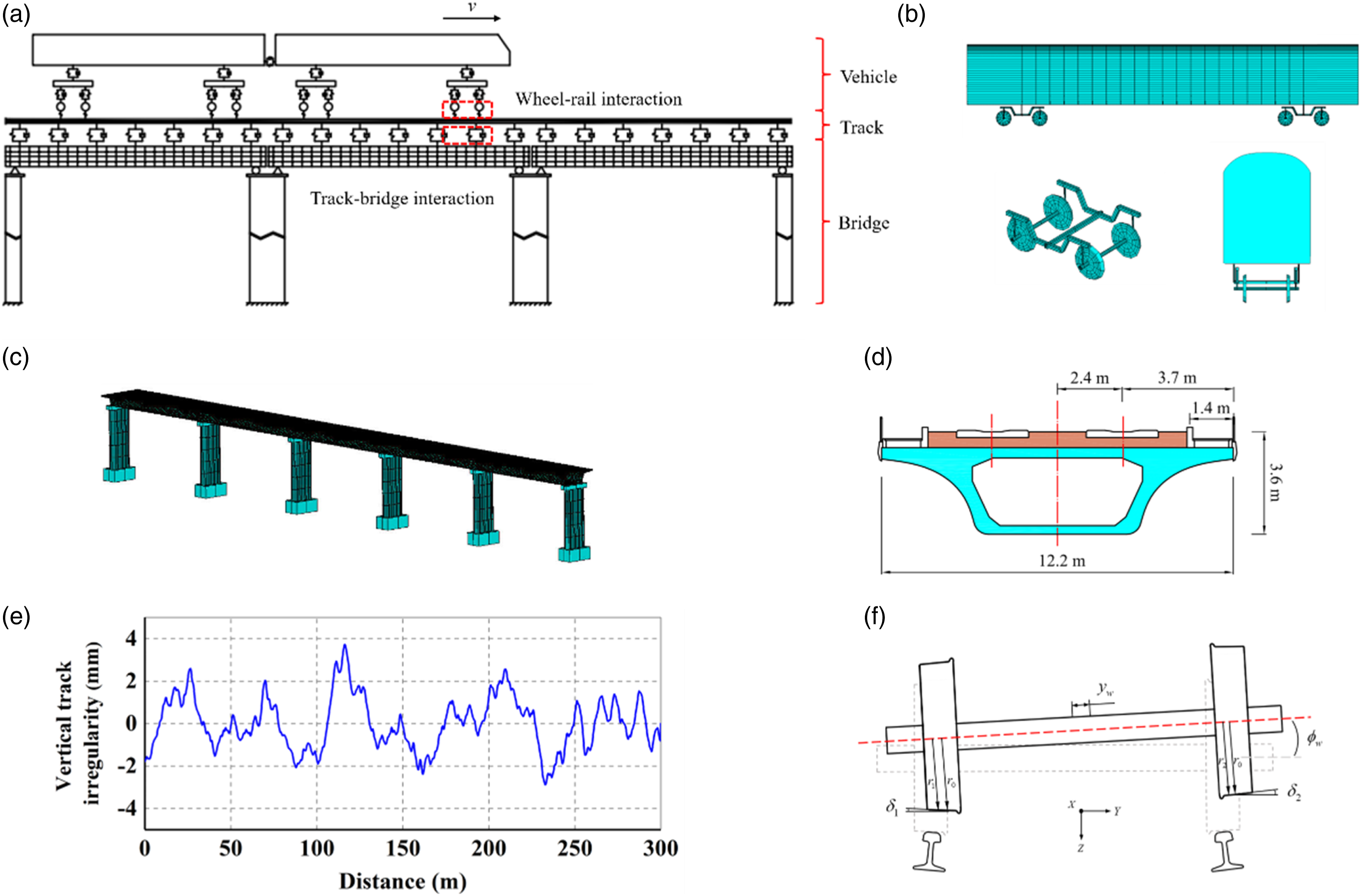
Dynamic model of express freight train
Express freight trains adopt the formation of 1M + 20T in the actual operation. The leading vehicle is the traction locomotive and trailers are box wagons. In this study, the vehicle is modelled as a FEM using ANSYS. 18 Each vehicle consists of a car body, two bogies, and four wheelsets (Figure 1(b)). A total of 35 degrees of freedom (DOF) are considered for one vehicle. In this study, each part of the vehicle was considered as a rigid body by assigning a large elastic modulus to the elements, and modal superposition method was adopted to establish the dynamic equation of the train subsystem by extracting the vibration modes of the corresponding DOFs. In addition, the stiffness and damping of the primary and secondary suspension systems of the vehicle are modelled as linear spring-viscous damping.
Dynamic model of track and bridge
As shown in Figure 1(c), FEMs of double-block ballastless track and 5-span simply supported girder bridge are established as the bridge subsystem using ANSYS. The cross-section of the main beam is shown in Figure 1(d). In the modelling, the rails, main beams, and piers are implemented by the beam element BEAM188 with real sections as designed, and the coupling DOFs are adopted to simulate the hinged support. In addition, a parametric bridge model is applied to investigate the distinction of dynamic responses when the train passes through the bridge with different spans and pier heights. The US Level 6 track irregularity spectrum 19 with a wavelength ranging from 1 to 100 m including vertical, lateral, roll, and gauge irregularities is applied. A sample of the vertical irregularities is shown in Figure 1(e).
Wheel-rail dynamic interaction
The wheel-rail dynamic interaction includes the wheel-rail contact geometry, wheel-rail normal forces, and wheel-rail creep forces, which are the conjunctions between the vehicle and track subsystems. In this study, the nonlinear wheel-rail spatially dynamic coupling model,20,21 which is also known as ‘jump model’, was adopted to analyse the contact geometry between the wheel and rail. It is assumed that the moving wheelset is not always in contact with the rail when travelling along the bridge as shown in Figure 1(f), which is capable of considering the situation of loss of wheel-rail contact under the effect of rail deformation and track irregularity. Taking the right wheel as an example, when the wheel is in contact with the rail, the position coordinate of the wheel-rail contact point can be expressed as
The wheelset of the express freight train adopts the LM wheel profile with a normal rolling circle radius of 0.4575 mm, matching R60 rail profile. The rail gauge and base slope are 1435 mm and 1:40, respectively. The description of wheel-rail contact geometry are as shown in Figure 2. Variation of (a) the radius of wheel rolling circle and (b) the wheel-rail contact angle with the lateral displacement of the wheelset (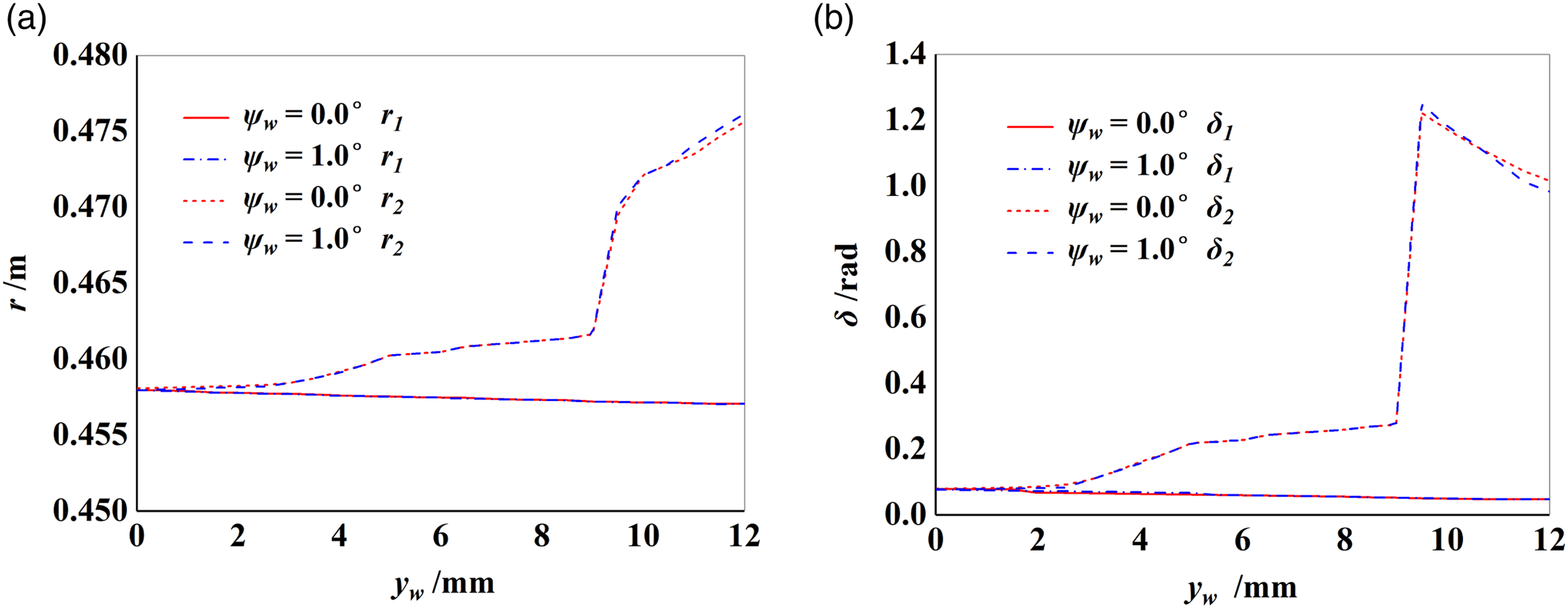
The wheel-rail normal forces are calculated based on the Hertz nonlinear contact theory 22 and the wheel-rail creep forces are calculated according to Kalker’s linear theory 23 and Shen-Hedrick-Elkins model. 24 When the instantaneous loss of contact occurs between one side of wheel and rail, the normal force and creep force reduce to 0.
Coupling model and numerical solution method
In the dynamic model of the vehicle-track-bridge coupling system based on the modal superposition method,
20
the equation of motion of the vehicle and bridge can be expressed as

where
Based on the train-track-bridge system dynamic equations given in equation (2), a separated iterative method and Newmark-β integral method were used in this study to calculate the dynamic responses of the system according to the process diagram in Figure 3. Procedure of numerical solution method.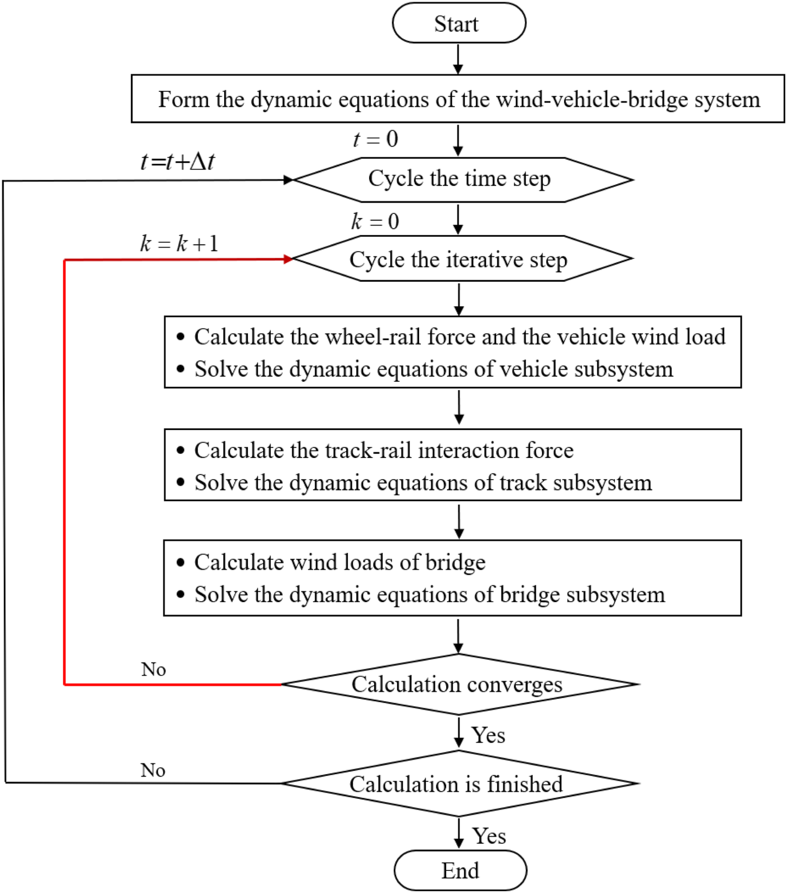
Method to calculate wind load on the vehicle and bridge
Numerical simulation of wind speed
According to the characteristics of atmospheric boundary layer (ABL) flow,
25
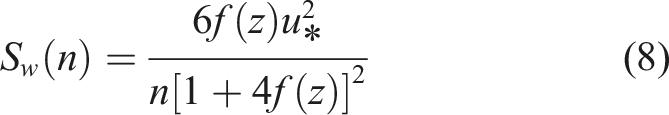
the natural unsteady wind speed can be expressed as

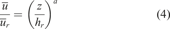
The fluctuating wind speed Diagram of the wind speed simulation and wind load (a) Wind speed and running speed of the vehicle (b) Wind speed simulation nodes of bridge and time history of crosswind speed at the position of mid-span of bridge (Pier height = 20 m) (c) Diagram of wind load.

According to the simulation method described in this section, the unsteady crosswind speed time history sample at the mid-span of the bridge is indicated by a thin blue line in Figure 4(b). If the fluctuation and stochasticity of wind speed are not considered, the mean wind speed is indicated by the dashed red line.
Wind load on the vehicle and bridge
The wind speed simulation and wind load acting on the vehicle and bridge subsystems in the crosswind are shown in Figure 4(a).

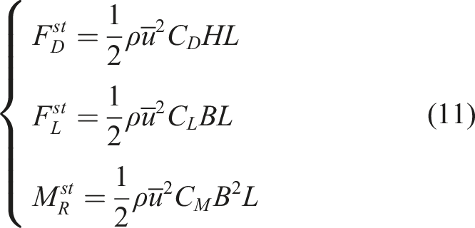
In a natural wind field, the wind load on the vehicle and bridge can be regarded as the sum of static wind load under the action of mean wind speed and buffeting wind load under the action of fluctuating wind speed. The static wind load of the vehicle or bridge segment can be described as
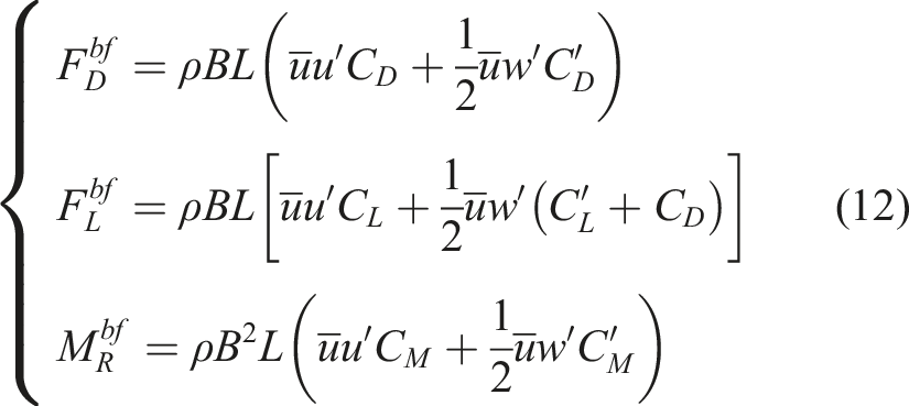
The buffeting wind load of the vehicle or bridge segment can be described as
Vehicles-bridge scale model wind tunnel test and CFD simulation
To investigate the aerodynamic characteristics and calculate the wind load on the vehicle, a scale model of an express freight vehicle and simply supported girder bridge wind tunnel test was conducted in the TJ-2 wind tunnel laboratory at Tongji University in China. The vehicle scale models include leading, middle, and tail vehicles, which are based on the express freight box wagon as shown in Figure 5(a). Two vehicle models for measuring the aerodynamic forces and pressure on the surface of the car body are placed behind the leading vehicle. In each test condition, the positions of the two models are exchanged to measure the aerodynamic forces and pressure of the vehicle at other positions. Owing to the size limitation of the wind tunnel, data of the leading vehicle were not measured. The aerodynamic characteristics were obtained from CFD simulation. Vehicles-bridge scale model wind tunnel test (a) Vehicles-bridge scale model wind tunnel test (b) Arrangement of force balance and pressure taps on the car body (mm) (c) Arrangement of vehicle and bridge models (d) Aerodynamic force coefficients of trailers.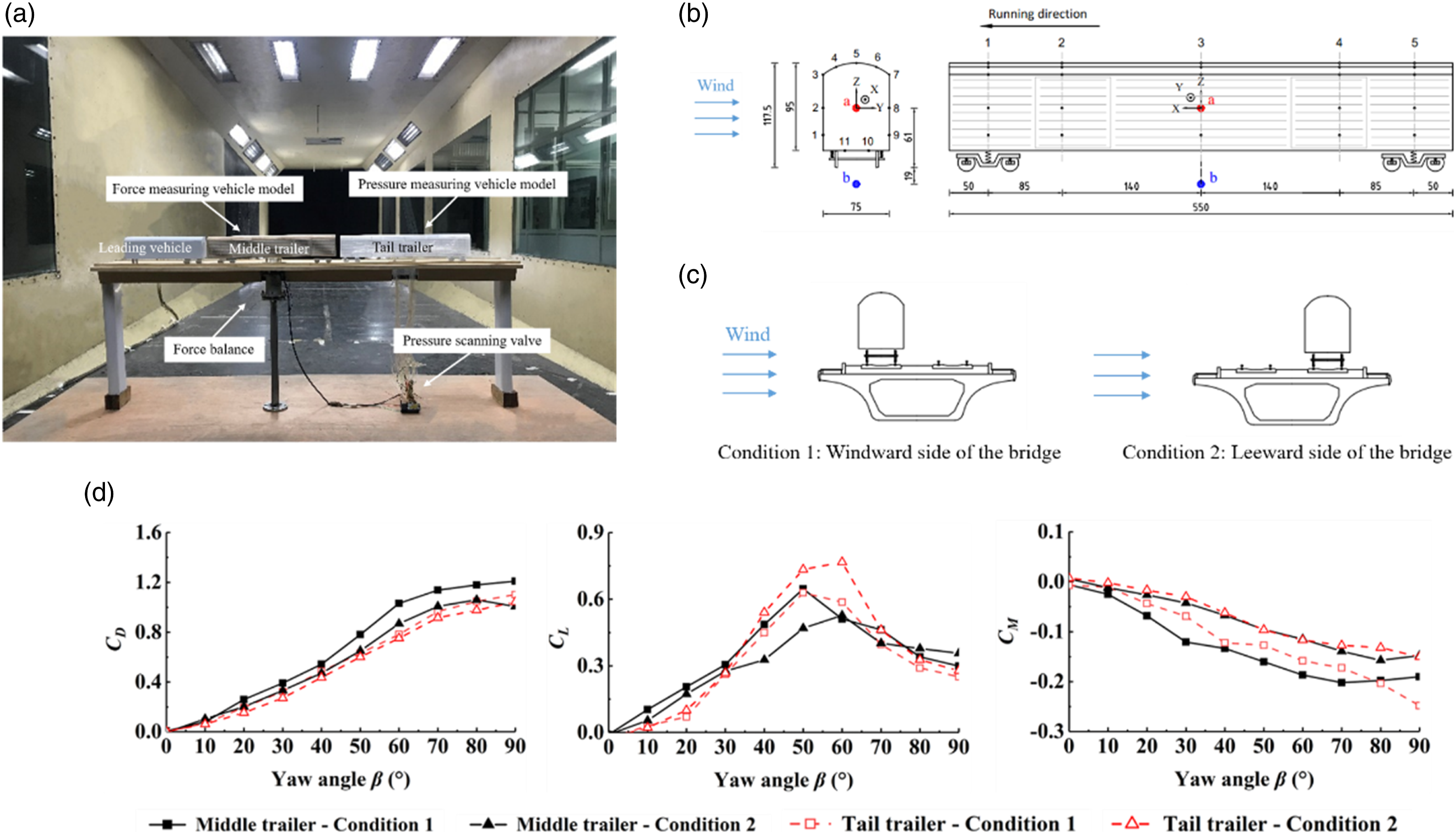
The aerodynamic forces of the car body are measured using a six-component force balance (ATI, USA 27 ), which is located at point b in Figure 5(b), and the aerodynamic forces are automatically converted to the centre equivalent of the car body (point a) during the test. The aerodynamic pressure on the surface of the car body is measured by an electronic pressure scanning valve (DSM3000 from Scanivalve, USA 28 ) in real time, and five sections of pressure taps are placed on the surface of the car body including the sidewall in the middle and above the bogie. The measurement points are evenly distributed on the roof, bottom, and sidewalls of the car body.
In the tests, the vehicle–bridge scale model rotated along with the turntable on the wind tunnel ground to change the angle relative to the airflow. The aerodynamic forces and pressure on the car body were measured at yaw angle in the range of −90° to 90° with an angle interval of 10°. In addition, two conditions (Figure 5(c)), namely the windward side (positive yaw angle, Condition 1) and leeward side (negative yaw angle, Condition 2) are considered to compare the aerodynamic characteristics of vehicles at different positions of the bridge.
From the measurement results shown in Figure 5(d), it can be seen that the absolute values of both the side force coefficient and rolling moment coefficient increase with an increment in yaw angle and the lift coefficient reaches the maximum value at a yaw angle
Owing to the limitations of the wind tunnel tests, the aerodynamic characteristics of the leading traction locomotive and bridge were obtained using CFD simulation through Fluent, which is one of many toolboxes within the ANSYS Workbench
18
suite of software applications. Figure 6(a) shows the calculation domain and boundary conditions where the domain size is defined as a function of the height of the car body. The wind speed at the velocity inlet is 20 m/s and reference pressure at the pressure outlet is 0 Pa. The bottom of the domain and bridge surface are set to no-slip conditions. Since the primary focus is on the time-domain average values, the Reynolds Average Navier-Stokes (RANs) simulation method and shear-stress transport (SST) k-ω model are adopted in this study. Vehicles-bridge scale model CFD simulation (a) CFD numerical simulation calculation domain (b) Calculation conditions (c) Flow field around the locomotive (d) Aerodynamic force coefficients of locomotive (e) Aerodynamic force coefficients of bridge and pier (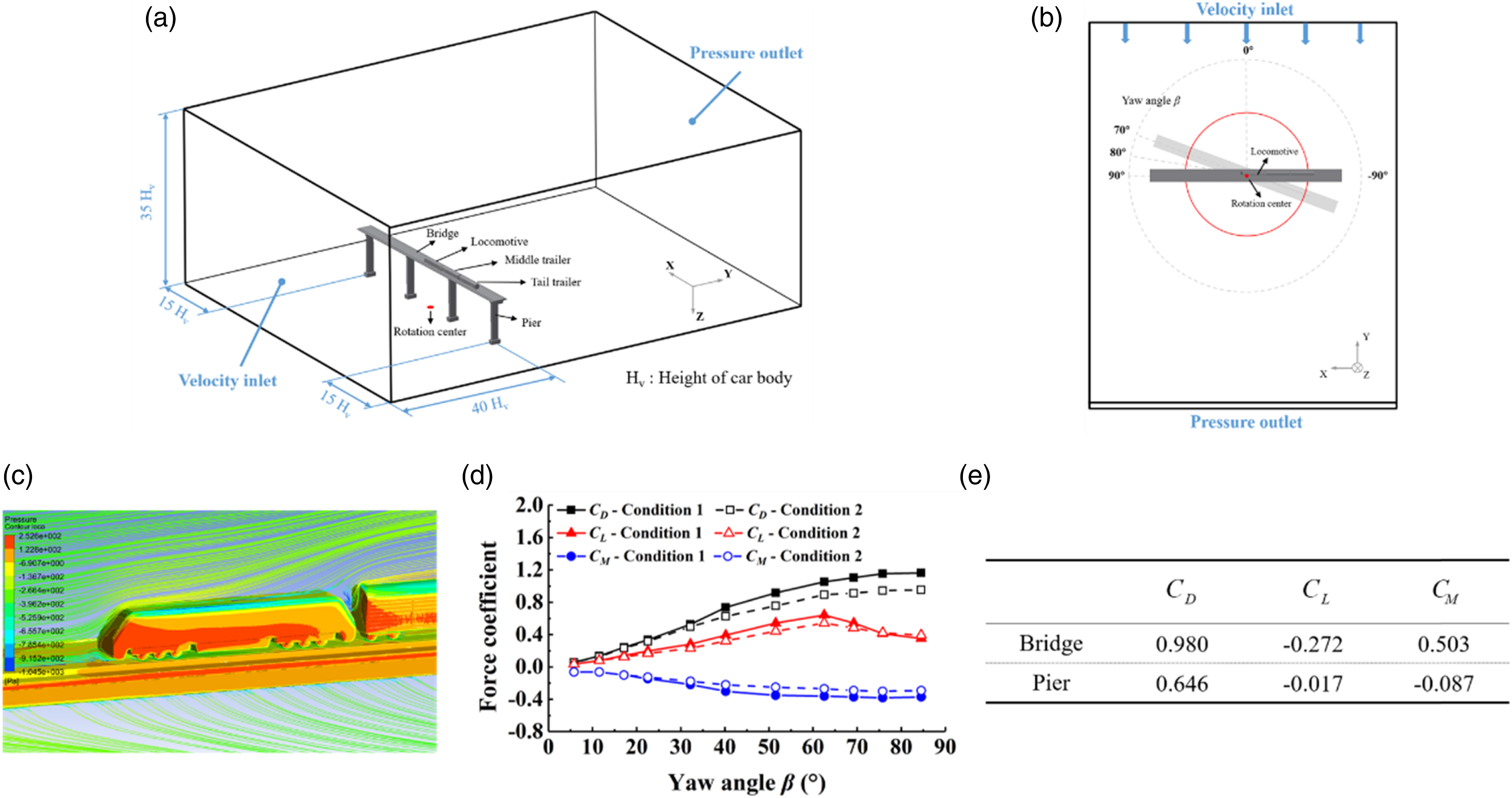
However, same calculation conditions as the wind tunnel tests were adopted for CFD simulation as well, and the meshing methods were defined based on the comparison of aerodynamic force coefficients between the wind tunnel test and CFD simulation results. In this study, ICEM (A toolbox within the ANSYS Workbench 18 ) was used to generate a hexahedral mesh around the vehicles with the smallest mesh size of 2 mm and six prism layers were applied to the vehicle boundary layer. The pressure distribution surrounding the locomotive and flow field are shown in Figure 6(c), and the aerodynamic force coefficient calculation results are shown in Figure 6(d) and (e). These results are combined with that of the wind tunnel tests, and aerodynamic force coefficients were used for the aerodynamic calculation of vehicles according to equations (11) and (12). As the test and calculation conditions were set with a yaw angle interval of 10° (Figure 6(b)) (R1-27), the force coefficients of the other yaw angles were approximated by linear interpolation based on the values of the two adjacent conditions.
Analysis of dynamic responses of the vehicle and bridge
Dynamic responses of the bridge
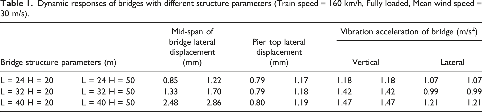
To ensure the safe operation of the train, the stability of the bridge should be the primary guarantee. However, due to the bridge vibration as well as the train operating conditions has direct relation to the span and pier height of the bridge, analysis of dynamic response of the bridge with different structural parameters during the express freight train crossing is of practical significance. In China, the span of simply supported girder railway bridges mainly includes 24, 32, and 40 m with a cross-section shown in Figure 1(d), 13 and the pier height ranges from 5 to 50 m. 29
Dynamic responses of bridges with different structure parameters (Train speed = 160 km/h, Fully loaded, Mean wind speed = 30 m/s).
Running safety of the express freight train
Evaluation criteria for the running safety of express freight vehicles.
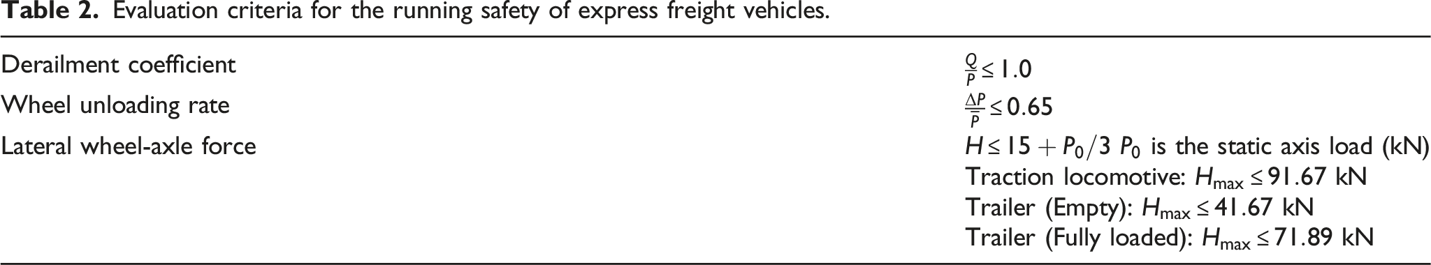
To evaluate the safety of express freight train, the dynamic responses of the vehicles in different positions are analysed as shown in Figure 7(a) and (b). For different axle loads, empty and fully loaded vehicles are considered separately. It can be seen that the values of derailment coefficient and wheel unloading rate of the trailers are larger than those of the locomotive, and the safety of the empty trailer is relatively worse under the influence of wind load owing to the light axle load. Although the lateral wheel-axle force of the locomotive is the largest, it is still far less than the limit value. However, the wheel unloading rate of the empty trailer in the middle position was 0.61, which is close to the limit value of 0.65. Therefore, for an express freight train, the trailers in the middle position have the highest operational risk than locomotives, which can be regarded as the calculation objective and basis of train speed safety domain. However, this is different from the conclusions in the researches on high-speed railway vehicles32–34 and special consideration should be given to evaluating the safety of express freight trains. In addition, the safety of the vehicle on windward side track of the bridge is relatively poor, which may be due to the larger wind load acting on the car body as shown in Figure 5(d). Dynamic responses of express freight vehicles (a) Different positions of the train (b) Running conditions on the bridge (Train speed = 160 km/h Mean wind speed = 20 m/s).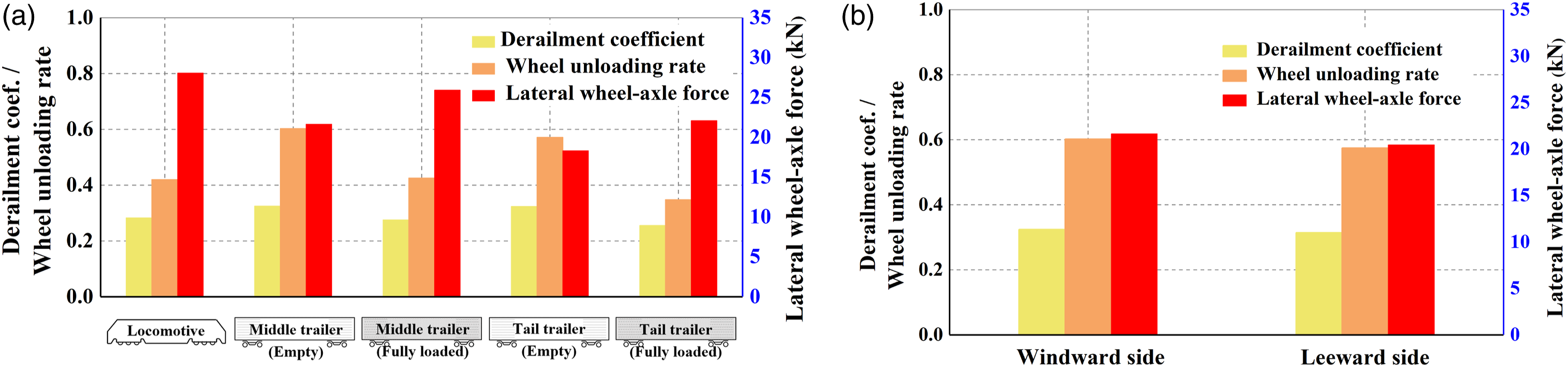
The primary objective of this study is to analyse the relationship between maximum wind speed that the train can withstand and maximum speed at which the train can run under safe conditions. Figure 8(a) and (b) indicate that the wheel unloading rate and derailment coefficient increase significantly under the action of wind load, especially the side force and rolling moment, when compared with no-wind condition. The maximum value of wheel unloading rate under unsteady wind speed Vehicle responses under different wind speed conditions (a) Derailment coefficient (b) Wheel unloading rate (Train speed = 160 km/h).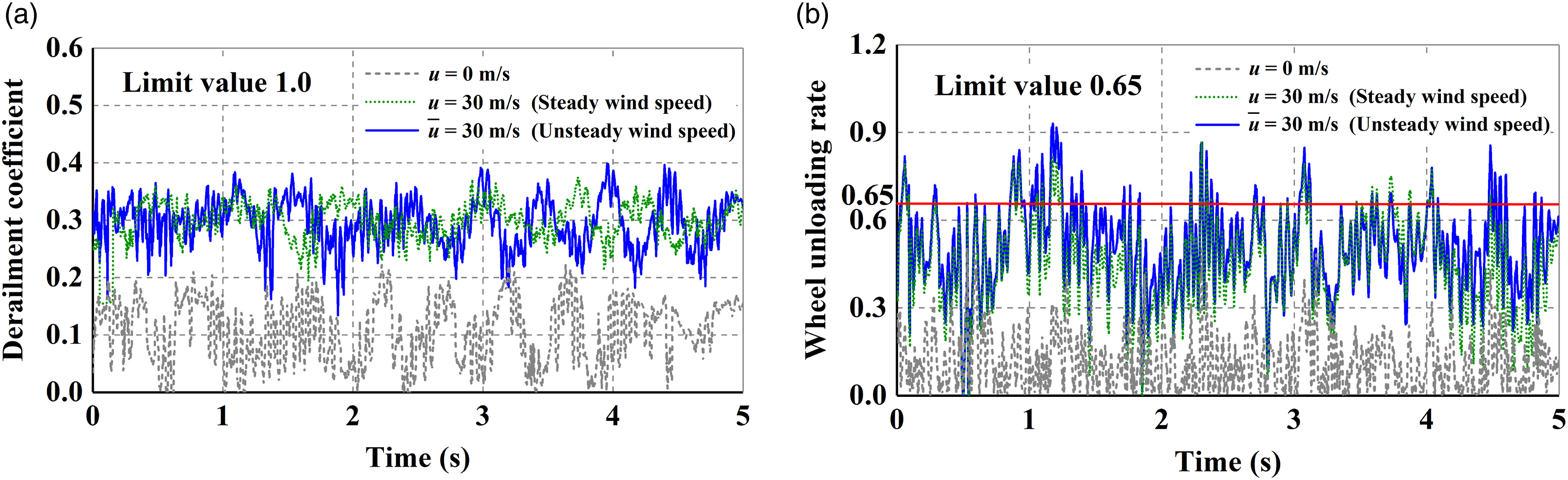
In addition, according to the results in Figure 9(a)–(c), the fluctuation and stochasticity of the fluctuating wind speed have a certain influence on the vehicle responses, and the safety criteria under unsteady wind loads are larger than those under steady wind loads. The differences in wheel unloading rate between the unsteady and steady wind loads were 4–8% and those of the derailment coefficient were 3–5%, which indicates that the risk of derailment is higher under the influence of unsteady wind load. Effect of wind and train speeds on the safety criteria (empty trailer) (a) Derailment coefficient (b) Wheel unloading rate (c) Lateral wheel-axle force.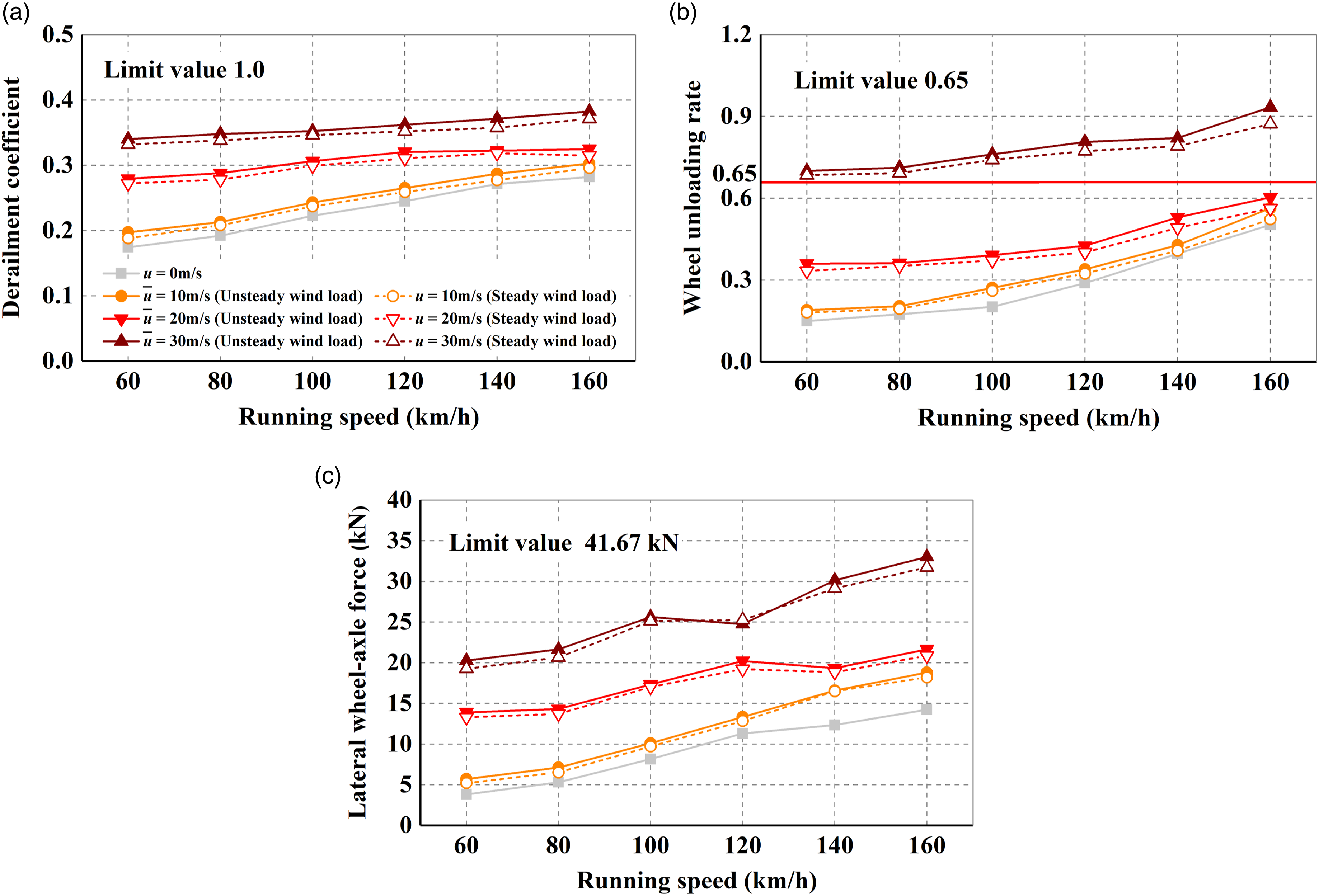
Moreover, all the safety criteria increased with the wind and train speeds; however, wheel unloading rate was the most sensitive to wind speed. Although the variation trends of derailment coefficient and lateral wheel-axle force are similar to that of wheel unloading rate, they are still less than the prescribed limit. Therefore, wheel unloading rate is the most critical criterion for restricting the train speed and should be used to define the boundary between safe and unsafe zones.
When the mean wind speed reached 30 m/s, the wheel unloading rate exceeded the limit for all train speed conditions. However, the windward side wheel detached from the rail when the mean wind speed was 34.0 m/s as shown in Figure 10(a) and (b). In this circumstance, the wheel-rail relative lateral displacement of the leeward side wheel reaches the maximum value close to the wheel flange, and vertical wheel-rail force of the windward side wheel drops to 0 and lasts for more than 0.08 s, which indicates the extreme scenario of derailment during strong crosswind. Wheel-rail interaction in the extreme scenario of derailment (a) Wheel unloading rate of the windward wheel (b) Wheel–rail relative lateral displacement of the leeward wheel (Train speed = 160 km/h, Mean wind speed = 34.0 m/s).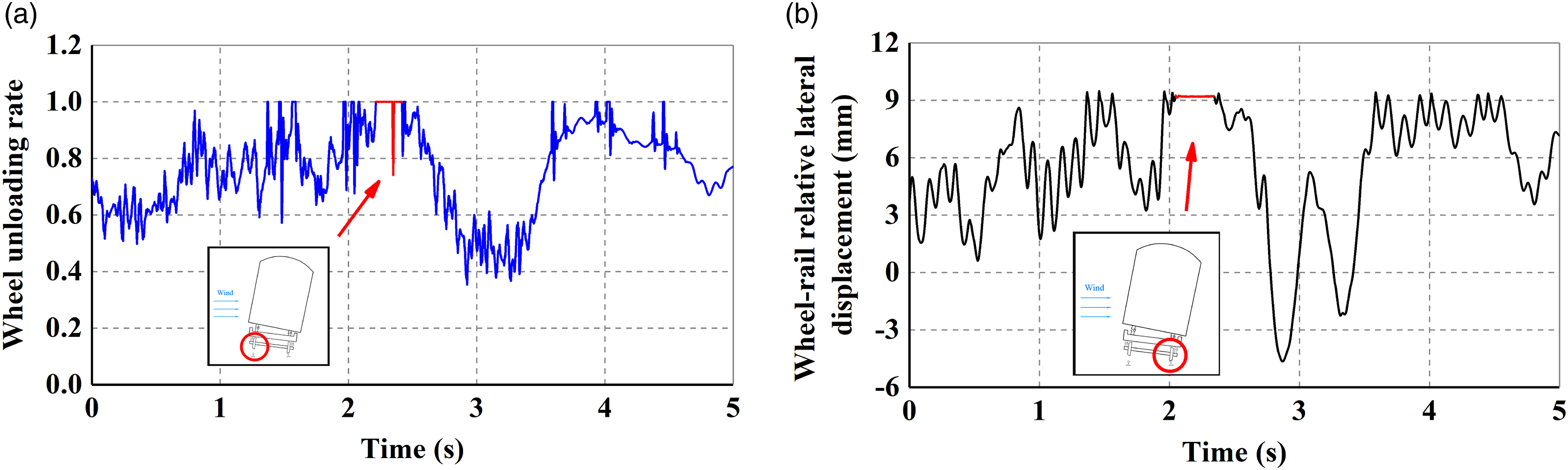
Safety criteria when the train runs over the bridges with different spans (Pier height 20 m).
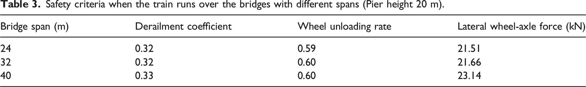
Figure 11(a) presents the relation between pier height and safety criteria based on the train conditions specified previously. The results show that running safety is worse when the train runs over a bridge with higher piers. In order to clarify the reason for the influence of pier height on the running safety of the train, the ratio of wheel unloading rate between the vehicle on the bridge with 50 and 10 m pier height in various terrain categories is shown in Figure 11(b). The vertical profile indices of mean wind speed (a) Vehicle responses when the train runs over bridges with different pier heights (Span 32 m); (b) Effect of terrain category on the wheel unloading rate between bridges with high and low piers (Train speed = 160 km/h).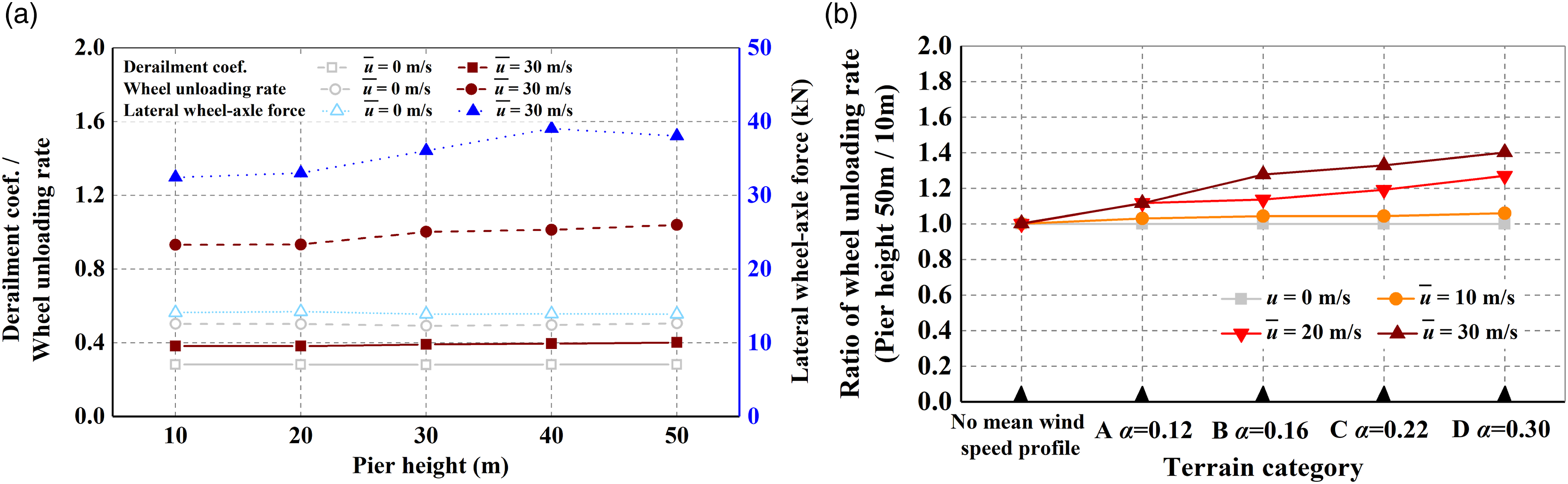
However, Figure 11(b) also indicates that if the vertical wind speed profile is not considered, namely the mean wind speeds at the height of the bridge deck with high and low piers are equal, the ratio of wheel unloading rate between high and low piers is approximately 1. This means that if the wind loads on the bridge and vehicle were equal (the difference of crosswind load on the pier is small, which can be ignored), structural rigidity of the bridges with different pier heights has negligible influence on the running safety, and the running safety is more sensitive to the wind load directly acting on the train. This behaviour can be explained by the fact that the lateral displacement of the deck caused by the wind load on the bridge and the train moving load can be easily followed due to the wheel-rail interaction force.
Based on the above analysis, it can be concluded that the wind speed limit should be adjusted and improved according to the pier height of the bridge and terrain category. If the bridge is located in an area with a large profile index such as a city with dense buildings, the wind speed limit should be appropriately reduced, and it is not suitable for erecting high-pier bridges in this area. In addition, wind barriers can be installed on the side of the bridge deck to reduce the risk of accidents during crosswind.
Wind and train speed limits for safe operation
The running safety of express freight trains can be evaluated by analysing the wind and train speed limits that the vehicle can withstand before exceeding some of the safety criteria limits. Based on the analysis in Section 4.2, the wheel unloading rate should be considered as the restricted criterion to define the boundary between safe and unsafe zones for each combination of train and wind speeds.
Figure 12(a) and (b) present the wind and train speed limits for safe operation of an express freight train. The figures indicate that train safety is dependent on both the train and wind speeds and wind speed limit decreases with an increase in the train speed. In addition, for a lower wind speed at the reference height, express freight trains can operate at a maximum design speed of 160 km/h. When the mean wind speed is greater than 22.7 m/s, the train must be restricted in speed and prohibited from entering the bridge when reaching 28.3 m/s. Thus, these diagrams are an intuitive tool that can be used as a reference to define the speed limits for express freight trains depending on the crosswind conditions. Diagrams of running safety domain (a) Wind speed limit (b) Train speed limit (Span = 32 m Pier height = 20 m) (c) Wind speed limits for bridges with different pier heights (Train speed = 160 km/h).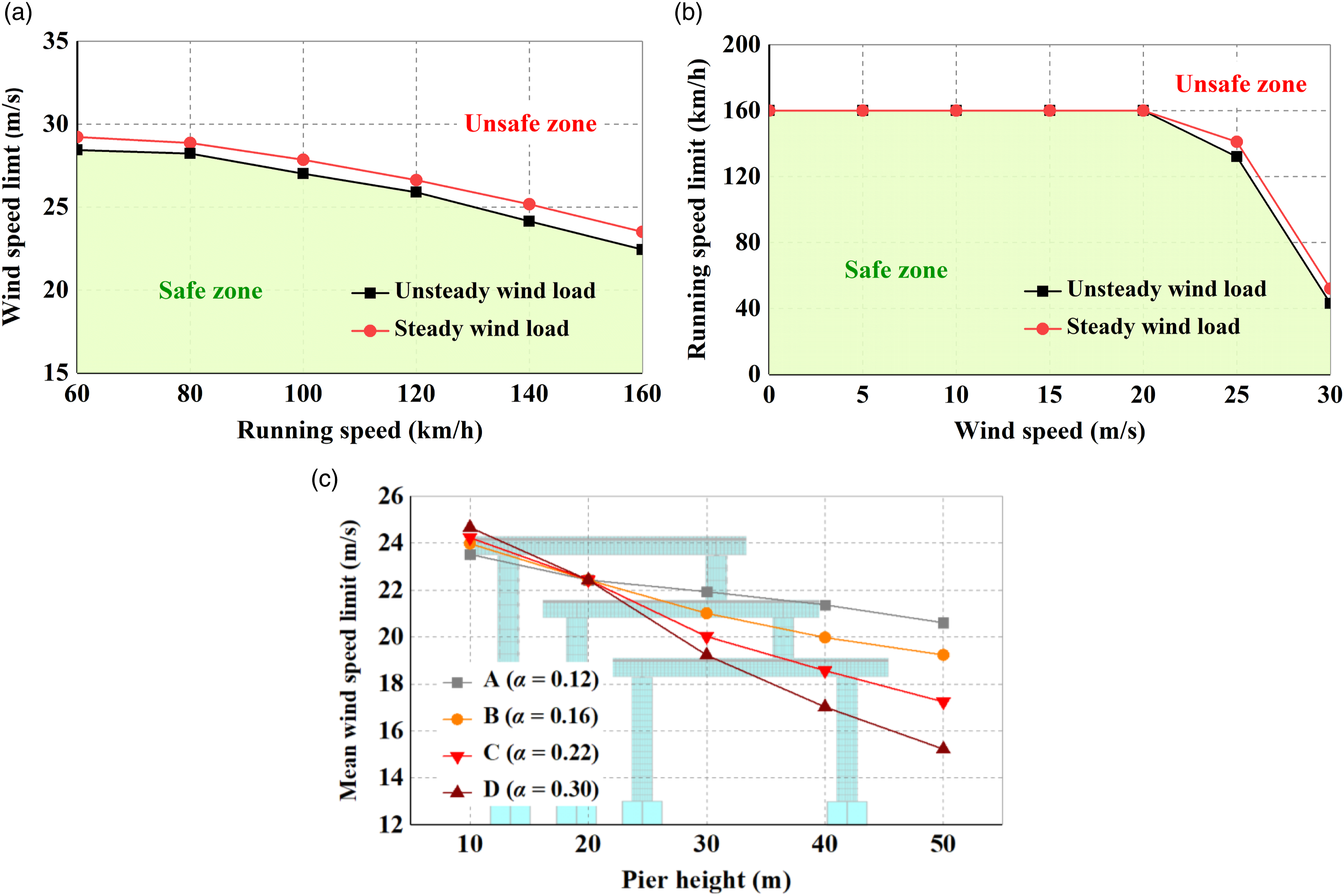
Many recent studies have adopted a steady wind load to evaluate the running safety of trains.35,36 The safety domain in Figure 12(a) and (b) shows that both the wind and train speed limits under the action of unsteady wind load are lower than those under steady wind load. This illustrates that it would be more secure to evaluate the safety of express freight trains when considering the effect of unsteady wind loads and the traditional method can be modified appropriately.
Considering the effect of pier height on the running safety of express freight trains, Figure 12(c) shows the relationship between wind speed limit and pier height in different terrain categories. It was observed that the influence of pier height on the evaluation of running safety cannot be ignored. For instance, in type A category, the mean wind speed limit for a bridge with a pier height of 10 m is 23.5 m/s at the reference height whereas it reduces to 20.8 m/s for a pier height of 50 m; the difference is 11.5%. Moreover, this effect is more pronounced as the mean wind speed profile index
Conclusions
In this study, we investigated the running safety of express freight trains in crosswind running over a simply supported girder railway bridge by establishing a vehicle-track-bridge coupling system. The dynamic responses of the bridge and vehicle were analysed in detail and the wind and train speed limits for safe operation were presented. In addition, the relationship between the running safety and the structural parameters of bridge was analysed and reasonable suggestions for the operation of express freight trains were proposed. The major conclusions of this study can be summarised as follows: 1. The vertical vibration of the bridge with a larger span is stronger and lateral displacement of the higher-pier bridge under the influence of wind load and train moving load is more intense than that of the low-pier bridge. However, dynamic responses of bridges with different structure parameters are all less than the limit values of bridge stability. 2. In terms of train responses, all the safety criteria of the vehicles increased with the wind and train speeds, and the wheel unloading rate was most sensitive to the wind speed. For an express freight train, the trailers in the middle position had the highest operational risk compared to the locomotive. In addition, the running safety of the vehicle under unsteady wind speed were lower than that under steady wind speed under the action of buffeting wind load. 3. When the mean wind speed was less than 22.7 m/s, the express freight train can operate at a maximum design speed of 160 km/h and it must be prohibited from entering the bridge when reaching 28.3 m/s. An extreme derailment scenario may occur when the mean wind speed reaches 34.0 m/s. 4. The running safety was more sensitive to wind load directly acting on the train compared with the influence of structural rigidity of bridges with different pier heights. Because high piers result in higher wind speed on the deck owing to the existence of mean wind speed vertical profile, the wind speed limit should be properly adjusted and improved according to the pier height and terrain category.
However, this study mainly focuses on the running condition of single-track. The dynamic behaviour of express freight vehicles under train-passing running over a bridge will be further investigated in the future.
Footnotes
Declaration of conflicting interests
The author(s) declared no potential conflicts of interest with respect to the research, authorship, and/or publication of this article.
Funding
The author(s) disclosed receipt of the following financial support for the research, authorship, and/or publication of this article: This study was supported by the National Key R&D Program of China (No. 2017YFB1201302-12A).