
Abstract
Secondary suspensions play an essential role in the dynamic behaviour of rail vehicles. In particular, they are adopted to reduce the vibrations transmitted to the carbody, thus improving ride comfort. In this paper, an experimental characterization of the viscous damper and coil spring elements composing a vertical secondary suspension is presented. The elements are separately tested with the aim of analysing their dynamic behaviour. Then, modified prototypes are manufactured to reduce the transmitted force. The results of the experimental campaign are later adopted to tune the parameters of the mathematical model of the whole secondary suspension, including the dynamics of both the coil spring and the damper elements. This model allows discussing the effectiveness of the proposed modifications, proving the design of both the components to be fundamental for the improvement of ride comfort.
Keywords
Introduction
In recent years, innovation in the railway industry has made railway transportation more and more competitive in the field of mobility. The significant increase in service speeds fostered the demand for railway transportation. Thus, customer requirements and expectations during the journey make ride comfort one of the most relevant issues for railway operators. 1 High level of ride comfort not only provides a healthier and more pleasant journey for the passenger, but reduces the mechanical stress and consequent wear of the vehicle’s components. In fact, vibrations induced by track irregularity significantly excite all the components along the transmission path from the wheel/rail interface to the carbody. As a result, relevant low frequency vibrations may arise inside the coach, negatively affecting passenger perception.
To cope with these vibrations and to guarantee a high level of ride comfort and running safety, passenger trains are equipped with two stages of suspension systems. The primary one significantly reduces the vibration amplitude and frequency content to ensure the stability of the vehicle; the secondary stage is more oriented towards passenger comfort mitigation. 2 Mathematical models of the secondary suspensions are typically adopted to investigate the vibration transmissibility and to improve passenger comfort. 3 Various modelling approaches can be adopted depending on the degree of accuracy required, ranging from traditional passive systems to semi-active and active ones. Passive suspensions have been widely adopted and still nowadays represent a valuable solution. In this framework, studies have been carried out to identify the damping of the secondary suspension system that best isolates the vibrations transmitted to the carbody. 4 The possibility of optimising the characteristics of a secondary suspension passive damper has been experimentally assessed. 5 A damper with a reduced damping characteristic and a saturation of the maximum force transmissible was designed. This solution proved to ensure good damping properties at low frequency and to significantly reduce the force transmitted to the carbody at high frequency. An in-depth study concerning different suspension system layouts was carried out. 6 An effective way to minimize coil spring resonance excitation by means of a pivot arm has been investigated.
The operating conditions of an in-service vehicle typically influence the performance of the suspension system, the characteristics of passive elements being constant in terms of frequency and vibration amplitude. For these reasons, researchers’ attention has been focused on the design and control of active secondary suspension systems where the performance vary along with running dynamics.7–10 As regards technologies that are widely diffused within the railway network, it is worth mentioning the air spring adopted as a secondary suspension system. Made of an air inflated cushion, the spring’s stiffness can be effectively varied, improving passenger comfort. 11
The majority of the research work done in this field relates to ideal subsystems. Accounting for the dynamics of the components was found to be a key requirement to prevent the designed solution being ineffective when installed on a railway vehicle. 12 The performance of an active secondary suspension system, including actuator dynamics, was also discussed. 13
In this context, the target of improving the railway vehicle’s dynamic response is addressed in this paper from the perspective of modelling the dynamic response of a passive secondary suspension system, while optimising the characteristics of both the vertical spring and damper. To this end, reference is made to a traditional high-speed vehicle, equipped with coil springs and hydraulic dampers as secondary suspension elements. Starting from the characterization of the components installed on a commercial vehicle, laboratory prototypes of new solutions are realized, with the aim of improving the dynamic response. From the technological point of view, these solutions represent a first attempt to fulfil the proposed task, and are not meant to be directly installed on the vehicle. In that case, an extended homologation process should be implemented, including among the others in-line tests, fatigue tests etc.
In detail, this paper is organized as follows. At first, the experimental characterisation of the damper and spring elements of the secondary suspension is proposed respectively in terms of hysteresis cycles and Frequency Response Function (FRF). Secondly, the secondary suspension model is presented, and model parameters are identified from the experimental data. In the first place, attention is paid to the damper and coil spring elements, analysing the blocked transfer stiffness of the single components; then, the whole suspension system is considered, and the dynamic response of different suspension configurations are evaluated numerically. Finally, conclusions are drawn from the analyses performed.
Experimental characterization of the secondary suspension elements
To improve the dynamic behaviour of the whole secondary suspension system, the characteristics of both the hydraulic damper and the coil spring should be optimised. Although a change in the characteristics of just one component can result in beneficial effects on the dynamics of the whole system, better results are expected by modifying the damper and the spring simultaneously. Indeed, the two components act in parallel, thus the overall transmitted force consists of the sum of the contribution of each single component.
Concerning with high-speed applications, two solutions are typically adopted to design the secondary suspensions, namely coil and air springs. In this paper, reference is made to a high-speed vehicle running along the Italian network, whose vertical secondary suspension is composed by the parallel of two traditional coil springs and a damper. To characterize its dynamic behaviour, an experimental campaign on the components of the secondary suspension system physically installed on the vehicle was arranged. The tests involved one single damper and spring component, for which two prototypes with different characteristics were considered and tested.
Vertical damper
In order to experimentally characterize the damper component, a dedicated test bench was designed as shown in Figure 1. The standard damper prototype was installed in the vertical direction according to the proper mounting configuration, with the bottom end clamped and the top end connected to a hydraulic actuator. Characterisation of the damper. The bottom end was clamped and the top end was connected to a hydraulic actuator.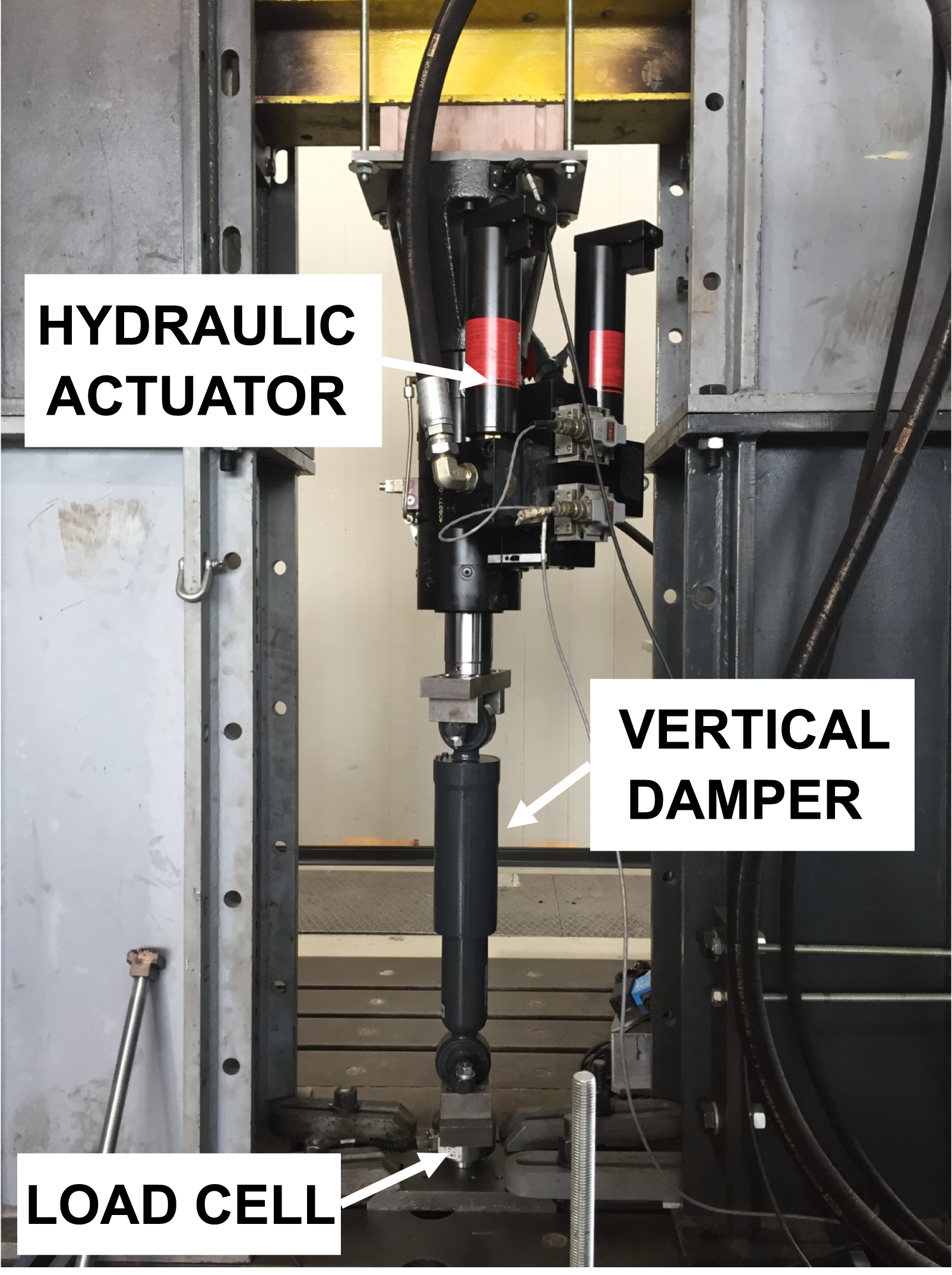
The effect of the dampers is generally detrimental at high frequency, where these components transmit a significant amount of force. For this reason, a modified version of the component was realized. At the design stage, the attention was paid to the effect associated to carbody vibration modes. 5 The proposed solution aims at limiting the force transmission at frequencies higher than 3 Hz, while it is expected to provide similar performance in the frequency range interested by the carbody rigid motions (bounce and pitch natural frequencies typically occur at frequency around 1 Hz). 14 More in detail, particular attention was given to the stiffness of the mount bushings. From a manufacturing point of view, the mount bushings are components whose stiffness can be easily modified by changing the material they are made of. To accomplish the task, soft mounting bushings were adopted, so that a reduced-stiffness device was preferred to a purely dissipative component.
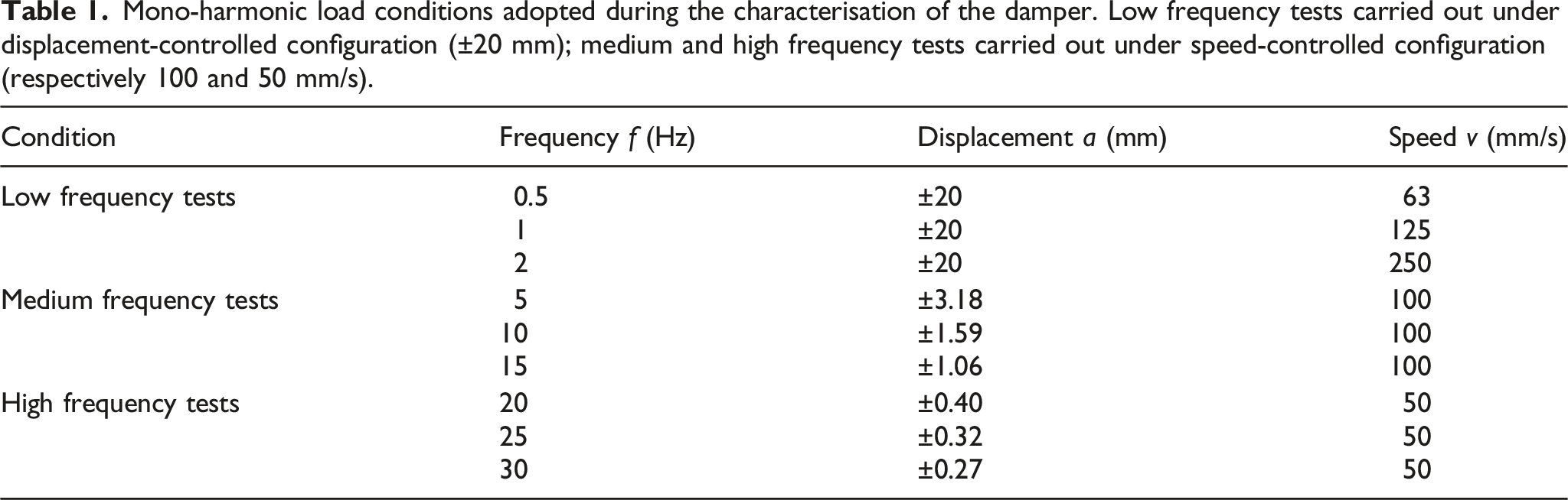
Mono-harmonic load conditions adopted during the characterisation of the damper. Low frequency tests carried out under displacement-controlled configuration (±20 mm); medium and high frequency tests carried out under speed-controlled configuration (respectively 100 and 50 mm/s).
In Figure 2, the results of the dampers experimental characterisation are proposed in terms of hysteresis cycles, showing the damper stroke along the x-axis and the corresponding force exerted along the y-axis. One test case per each of the conditions (low-medium-high frequency) reported in Table 1 has been considered. In the representation, the blue and red curves are respectively associated to the standard and modified (reduced bushing stiffness) prototypes. The standard prototype shows the typical behaviour of a purely dissipative element, with a regular and symmetric hysteresis cycle at 1 and 10 Hz (Figure 2(b) and (c)). A slightly different behaviour can be registered for increasing the frequency in Figure 2(c), associated to the viscoelastic oil contribution. On the other hand, the introduction of a soft bushing mount in series to the hydraulic damper introduces an elastic force contribution besides the dissipative one, that can be recognised by the slope of the red hysteresis cycles. In particular, the modified prototype shows a hysteresis cycle close to an ideal damper only at low frequency (1 Hz, Figure 2(a)). Conversely, at 10 and 25 Hz the small area inside the hysteresis cycle proves the reduced damping force: the component behaviour moves towards the one of an ideal spring. A reduction of the maximum force that changes from 3000 N to 1000 N at 10 Hz is also noticeable. Characterisation of the hydraulic damper. Hysteresis cycles of the standard and modified prototypes measured at (a) 1 Hz, (b) 10 Hz, (c) 25 Hz.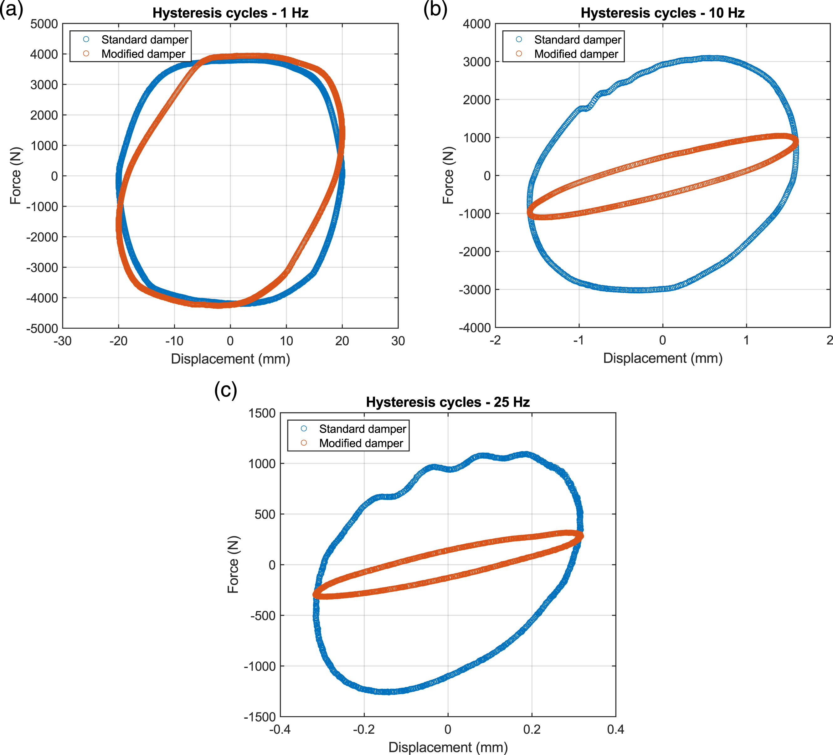
For the sake of completeness, it is worth mentioning that similar results have been achieved also for the other test cases listed in Table 1.
Coil spring
A further test campaign was setup to characterise the coil spring of the secondary suspension system installed on the railway vehicle taken as reference. Specifically, the standard version of the component is made up of three concentric spring elements, as shown in Figure 3(a). Considering the reference standard EN 13906-1,
15
the theoretical parameters of each spring can be computed. Their stiffnesses are estimated as 0.113, 0.083 and 0.049 MN/m respectively for the external, middle and inner spring. The 3-springs stiffness is therefore of 0.245 MN/m, that yields to a value of 0.98 MN/m per bogie (4 springs acting in parallel), which is close to the value of 1 MN/m of typical vertical secondary suspensions of high-speed trains. The standard
15
allows computing the expected natural frequencies of each coil spring, that turn out to be of 22.4, 25.3 and 27.5 Hz respectively for the external, middle and inner springs. These theoretical values will be later compared to the ones experimentally identified. Experimental characterisation of the coil springs. (a) Experimental setup: coil spring excited by means of a hydraulic actuator, (b) detail of the dissipative rubber element interposed between spring coils.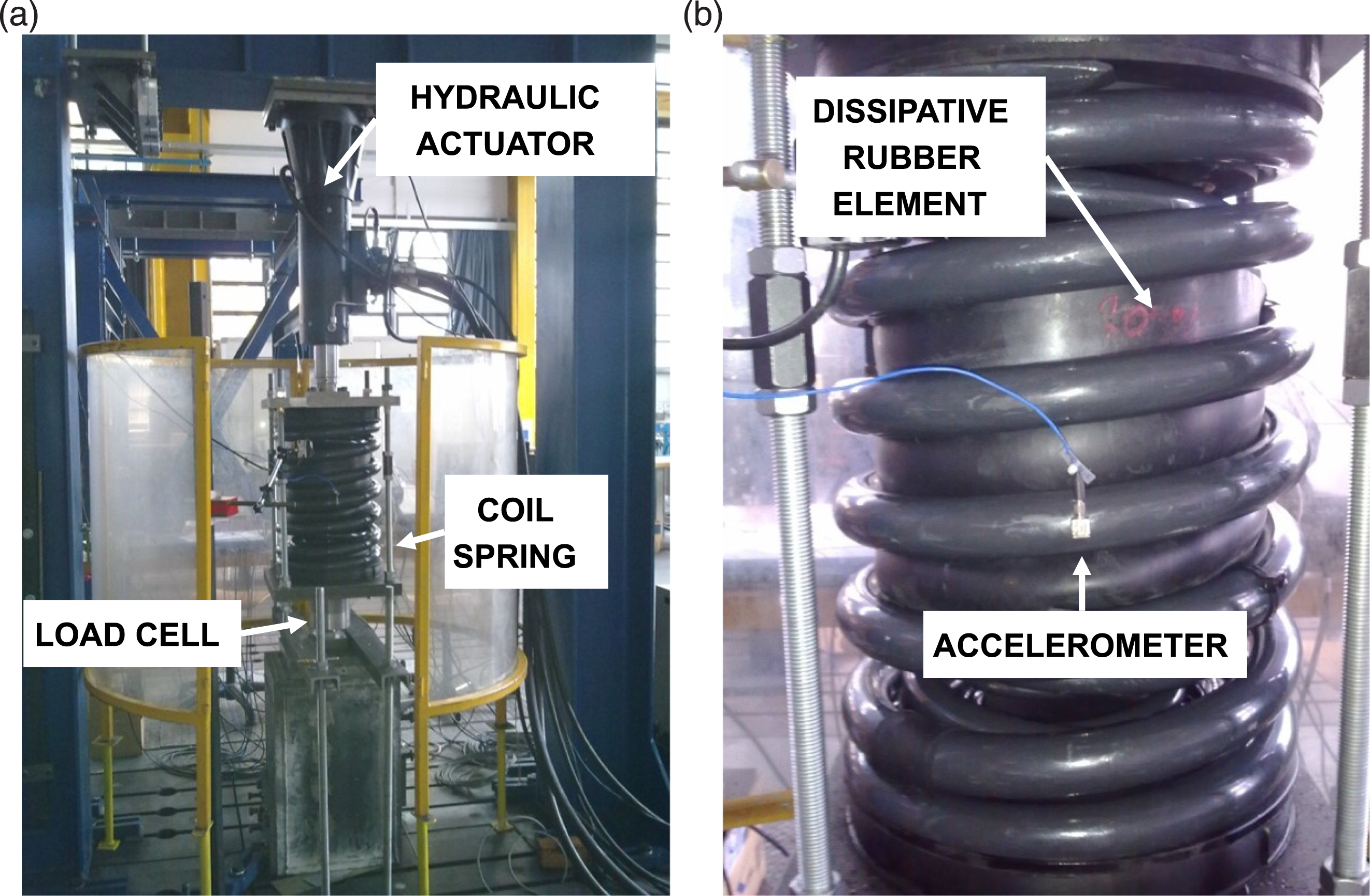
To improve the secondary suspension spring’s performance, a modified version of the component was realised too, aimed at mitigating the dynamic excitation that occurs on encountering the spring’s natural frequencies by increasing the damping contribution. Indeed, springs operating in frequency ranges near their natural frequencies may show poor performances, reducing the effectiveness of the suspension system. To this end, a reduction in the transmitted vibrations can be obtained by introducing dissipative rubber elements between the spring coils, thus increasing the component’s damping coefficient. This strategy was adopted to modify the standard spring element, as is visible in Figure 3(b). An experimental characterisation of both spring prototypes has been then arranged.
Regarding the test configuration, the bottom end of the spring was rigidly connected to the ground to reproduce the connection to the bogie frame. A load cell was installed in series to the component to measure the transmitted force. On the other hand, a hydraulic actuator was connected to the top end of the spring, where a static preload of 40 kN was applied to represent the vehicle’s weight. Three accelerometers have been glued at mid-span of each coil spring to measure the dynamic response of the system. The spring characterisation was carried out according to a closed loop control logic, by means of an imposed swept-sine displacement of constant amplitude of 0.05 mm, with a sweep rate of 0.05 Hz/s. Given the information about the theoretical natural frequencies of each coil spring, the dynamic response of the component was investigated in the 20–30 Hz frequency range. In the lower frequency range (0–20 Hz) a quasi-static behaviour of each spring element can be therefore expected. This assumption was also verified during a preliminary test campaign, where impact hammer tests were performed to assess the coil spring dynamics.
Concerning the characterisation of the coil springs, the FRFs relating the acceleration and the imposed displacement are shown in Figure 4. Each diagram refers to one of the concentric springs that make up the component, while blue and red curves respectively identify the standard and modified prototypes. Considering each diagram of Figure 4, a significant amplification of the measured acceleration can be observed in correspondence of the natural frequencies of each spring, at 24 Hz, 27.5 Hz and 29 Hz respectively for the external, middle and inner springs (blue lines, standard spring). Actually, other contributions can be observed especially in Figure 4(a), that may be associated to the 3D dynamics of the overall system. With respect to the theoretical values previously computed, a good degree of accuracy can be observed, with the experimental natural frequencies that are higher than the theoretical ones of about 1.5 Hz for each coil spring. Characterisation of the coil springs. FRFs between the acceleration and the imposed displacement of the standard and modified prototypes measured at (a) the external, (b) the middle and (c) the inner spring.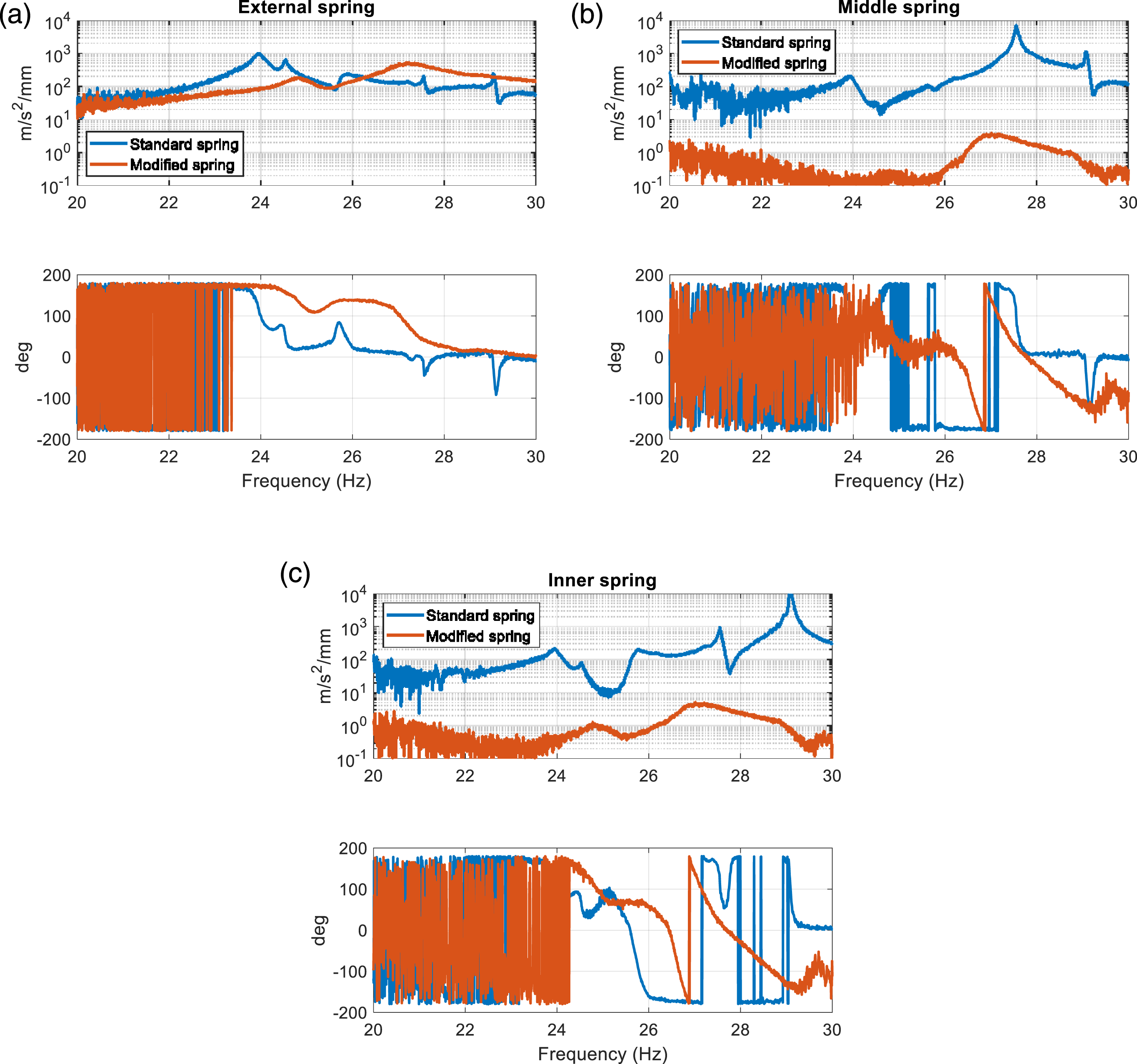
As for the modified prototype shown in red in Figure 4, the introduction of dissipative elements in between coils significantly affects the FRFs, given that the system is now dynamically coupled. Referring to Figure 4(a), an increase of the natural frequency from 24 to 25.5 Hz is observed, as well as a higher damping contribution, that is expected to efficiently filter out the force transmitted. In addition, a second resonance peak is observed nearby 27.5 Hz. This can be associated to a coupling effect between the external and middle springs due to the presence of the rubber element that connects them. Concerning the middle and inner springs in Figure 4(b) and (c), the effect of the modification is such that the corresponding resonance frequencies can be still observed at 25.5 and 27.5 Hz, while the peak at 29 Hz (Figure 4(c)) is almost completely cancelled.
Modelling of the secondary suspension
Based on the results of the experimental characterisation of the single components that make up the secondary suspension, in this section the lumped parameter models adopted to reproduce the vertical dynamics of a secondary suspension in the frequency range of 0–30 Hz are presented.
Single suspension elements
At first, attention is paid to the modelling strategy adopted to reproduce the single components that make up the suspension system. Specifically, Figure 5(a) and (b) respectively represent a single hydraulic damper and coil spring subsystem. The top ends of both the hydraulic damper and the coil spring are rigidly connected to the carbody (zc), whereas the lower ends are connected to the bogie frame (zb). Subsystems composing the model of the vertical secondary suspension. (a) Hydraulic damper, (b) coil spring.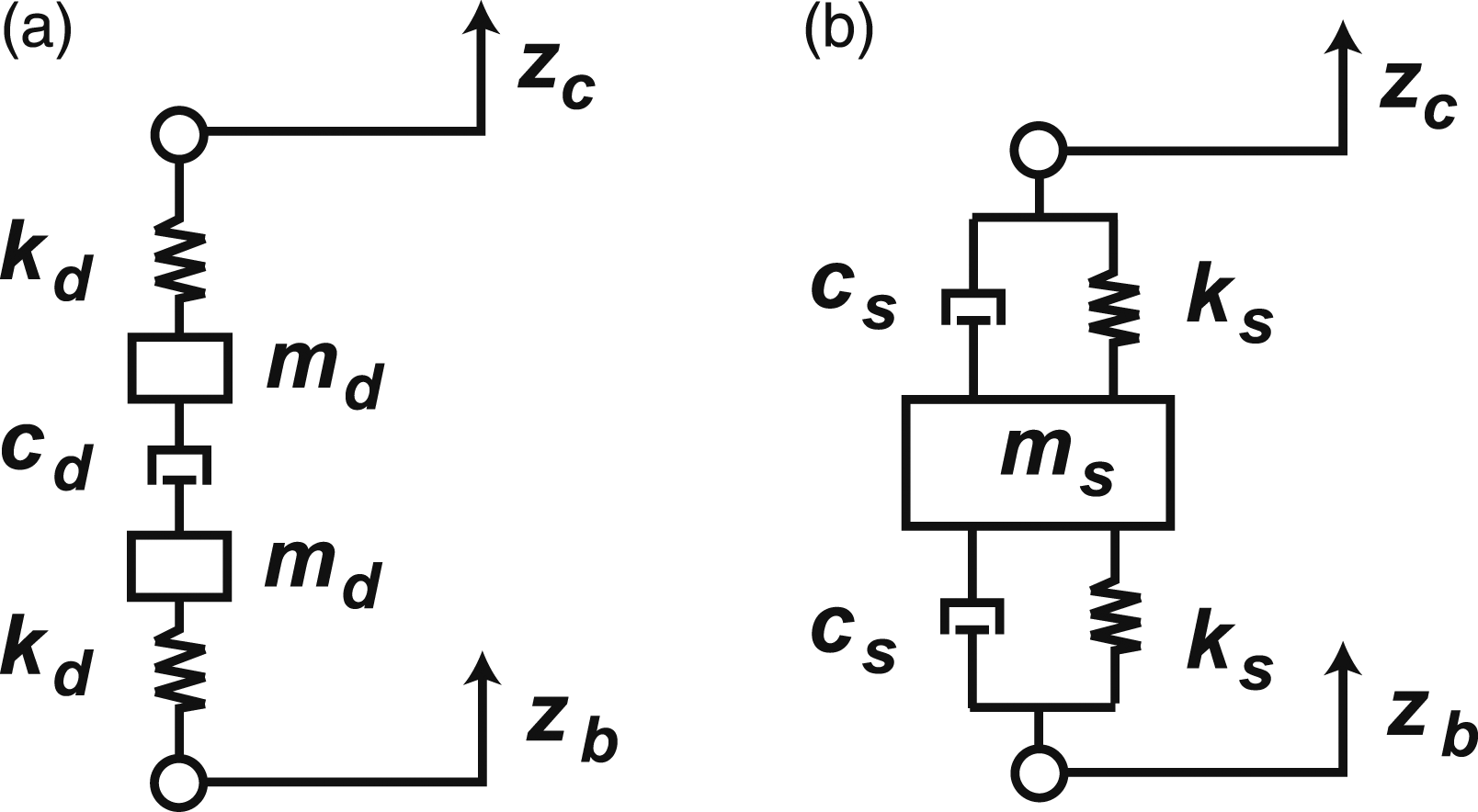
On the one hand, the hydraulic damper is modelled in the form of an ideal viscous damper, where the springs kd and the masses md represent the stiffness and the inertial properties of the mountings. On the other hand, coil springs are modelled as two pairs of ideal spring-dashpot (the latter being representative of a viscous damper), together with a mass ms included to reproduce the first mode of vibration of the subsystem.
This modelling choice was driven by the results of the experimental characterisation of the component, as it allows reproducing their dynamic response. In this respect, it is worth noting that the coil spring model reported in Figure 5(b) is suitable to reproduce only the first resonance mode. This choice comes as a compromise solution to be suitable both in case of standard and modified spring prototypes: in fact, in the frequency range under analysis, they respectively show three and one resonance peak when the blocked transfer stiffness (FRF defined as the ratio of force over displacement, see Figure 7) is considered. More refined modelling approaches, including higher order vibration modes, could be considered to improve the model accuracy although the proposed model still allows carrying out a comparative analysis between the two spring solutions.
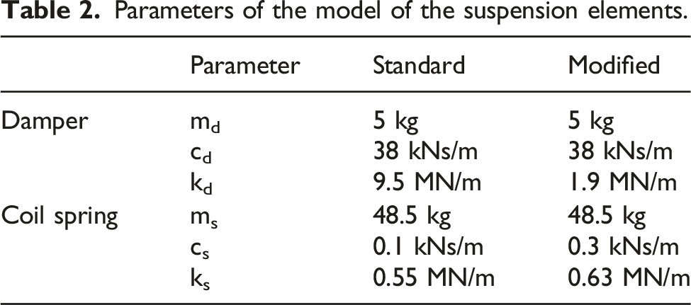
In Figure 6, the results of the dampers experimental characterisation (coloured solid lines) are compared with the numerical results obtained adopting the damper model of Figure 5(a), reported as dashed and dotted lines. The curve of an ideal damper is also reported as a continuous black line. The results are presented in terms of blocked transfer stiffness, that is the transfer function that represents the ratio between the force exerted by the component and the corresponding imposed vertical displacement, when the carbody side is fixed. To comply with the test characteristics described in Table 1, experimental data was connected by solid lines representing same test conditions (i.e., low, medium and high frequency tests). For both damper prototypes, model parameters were identified based on the best fit of the corresponding experimental data, reported in Table 2. A significant reduction of the stiffness kd is observed when comparing the two prototypes (passing from 9.5 MN/m to 1.9 MN/m), which complies with the introduction of a softer bushing mount. If reference is made to the experimental results of Figure 2(a), a maximum force of 4000 N is registered at low frequency, that would result in a deformation of about 2 mm in the case of the modified damper. This deformation of the rubber element, as well as the linear behaviour in the deformation range, should be investigated in detail at the industrialization stage of the proposed solution. For completeness, note that no variations of the other model parameters reported in Table 2 are implied. Characterisation of the hydraulic damper. The experimental blocked transfer stiffness and the numerical results are represented to compared. Parameters of the model of the suspension elements.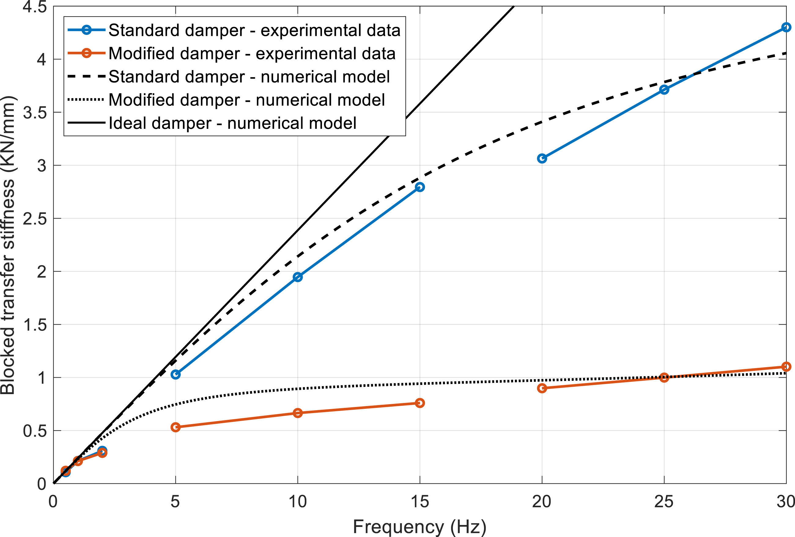
The results presented in Figure 6 show that the numerical model correctly reproduces the overall trend of the blocked transfer stiffness. On increasing the frequency, both solutions show an increase of the damper transfer stiffness, on account of the oil elastic contribution, as previously observed in research activities concerning damper elements. 5 As a result, a significant amount of energy is expected to excite the carbody flexible modes. 16 Thus, a desirable requirement is that of reducing the transfer stiffness as much as possible. To this end, the comparison of the experimental data of the two damper prototypes shows a significant improvement of the modified damper’s performance, especially in the 5–30 Hz frequency range. For example, a reduction of 50% is observed at 5 Hz, whereas a fourfold decrease is observed around 30 Hz. For the sake of completeness, note that no significant variations are observed in the low frequency range of 1–2 Hz, where the damper contribution is required to efficiently suppress the vertical rigid motions of the carbody. 14
On the other hand, localised differences can be identified when comparing the numerical and experimental curves. Even though the dynamics of the component could be accounted for with more refined modelling approaches to improve accuracy, the proposed modelling strategy is accurate enough to deepen knowledge of the influence of the suspension’s components. This is even more clear if reference is made to the transfer stiffness of a purely damper element, where a linear dependency with frequency can be observed (solid black line in Figure 6).
Focusing the attention to the spring element, the comparison between the experimental and numerical results are reported in Figure 7 in terms of blocked transfer stiffness, that relates the force exerted by the spring and the displacement imposed by the actuator, keeping the carbody end fixed. The blue and red lines are respectively associated to the experimental characterization of the standard and modified springs. Dashed and dotted lines represent the blocked transfer stiffness obtained as a best fit of the experimental curves, adopting the model of Figure 5(b). Characterisation of the coil springs. The experimental blocked transfer stiffness and the numerical results are represented and compared.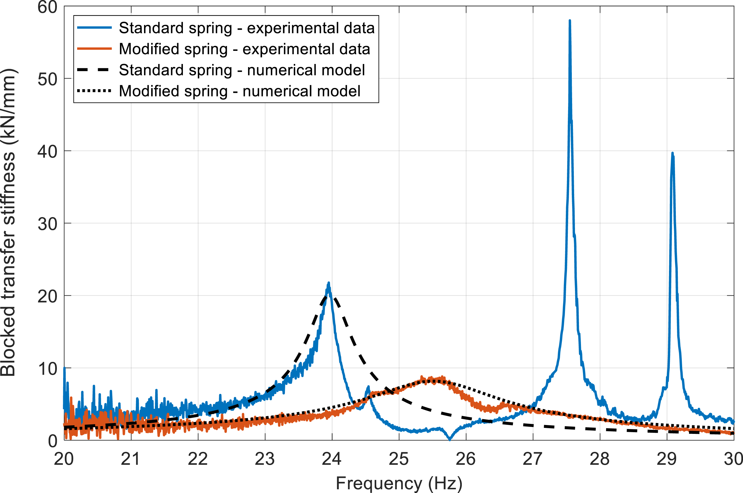
Considering the experimental data, the three concentric springs that make up the standard element significantly contribute to the overall response. In fact, three resonance peaks can be identified at 24, 27.5 and 29 Hz, each one respectively associated with the component’s external, middle, and inner spring as previously shown in Figure 4. Regarding the modified spring (red line), a unique resonance peak is observed. The resonance excitation is slightly shifted towards a higher frequency of 25.5 Hz, compared to 24 Hz for the standard element. In this respect, it is here recalled that the FRF presented in Figure 4 (acceleration over displacement) shows two resonances for the modified spring, with the major one appearing at 27.5 Hz. When the transfer stiffness of Figure 7 (force over displacement) is instead considered, this peak is significantly reduced in amplitude. The experimental result of Figure 7 thus suggests the possibility to model the spring dynamic response as that of a 1 d.o.f. system.
As expected, the higher damping contribution induced by the rubber components between coils leads to a relevant decrease in the amplitude of the frequency response. For instance, a twofold, sixfold and fourfold decrease is registered when observing the modified spring resonance peaks. A remarkable decrease in the transfer stiffness can be also noticed, thus proving the proposed solution to be suitable for vibrations isolation.
Despite the performances observed, it is worth mentioning that from a practical point of view, issues may arise in terms of spring maintenance, as visual inspections of the inner coil would be prevented by this solution. In this respect, it is here recalled that the modified spring prototype aims at demonstrating the effectiveness of the proposed solution, that is to increase the damping contribution of the coil spring. Similar results can be achieved considering different technical solutions, for instance including friction dampers as those installed on Over-Head Transmission Lines, that would still preserve the visual inspection of the component.
The attention is now paid to the comparison of the experimental and numerical results. Referring to the standard spring prototype, experimental data is well fitted up to the system’s first natural frequency associated to the external coil spring. If the modified spring is considered, in the 20–30 Hz frequency range a significantly higher degree of accuracy can be registered by comparing numerical and experimental data.
As previously discussed while commenting Figure 5(a) and (b), a single degree of freedom system was considered for modelling the spring, restricting attention to the first resonance only. Thus, the simplified spring model adopted does not make it possible to reproduce higher order resonances, and so the system’s dynamics is expected to be underestimated at higher frequencies, especially in the neighbourhood of the other natural frequencies. This represent a limitation of the proposed model, that could be solved including higher order vibration modes following a model update. However, this work aims at comparing the performance of the standard and modified prototypes, to verify the effectiveness of the proposed solution towards the mitigation of the resonance excitation. In this respect, the simplified modelling strategy is still capable of pursuing the task, limiting the analysis to the first resonance mode that occurs at 24 and 25.5 Hz, respectively for the standard and modified prototypes.
In Table 2 the model parameters adopted for both spring prototypes are summarized. Given the nominal value of the stiffness ks of the standard coil spring element, the equivalent mass ms and damping coefficient cs were evaluated to match the frequency response measured around the first natural frequency. The same procedure has been repeated for the modified prototype, assuming a constant value for the equivalent mass ms. Since an increase of the first natural frequency of the modified spring is observed, a slight increase of the stiffness ks is obtained. It can be also observed that the introduction of rubber elements between coils leads to an increase of the damping parameter cs.
Full secondary suspension model
Once the characterisation of the single components was completed, the whole secondary suspension model was introduced to evaluate the blocked transfer stiffness of the whole system. To respect the arrangement of the considered railway vehicle (Figure 8(a)), the model is realized as the parallel of two spring subsystems and one damper element, as shown in Figure 8(b). Modelling of the whole secondary suspension. (a) Secondary suspension system of the reference railway vehicle, (b) modelling strategy adopted.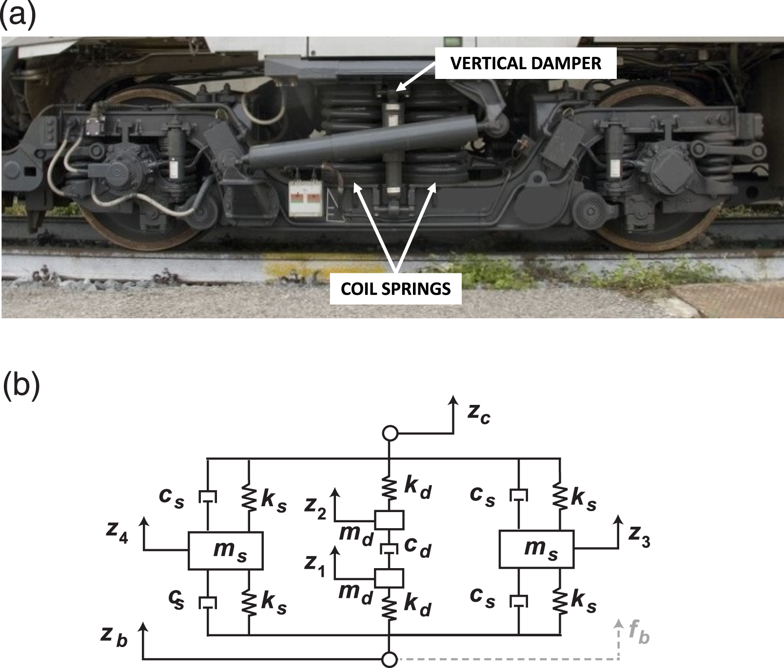
By assembling the vertical displacements of all the components (the independent coordinates) highlighted in Figure 8(b) in the vector z = [z1 z2 z3 z4 zc zb]T, the equation of motion of the system can be described according to the set of ordinary differential equations: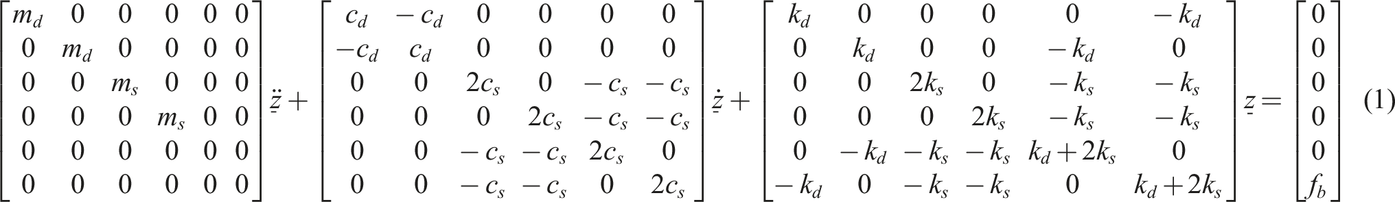
where fb represents the equivalent external force applied in correspondence of the bogie connection.
In this work, the performance of the suspension system is evaluated in the frequency domain in terms of blocked transfer stiffness, computed by constraining the top end of the system in correspondence of the carbody connection (zc = 0) and computing the Fourier Transform of the active d.o.f. zb, together with the external load fb. Thus, the blocked transfer stiffness of the suspension system can be computed as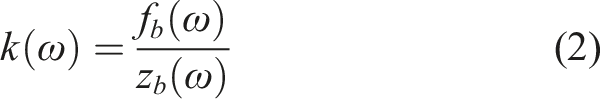
The dynamic response of the secondary suspension model is presented in Figure 9, where the simulation results are shown in terms of suspension blocked transfer stiffness in the frequency range of interest (0–30 Hz). A comparison between the possible combinations of standard and modified components (configurations A to D) is reported. Blocked transfer stiffness of different configurations of secondary suspensions.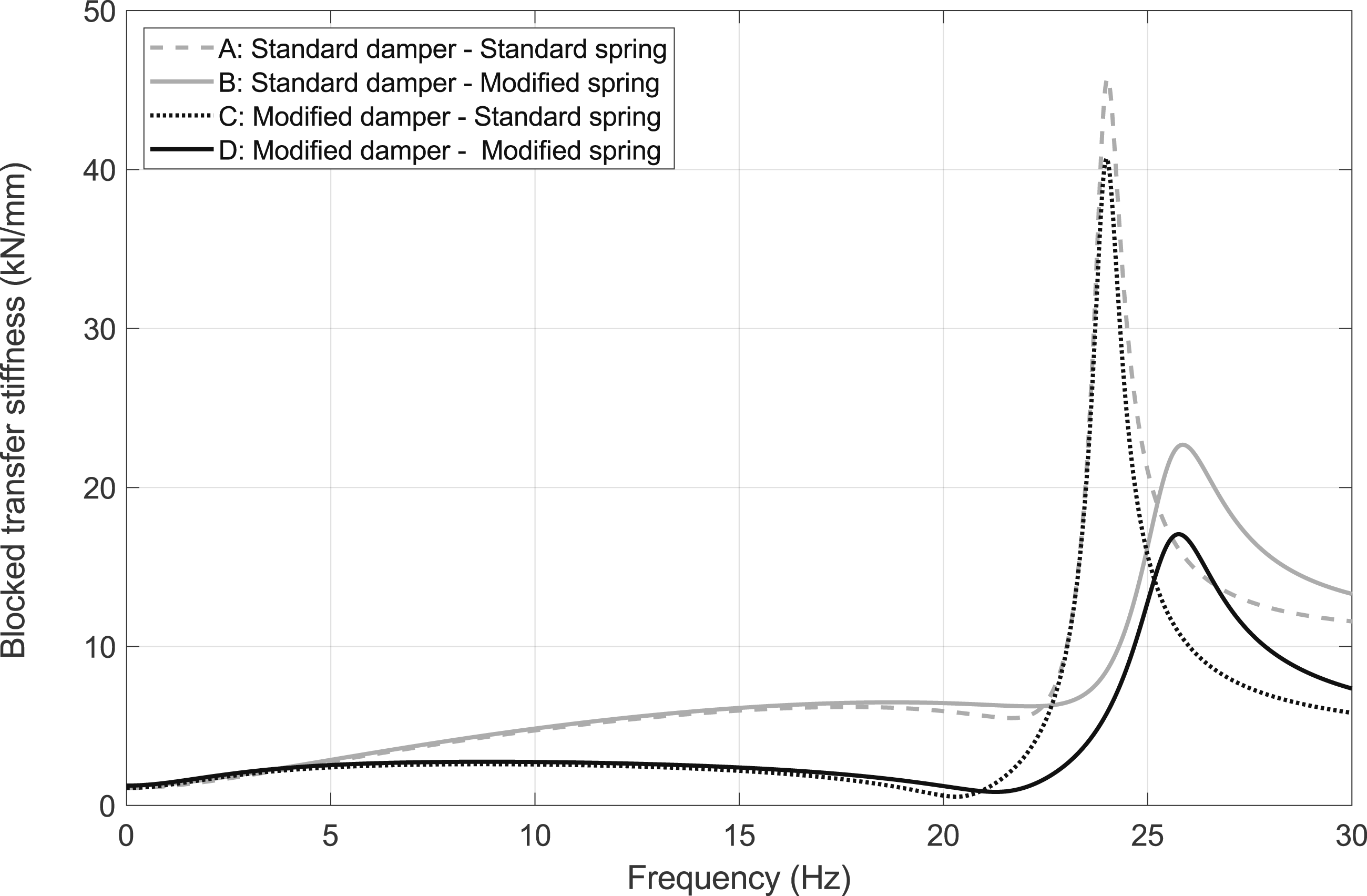
First, a description of the typical dynamic behaviour of the suspension can be addressed considering configuration A (standard spring - standard damper). One single resonance peak can be observed in correspondence of the spring’s first natural frequency.
Configuration A proves that the main issue concerning the standard suspension is related to the strong amplification of the transfer stiffness around 24 Hz. In this frequency range, the coil springs’ first resonance has a detrimental effect on the overall system’s response. To reduce the vibration transmitted to the carbody at high frequency, a significant improvement can be achieved by introducing rubber elements to the spring (configuration B). This strategy leads to lower amplification due to the increased damping of the component. In this case, the transfer stiffness peak is also shifted to approximately 25.5 Hz, which corresponds to the natural frequency of the modified springs.
While the new spring characteristics (configuration B) show an improvement to the suspension’s performance around 20–30 Hz, in other frequency ranges no significant differences can be noted, as the system’s response is dominated by the characteristics of the hydraulic damper. As proof of this, the transfer stiffness obtained by combining the standard spring and the modified damper can be considered (configuration C). By reducing the stiffness of the hydraulic damper bushing, a considerable reduction in the transfer stiffness was achieved in the 0–20 Hz frequency range.
Even though the optimisation of a single component of the suspension system (configurations B and C) leads to an improvement compared to the initial suspension arrangement (configuration A), better results can be achieved by optimising the parameters of the whole suspension simultaneously. If reference is made to configuration D, obtained by combining the effect of the modified damper and the modified spring, the transfer stiffness shows the best results over the whole frequency range considered for the analysis.
As a final remark, a comment can be made referring to the effect of the coil spring resonance excitation. Experimental results prove the natural frequency to typically belong to the frequency range considered for the analysis. Specifically, this represents a detrimental effect as it results in dynamic amplifications that may significantly excite the vibrations modes of the carbody (floor and inner elements). In this respect, the reference standard for ride comfort evaluation (EN 12299 1 ) defines weighting functions to account for the human body filtering effect: for instance, vertical acceleration levels are reduced by 3 dB at 20 Hz. As a result, the effect of the flexible modes excitation from the coil resonance spring will be mitigated, but may still represent a concern from ride comfort viewpoint depending on the dynamic amplification introduced by the resonance excitation. Therefore, a desired requirement could be that of increasing the coil spring resonance, limiting the coupling effect with carbody modes in the related frequency range.
Conclusions
This paper defines a passive secondary suspension model that accounts for the dynamic behaviour of its components. An experimental characterisation of both spring and damper was conducted to identify model parameters. Possible guidelines to improve the design of the suspension were identified and applied to existing components. Thus, optimised prototypes were realized, aimed at reducing the transfer stiffness of the components and consequent force transmitted. Based on the experimental data, a comparative analysis of the prototypes was carried out to highlight the benefits resulting from the proposed solution. Concerning the damper, soft bushings prove to significantly reduce the force transmitted by the component while operating. As for the spring, the introduction of rubber elements in between coils lead to the spring natural frequencies being damped.
In addition, the performance of the whole suspension system composed of the parallel of two springs and damper elements was evaluated. Simulations demonstrated that the best results are obtained when the damper and the springs are optimized simultaneously. If this is the case, the trend of the transfer stiffness shows all the benefits introduced by the single components at the same time.
To conclude, the proposed suspension model together with the experimentally identified parameters could be integrated into a full railway vehicle model for ride comfort evaluation. This way, the dynamic behaviour of the suspension system could be assessed considering the whole elements of the vibration transmission path, from wheel/rail contact up to the carbody floor. As a future application, following a technical design of the solutions, the possibility to carry out endurance tests of both the modified spring and damper subsystems could be considered, as well as specific in-line tests. This way, the possible mitigating solutions could be verified considering the vehicle operating conditions.
Footnotes
Declaration of conflicting interests
The author(s) declared no potential conflicts of interest with respect to the research, authorship, and/or publication of this article.
Funding
The author(s) received no financial support for the research, authorship, and/or publication of this article.