
Abstract
Hyperloop, a very high-speed transportation system including a pod transporting the passengers in a tube, forms the core debate in numerous recent investigations. The present paper, furthering the current advanced findings, proposes a novel hybrid levitation including Electro-Dynamic Suspension (EDS) and air cushions for the pod in the hyperloop system. It also presents a vibrational model for the hybrid levitation pod to predict the vibration behavior of the pod in accelerating and braking maneuvers. In this regard, an industrial pod is designed conceptually by performing preliminary calculations. Via CFD simulations in Ansys Fluent software, we hold forth a nonlinear dynamic model for the air cushions. Then, the paper analyzes a 3-DOF vibration model of the pod and verifies it by comparing the related results with obtained ones from the MSc ADAMS software. Afterward, the mentioned vibration model is developed into a 7-DOF model to predict the vibration behavior of the pod in accelerating and braking maneuvers. Also, the governing dynamic equations of the system are derived and numerically solved. Finally, the vibration behavior of the pod in different accelerating and braking conditions is investigated.
Introduction
Transportation and using appropriate vehicles to get to a destination as quickly as possible always have been crucial issues for humans throughout history. In late 2013, Elon Musk proposed the Hyperloop Transportation Technology (HTT), an ultra-high-speed passenger or cargo transportation system known as the fifth generation of transport. 1 The operation mechanism of these systems is the movement of a high-speed capsule-shaped vehicle, called the pod, inside tubes with approximately vacuum air conditions. The pod with an axial compressor is accelerated using the Linear Induction Motor (LIM) 1 ; however, some other researchers do not employ any fan and motor compressor in their proposed design. 2 Two different technologies are suspending the pod; magnetic levitation and air cushions. Also, three magnetic suspension systems exist operating magnetic levitation technology (e.g., High-Speed Trains: HST) that are: Electro Magnetic Suspension (EMS), Electro Dynamic Suspension (EDS), and Inductrack.3–5 EMS systems work based on the attractive influence of the magnets between guideways and the body. The EDS vehicles select the repulsive properties for levitating the system.4,6,7 Inductrack is another case of EDS type wherein used a passive suspension system. Instead of superconductive magnets, it employs Permanent Magnets (PM) in the Halbach arrays form.8–10 In some other pod designs, air cushions cause the pod to float. Such systems mainly use the axial compressor to intake the air and lead it to the air cushions.1,11–13
Some research investigated presenting the appropriate dynamic modeling of HST considering acceleration and braking effects. Wei et al. investigated the longitudinal and vertical dynamics of an HST rescued by locomotives during braking on grades. 14 Zhang et al. designed a PM eddy current brake and analyzed its braking effect on the levitation characteristics of an HTS maglev vehicle. 15 Suo et al. presented the acceleration and deceleration model of HST using an air gun and magnetic braking devices. 16 Powell and Palacin studied the maximum allowable longitudinal acceleration for keeping passenger stability in moving railway vehicles. 17 Ju and Lin numerically analyzed vehicle–bridge vibration responses by considering vehicle braking and acceleration using a seven DOF half-vehicle model. 18
Some other researchers dedicated their studies to calculating lift and drag forces and the stiffness and damping of different kinds of levitations of HST. Zhu et al. calculated the damping and stiffness of maglev systems in terms of oscillation frequency using an experimental method. 19 Wright and Bird proposed an analytical approach calculating the damping and stiffness of a 4-DOF electrodynamic wheel maglev vehicle. 20 Liu and Chen studied the EMS lift force of maglev vehicles at low and medium speeds with a theoretical formula and simulation in software. 21 Post and Ryutov presented simple analytical relations for calculating the drag and lift forces of the inductrack levitation systems.8–10 Cai et al. investigated the lift and guidance forces of maglev trains in analytical and experimental methods.22–24
Some research presents appropriate dynamic models for Air Cushion Vehicles (ACV) using analytical, numerical, or experimental approaches. Hovercraft is one of the most common ACVs that uses air cushion technology. Yun and Bliaut presented a simplified relation for calculating rigid air cushion pressure in the hovercraft system. 25 Pavăl et al. numerically investigated air movement inside the inner cavity of the air cushion of a hovercraft system using Ansys Fluent software. For that, the air cushion was simulated to obtain air inlet velocities and lift force in different gaps. 26 Other models also were proposed for the cushion.27–29
In little investigations, scholars tried to design the system and present dynamic models for the hyperloop. Indraneel et al. designed an experimentally magnetic brake and levitation system for the hyperloop pod.30,31 Pradhan and Katyayan created a pod called “OrcaPod” with the inductrack levitation kind and analyzed its free vibrations behavior assuming OrcaPod with a four DOF half-vehicle model. 32 Using the Root Locus method, Galluzzi et al. analyzed the stability of a small pod equipped with electrodynamic levitation in the hyperloop system. The lift and drag forces and the natural frequencies were analytically calculated.33,34 Lim et al. designed a model of null-flux coil EDS for the hyperloop system. 7 Madhan et al. designed a wheeled pod for the hyperloop system and proposed a nine DOF vibration model with six angled magnetic modules. 35
According to the research conducted so far, all the mentioned references assumed the pod with maglev technology, and using the air cushions for these systems has not been investigated yet. Hence, the present paper introduces a novel hybrid levitation for the pod in the hyperloop system. The air cushions are responsible for supporting the pod weight. The paper proposes EDS to counteract the dynamic loads, improve the dynamic motions, and provide acceleration and braking of the pod. Also, a dynamic model is presented for the pod with hybrid levitation to predict the pod’s behavior in accelerating and braking maneuvers.
Preliminary calculations and pod design
As mentioned earlier, the proposed pod simultaneously has magnetic and air cushion suspensions as a hybrid levitation. Therefore, before designing and presenting the chosen pod, it is necessary to perform preliminary calculations to determine the number of air cushions required to overcome the pod’s overall weight. The proposed pod weight is calculated as approximately 26,000 kg. The designed pod with its components is presented later with more explanations. In this regard, the pod will suspend when the lift force of air cushions used in the system can overcome the total weight of the pod. The outlet air pressure under the pad from each cushion is estimated at approximately
The proposed pod model is presented based on the performed initial calculations. The suggested conceptual pod is designed in SolidWorks and shown as follows:
According to Figure 1, the designed pod is equipped with 20 air cushions. In addition, two pairs of magnets with inductrack suspension kind are located at the rear and front of the pod, which are responsible for controlling the dynamic deflections as well as the braking and acceleration of the pod. When the pod moves inside the tube, the compressor intakes the tube air into the vehicle leading to the air cushions and causing the pod to suspend. The proposed designed pod model along with its components in SolidWorks ((a) isometric (b) front (c) side view).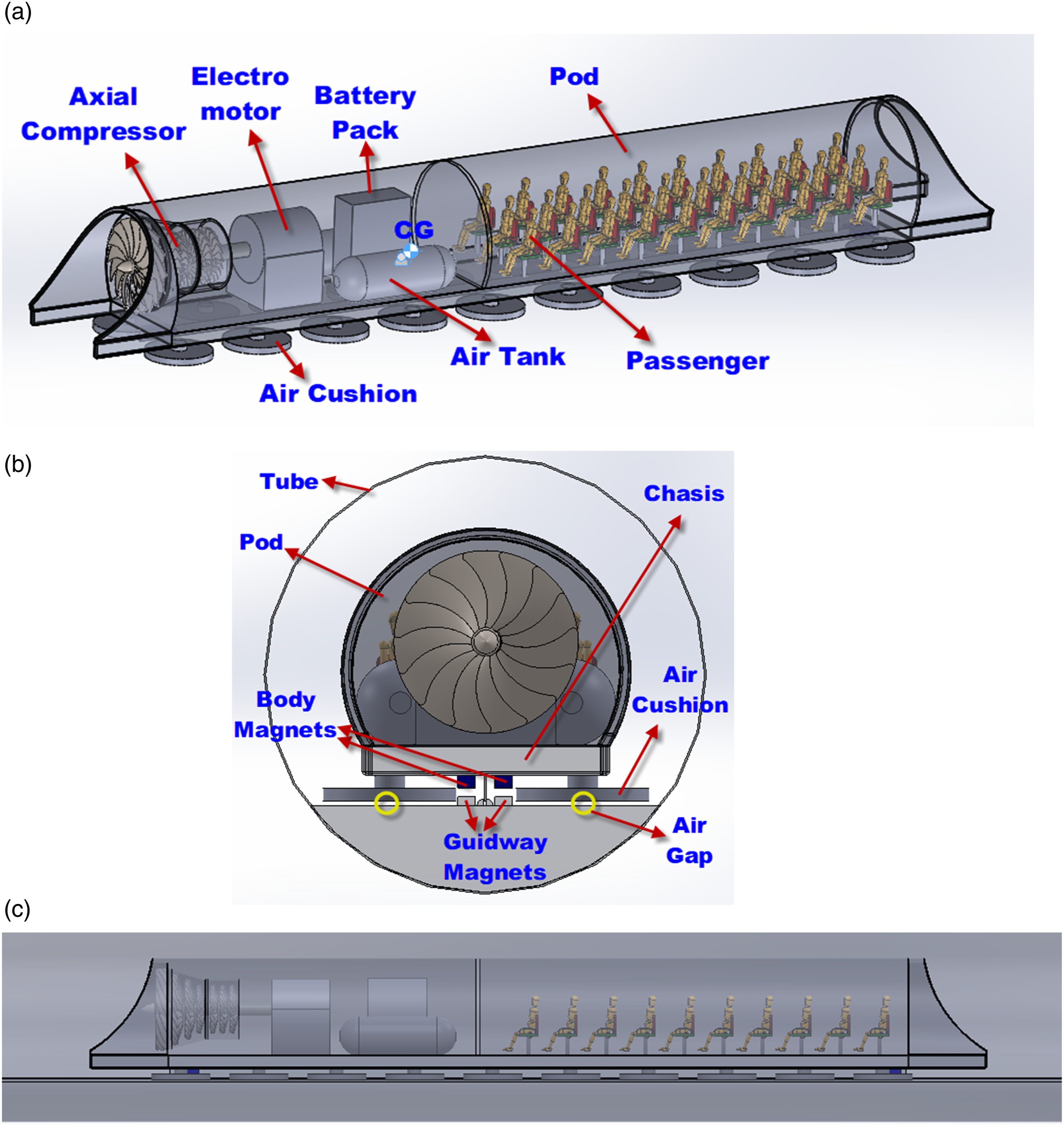
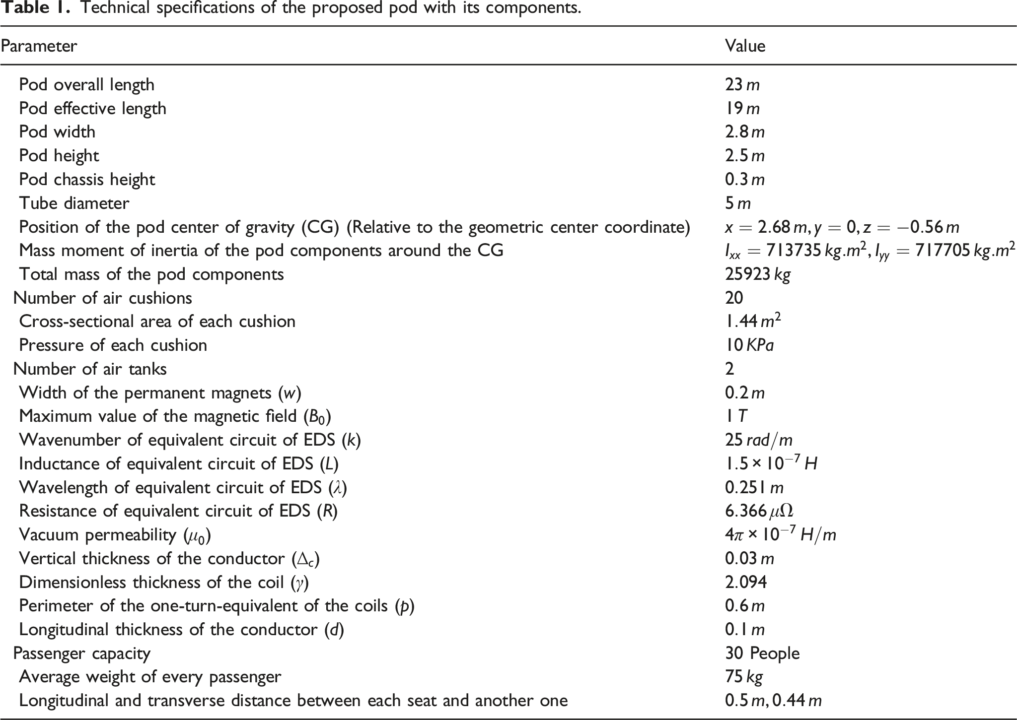
Technical specifications of the proposed pod with its components.
To further investigate and understand the air cushion levitation mechanism, the air cushion modeling used in the paper is explained in the next section in more detail.
Nonlinear dynamic modeling of the air cushions
Before examining the dynamic modeling of the system, it is necessary to determine the model of air cushions used in the pod. Therefore, in this section, the air cushions modeling is described. The proposed model is a circular shape pattern with the specified dimensions as follows:
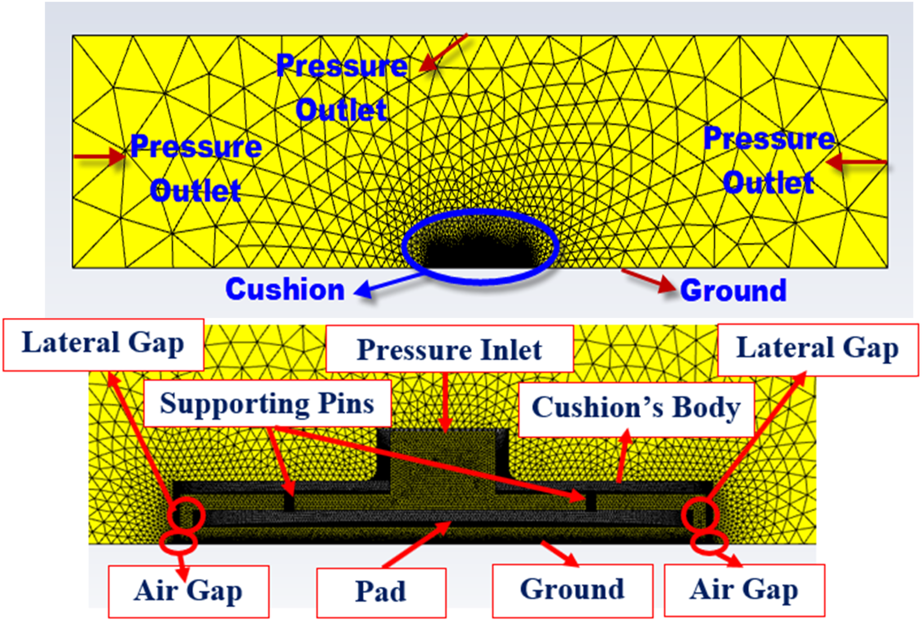
According to Figure 2, a circular air cushion is designed with the specific geometric dimensions in Solidworks. The system consists of an inlet channel for the airflow passage and a circular bottom plate connected to the body via four supporting pins. In this regard, airflow leaves the system through the lateral gap between the plate and the cushion body. The formation of air vortices and reaction forces under the cushion plate cause the lift force to the cushion. The work given here shows designing different air cushion shapes in Solidworks, including equilateral triangle, circle, ellipse, rectangle, square, and four other combined shapes, including circle-rectangle and circle-square (known as oval shapes), hexagonal, and fillet square with two different radii. Then, the Computational Fluid Dynamics (CFD) of each designed cushion is analyzed under the same simulation conditions using Ansys Fluent software. To create the same condition in simulating the airflow inside each air cushion, the cross-sectional area of all cushions’ bottom plate (or pad) is chosen equal. Also, the remaining other geometric parameters are assumed equal. The simulation input parameters are the inlet pressure of the airflow into the cushion inlet channel and the air gap between the cushion and the ground surface. Then the simulation output is the air cushion lift force. The meshing and governing boundary conditions for simulating airflow into the system, as well as the cushion components, can be seen in Figure 3 as follows: Circular air cushion modeling and its dimensions. Meshing symmetry plane of the cushion and governing boundary conditions.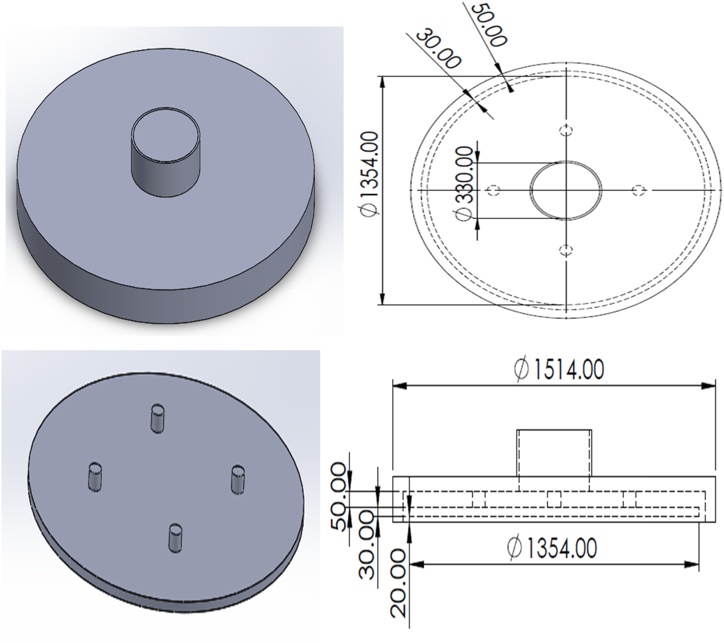
Note, by considering Elon Musk’s report, the inlet air pressure to the pod is
After performing the simulations and comparing the results, it is concluded that the air cushion with a circular geometry pattern provides the highest lift force compared to other geometric shapes in the same simulation conditions. For this reason, a circular pattern is used in this study. Finally, using the curve fitting method, the paper presents a new approximate mathematical formula for calculating the lift force in terms of parameters, including the inlet pressure and air gap as follows:
where
In the next section, the dynamic modeling of the proposed pod is presented with a 3-DOF vibrational model, and the governing equations of motion are obtained to analyze its vibrational behavior.
The 3-DOF vibration model of the pod
Previously, the paper described the initial design calculations and presented air cushions dynamic modeling. In this section, a three Degree of Freedom (DOF) vibration model is proposed for the pod. Furthermore, the related governing equations are derived and verified by comparing the calculated results with the obtained results from the MSc ADAMS software.
According to Figure 4, the pod has a 3-DOF. Origin coordinate system is defined at the CG location with specified symbols for the directions, including The 3-DOF vibration modeling of the pod ((a) front and (b) side view).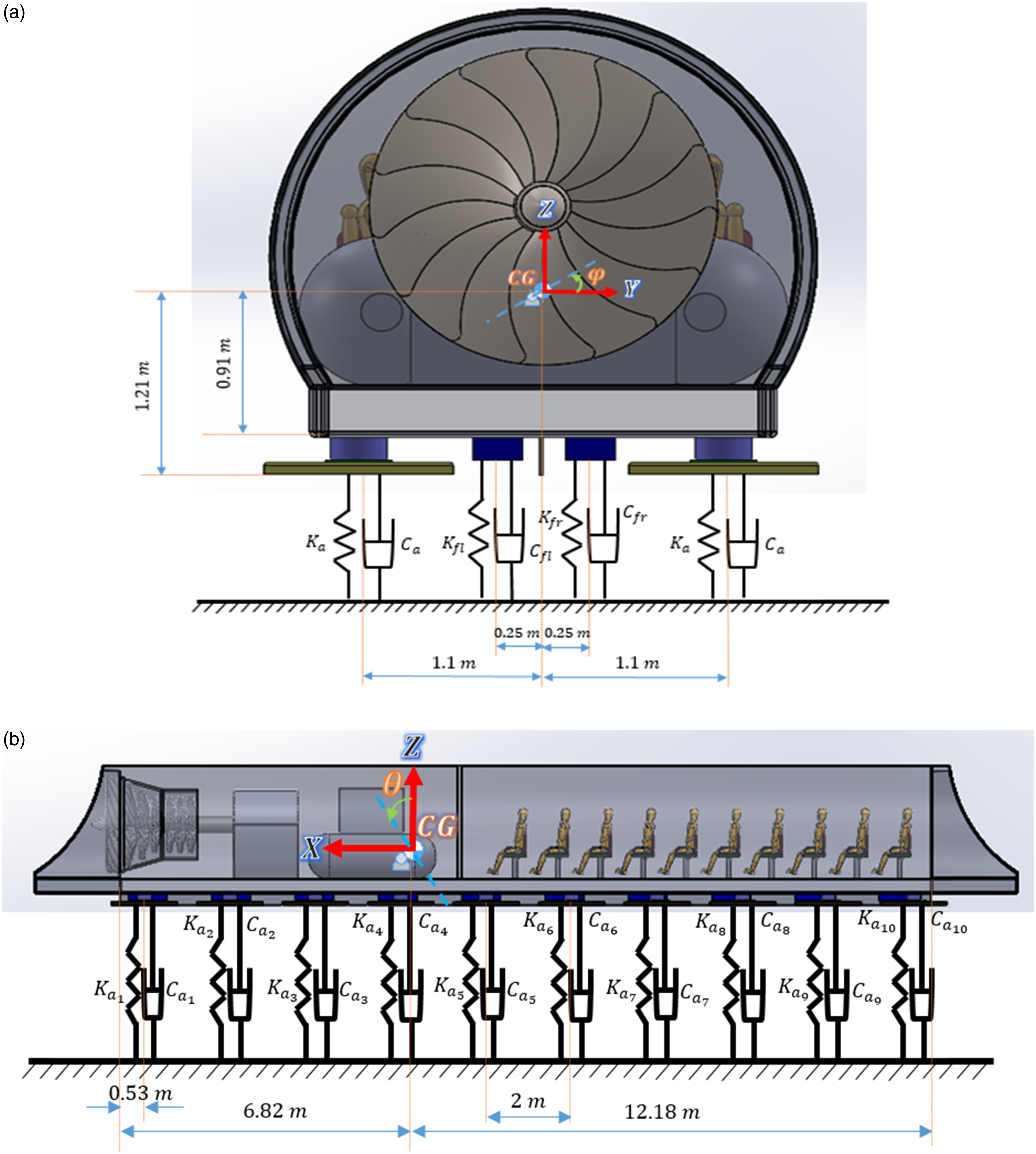
The governing equations of motion
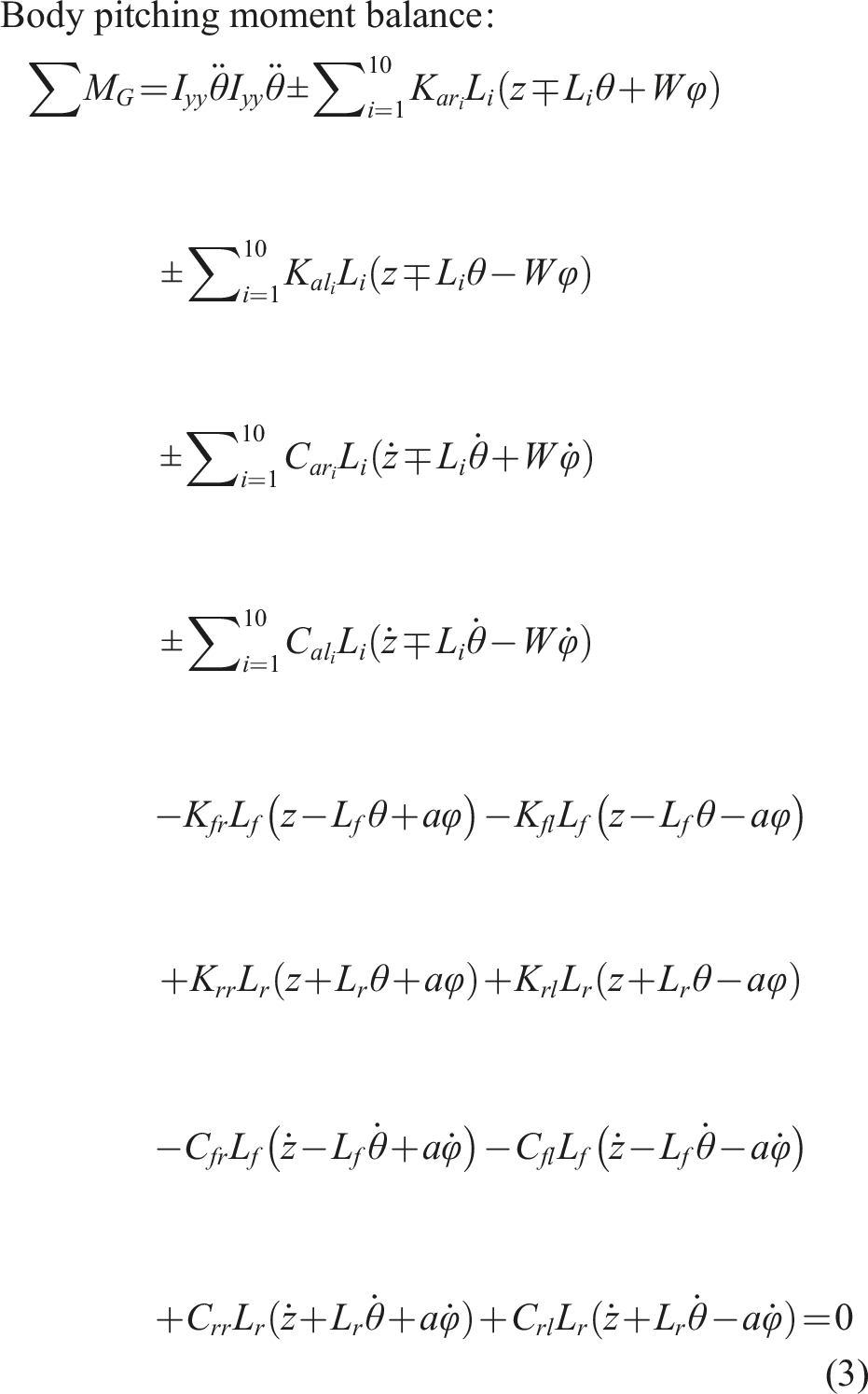
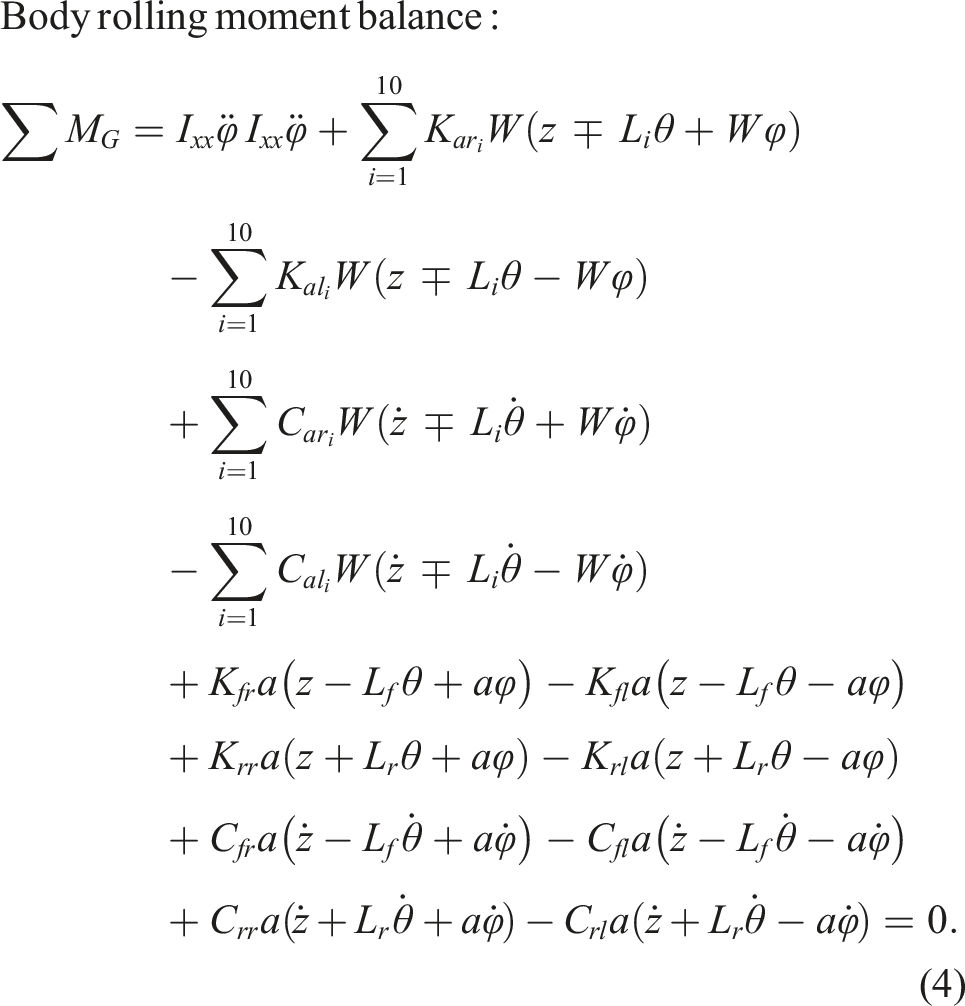
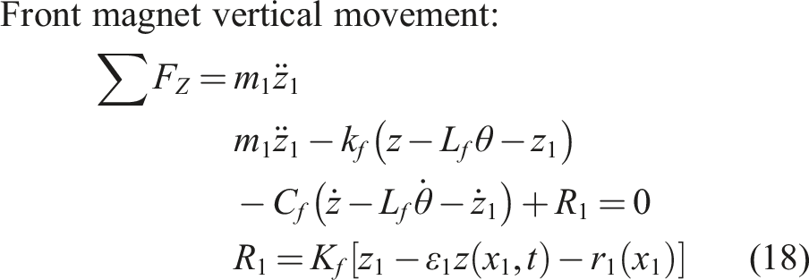
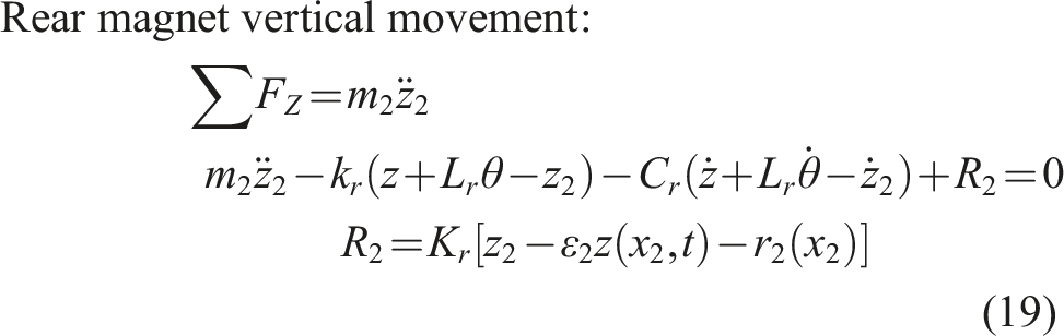
According to the presented dynamic modeling in Figure 4, the governing dynamic equations of the system are derived as follows: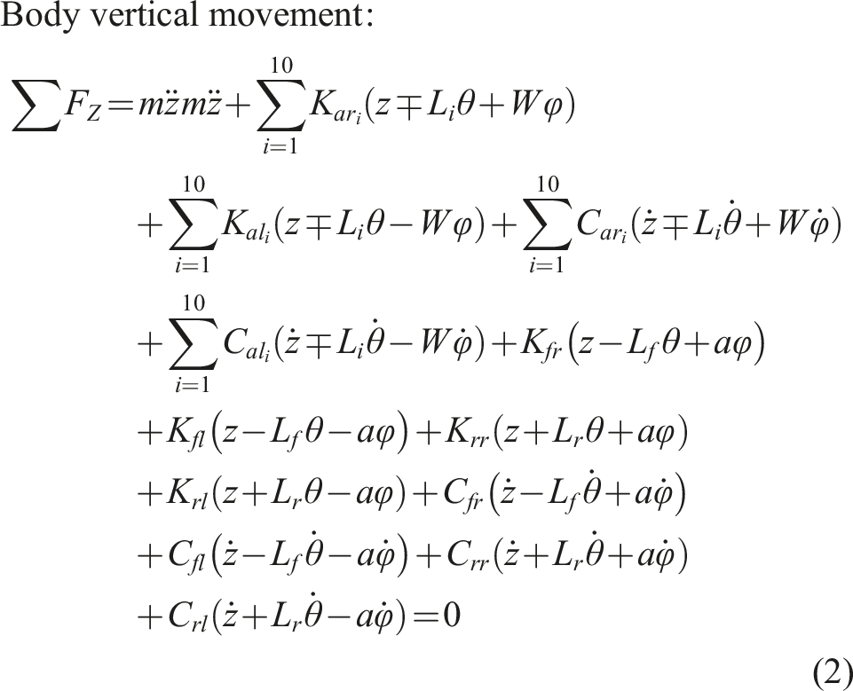
Where
By sorting the sentences in terms of the variables, as well as assuming the equal stiffness and damping coefficients for all the cushions respectively with 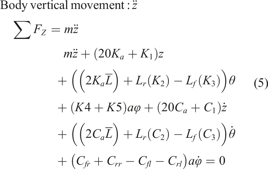
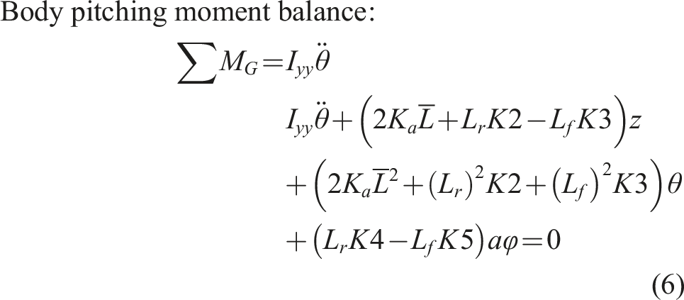
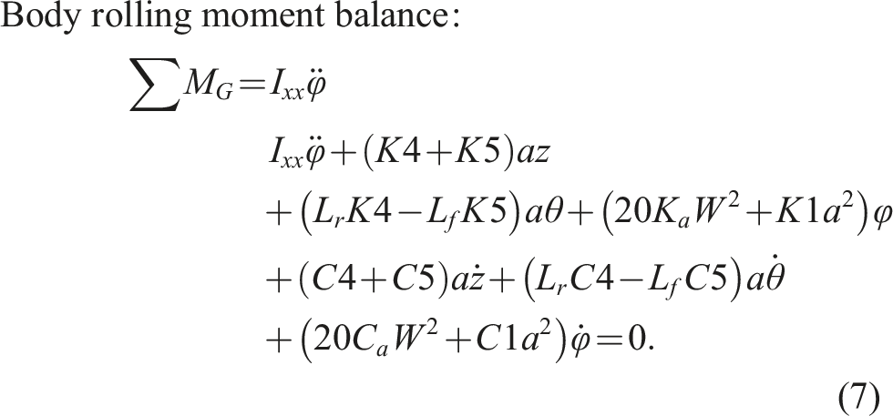
where 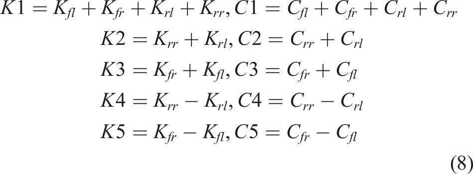
In equations (5)–(7), the governing equations can be described in a matrix form as 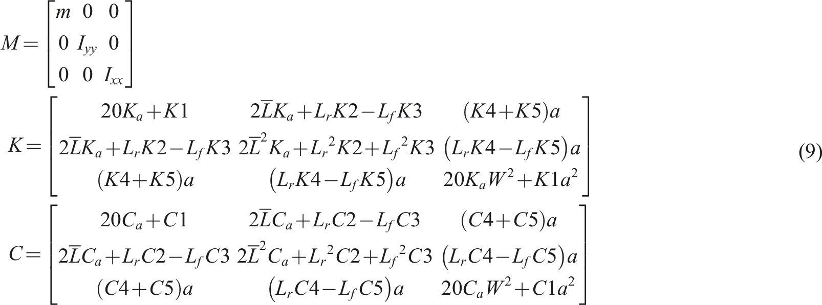
The lift force of every magnet with EDS (inductrack) kind is calculated using the following relation:9,32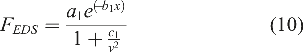
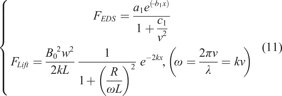
In equation (11), the first relation is taken from Pradhan and Katyayan’s formula,
32
and the second one is from Post and Ryutov’s work.
9
Comparing two relations with each other, the values of the coefficients will be equal to
The equivalent stiffness of every magnet 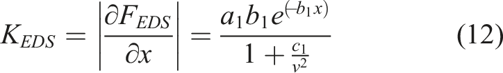
The equivalent circuit of each EDS system is depicted as an RL circuit consisting of a resistance and an inductance with a voltage source. It is necessary to determine the resistance 
where 
where
In the case of air cushions, similarly, the equivalent stiffness of each cushion is calculated by derivative of equation (1) concerning the gap 
Putting the cushion design parameters
Verification
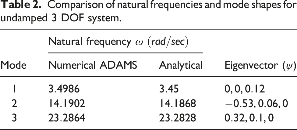
Comparison of natural frequencies and mode shapes for undamped 3 DOF system.
3 DOF vibration modeling of the pod in ADAMS (isometric view).
Comparing the results of computed natural frequencies obtained from the matrix coefficients of the governing equations in equation (9) with MSc ADAMS are reported in Table 2. The results show that the obtained natural frequencies by the analytical method are approximately equal to the MSc ADAMS software. This issue implies the accuracy of the derived equations and the solution method. Also, the eigenvector is obtained to show the pod mode shapes in each vibration mode. In this regard, any variable with a higher numerical value (up to the normalized value of 1) is exposed to more excitation in that mode. The positive sign means that the movement of the variable is in the same direction as the conventional positive direction relative to the origin defined in the system, and the negative sign shows that it is in the opposite direction. Also, the zero value implies that the variable is not excited in that vibration mode. Thus, in the first vibration mode (Mode 1) only the body’s rolling angle is excited, in the second mode (Mode 2) the vertical movement and pitching angle of the body are excited in opposite directions, and in the last mode (Mode 3) the vertical movement and pitching angle of the body are excited in the same directions relative to the defined origin in the system.
In the next section, the effect of acceleration and braking is analyzed on the vibrations of the pod to predict the system’s dynamic behavior in different movement conditions.
The 7-DOF vibration model for predicting accelerating and braking behaviors
In this section, the acceleration and braking of the pod caused by the magnets also are considered. To reach this purpose, longitudinal vibrations in the system are employed, as in the case of Ju and Lin.
18
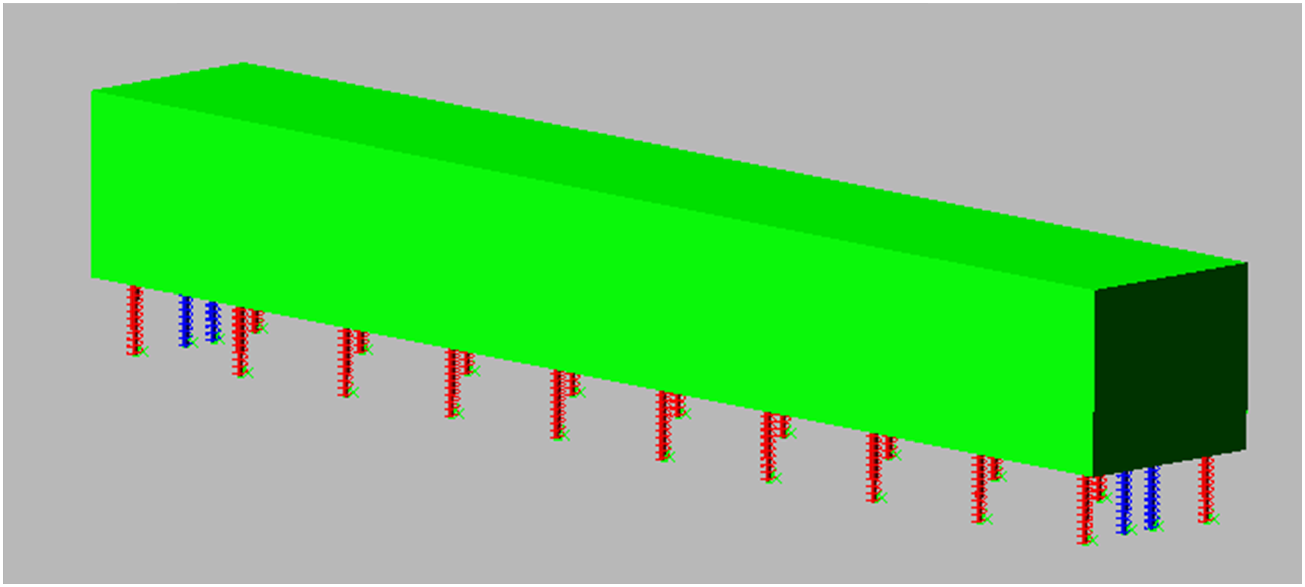
This half-vehicle model is shown in Figure 6 as follows: 7-DOF half-vehicle model considering longitudinal vibrations.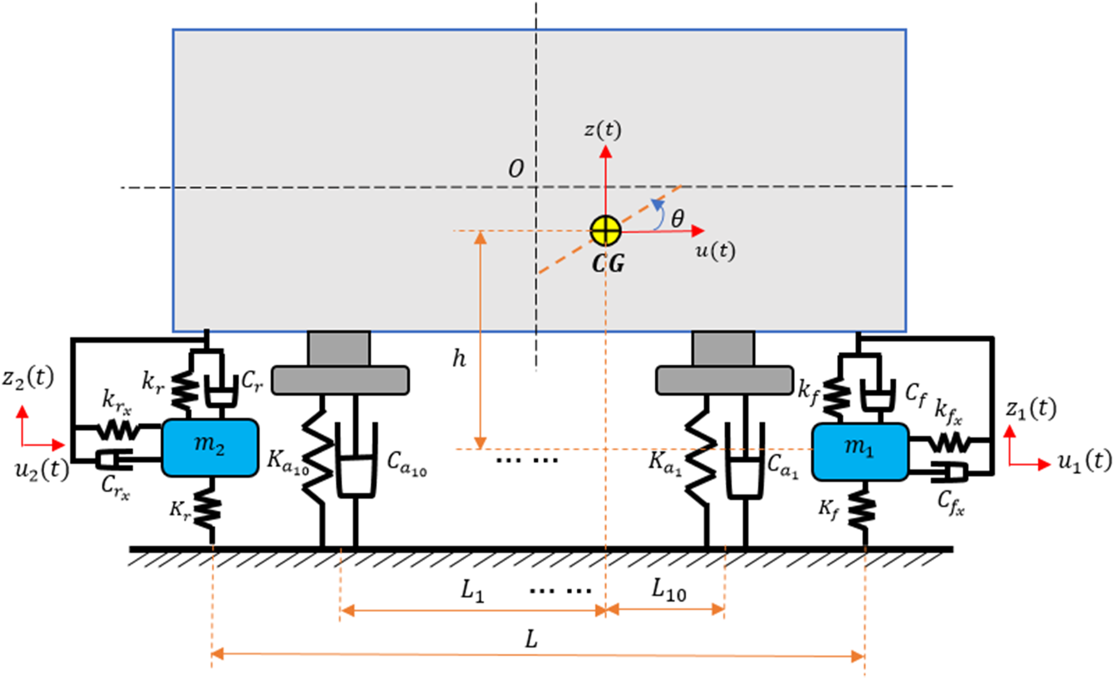
Figure 6 shows the front and rear magnets assuming flexible links relative to the body in vertical and longitudinal directions (4 DOF). The body also has two vertical and longitudinal directions of movement in addition to the pitching moment (3 DOF). Thus, the system overall is a seven DOF model. where 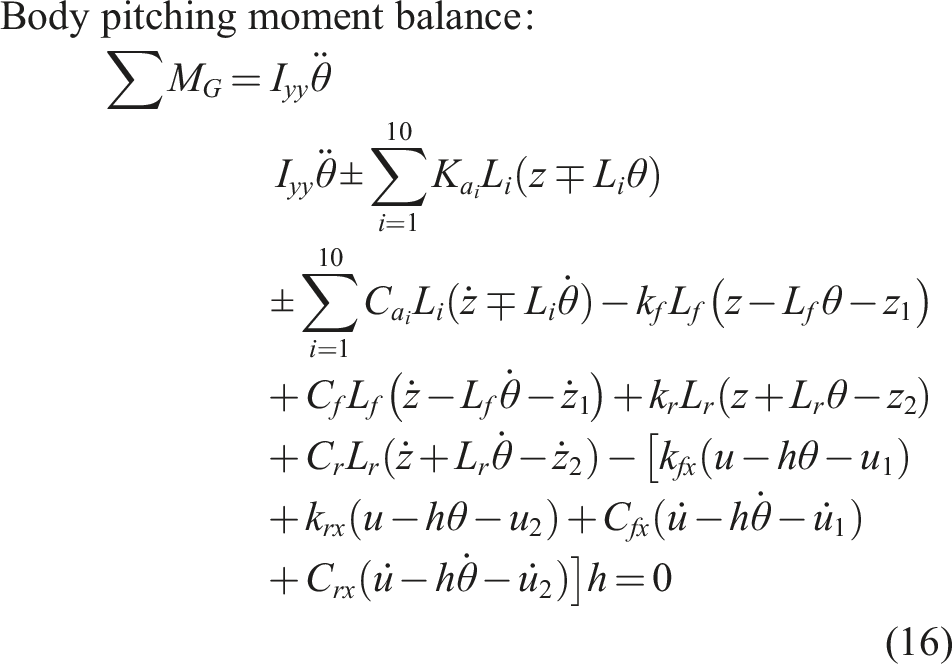
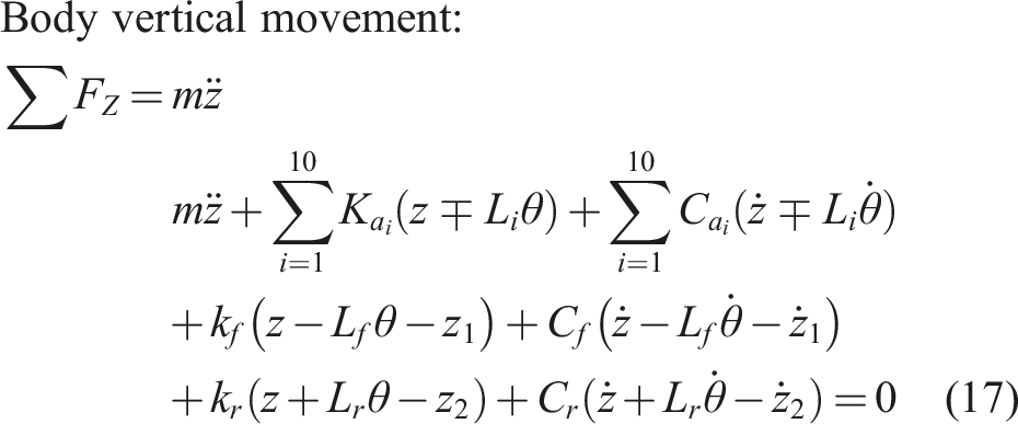
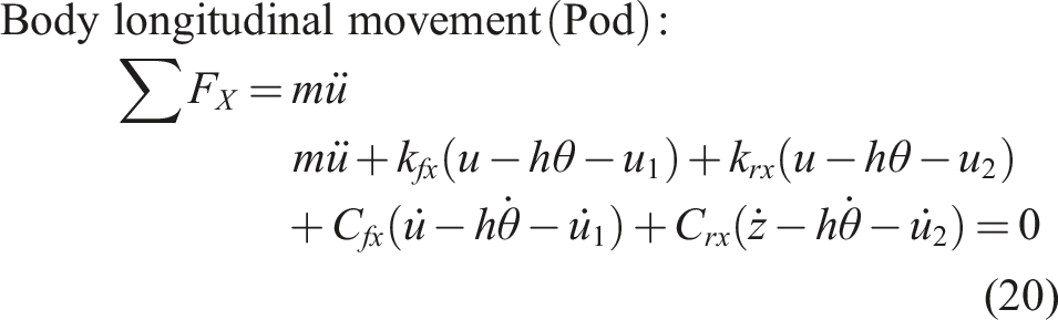
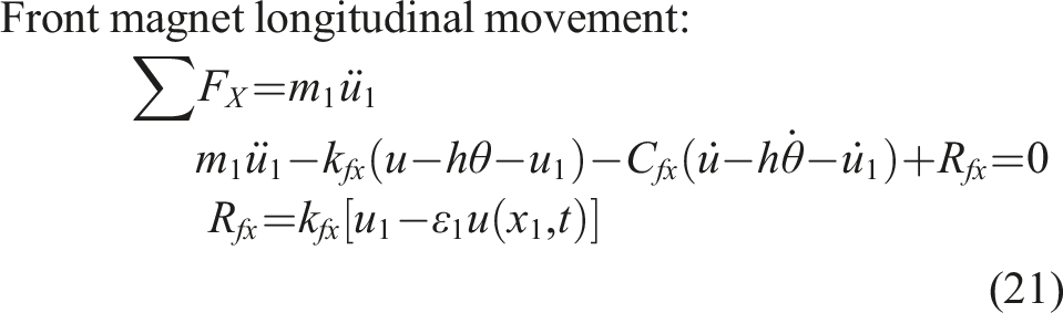
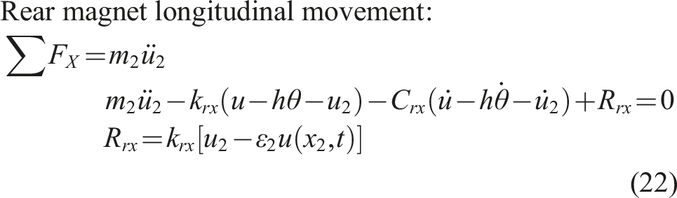
Hence, the governing equations can be written as 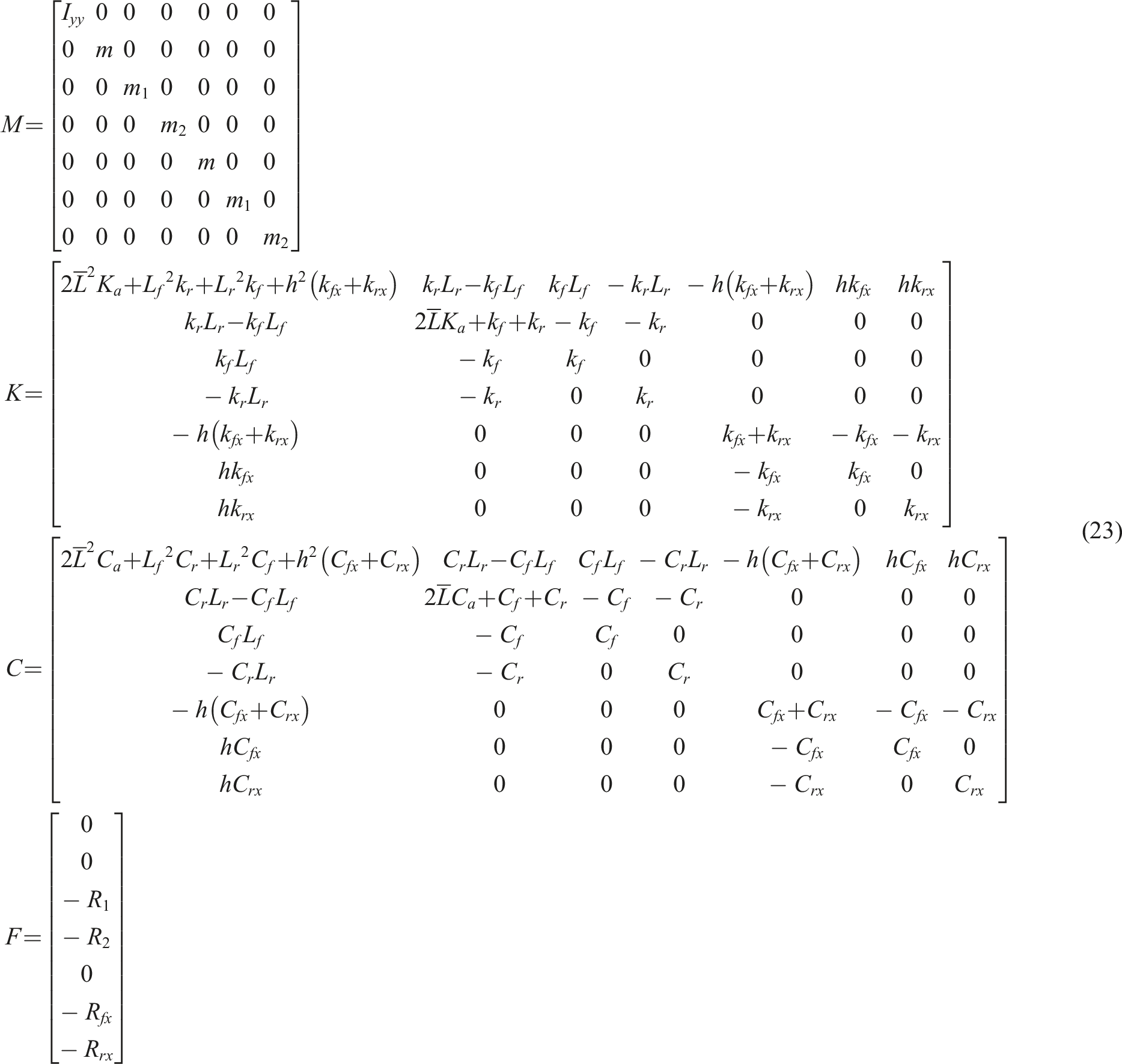
The following relations are utilized between the absolute and relative longitudinal movements for all magnets and the body to consider the acceleration and braking effect: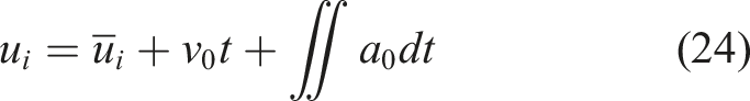
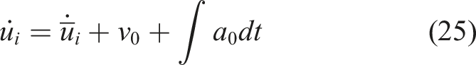

Where
Therefore, Putting equations (24)–(26) in equations (16) and equations (20)–(22), the new equations according to the relative motions can be rewritten as 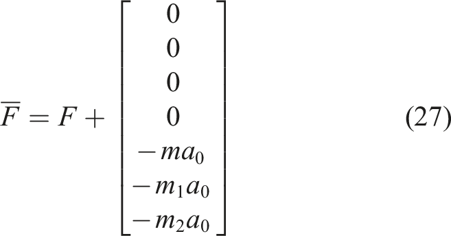
According to equation (27), the inertia force from every mass also is created by considering the acceleration or deceleration. Note that the mass, stiffness, and damping coefficients matrix will not change, and they are the same as equation (23). Also, if the longitudinal vibrations of the system, as well as the existence of the air cushions, are neglected, then the system is converted to a four DOF vibration model like the dynamic model proposed by Pradhan and Katyayan 32 for their designed pod called “OrcaPod”.
Numerical results and discussions
In this section, numerically, the 7-DOF derived equations are solved considering the acceleration and braking effects using MATLAB. In this study, the track irregularity and displacements effects are neglected. Hence, to solve the problem conveniently, variables should be reduced from the second order to the first order. Therefore, in equations (16)–(22) the acceleration of each variable is calculated in terms of other variables’ displacements and velocities in every simulation step time. In this regard, each of them is defined as an input variable in the state space equations. Therefore, the input variables can be defined as the new 14 variables
The dynamic equations are solved numerically using MATLAB Simulink. The numerical data of the proposed model of the pod are
Assuming the zero initial value for the variables relative to the stable points, equations (16)–(22) also can be solved numerically. In this regard, three separate scenarios are developed for the system to consider the various behaviors of accelerating and braking maneuvers. The first scenario is moving the pod at a cruise speed or The body (a) pitching angle, (b) vertical, and (c) longitudinal vibrations versus simulation time. The front and rear magnets (a) vertical and (b) longitudinal vibrations versus simulation time.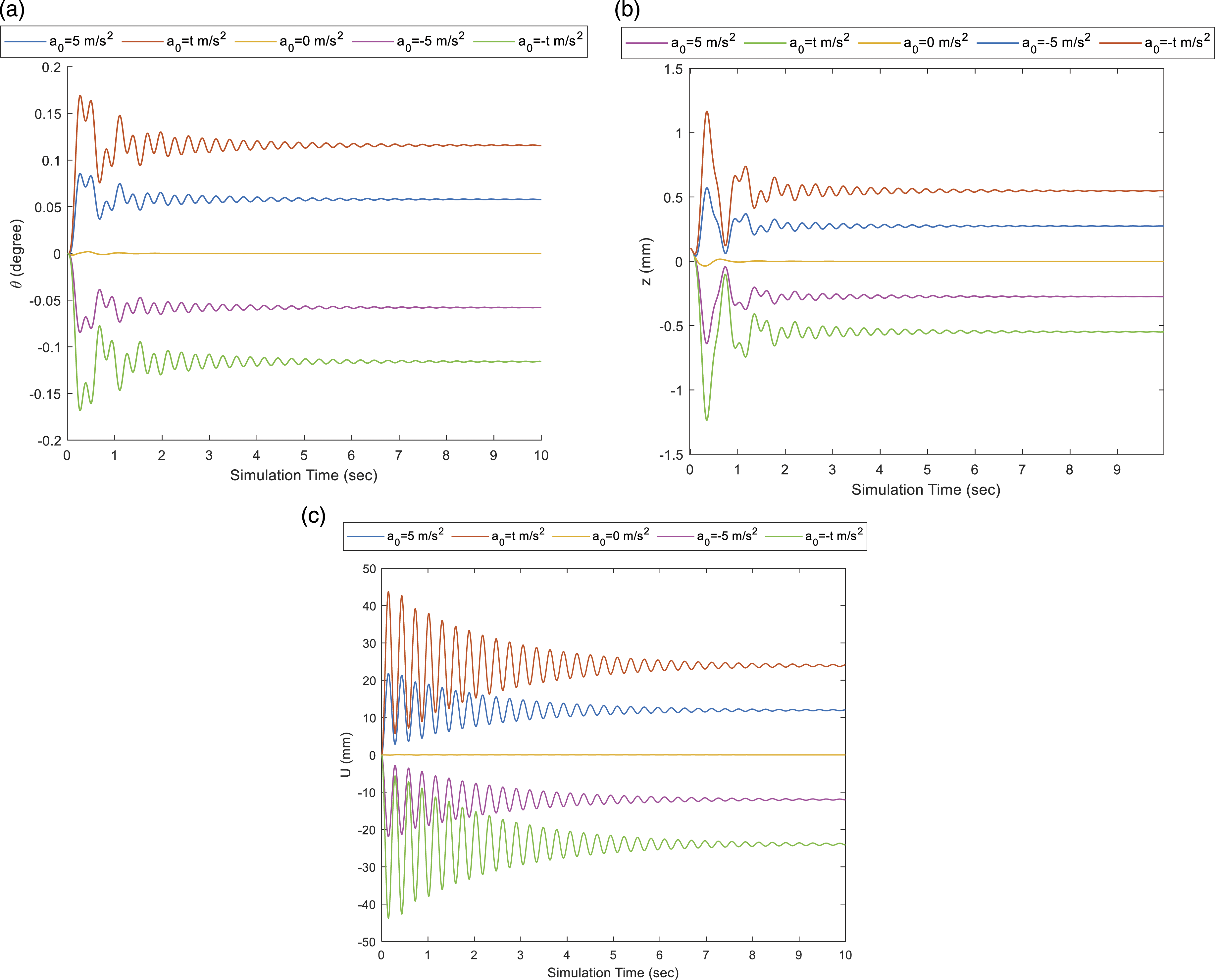
In Figure 7, the body’s longitudinal and vertical movements and the pitching angle are plotted during the time in different cases.
According to the results obtained by comparing the three scenarios, including the cruise speed (
Also, comparing the other scenarios in the equal condition during 10 s of simulation time (average acceleration/deceleration of the linear time-variant state also becomes
The pitching angle and vertical movement increase due to generated external forces (
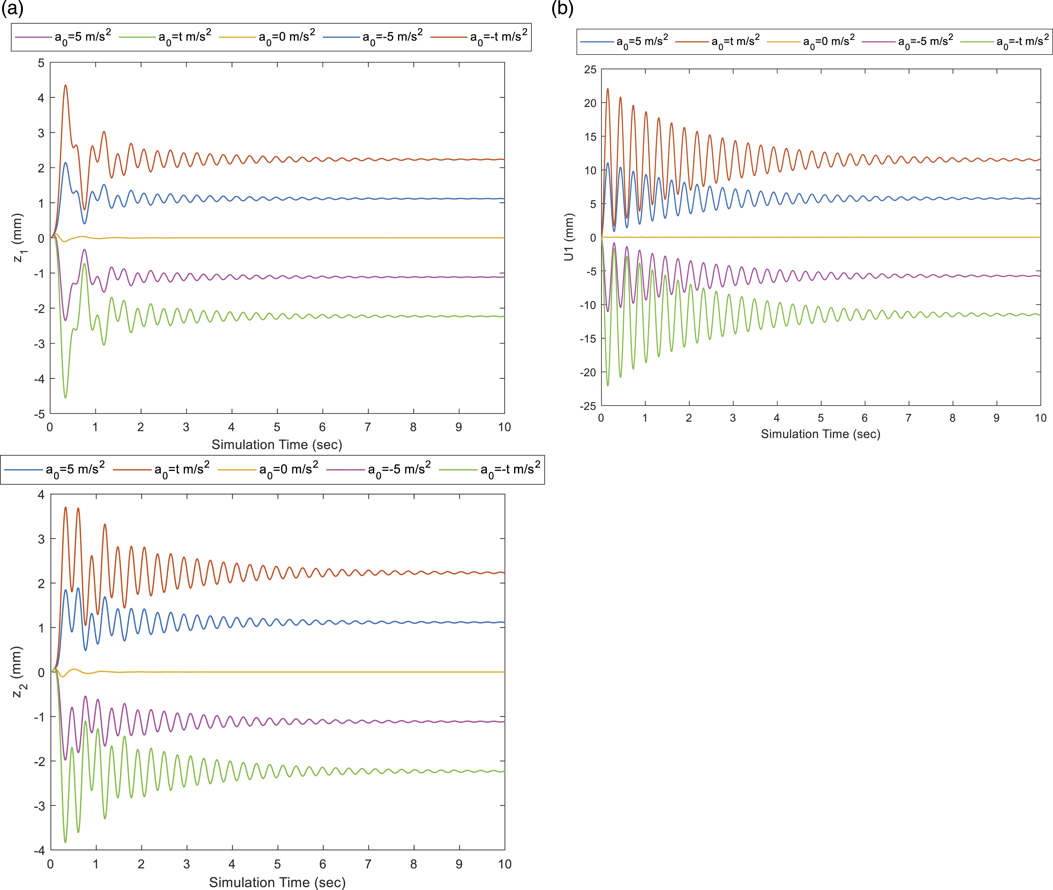
In Figure 8, the longitudinal and vertical movements of the rear and front magnets are depicted during the time simulation in different cases. In these diagrams, again, the variable acceleration/braking creates the highest oscillations compared to the others. In the vertical movements, the front and rear magnets oscillate suddenly in the first 2 s of simulation time, so they reach their maximum range of fluctuations almost in the first second, like the diagrams of the body’s vertical movement and pitching angle. But the oscillations form of front magnets differs from the rear ones. However, their longitudinal displacements are similar in behavior. Therefore, one of them is analyzed. Similar to the longitudinal displacements of the body, for the longitudinal movements of the magnets, the expiration of variable acceleration/braking fluctuations is later than in the constant acceleration case.
Conclusions
This paper proposed a new conceptual industrial (large-size) pod containing electrodynamic and air cushion levitations. In this paper, performing CFD simulations using Ansys Fluent software, a nonlinear dynamic model of the air cushion was provided, and a 3-DOF dynamic model was assumed for the proposed pod verified by using MSc ADAMS software. The model was developed into a 7-DOF to predict the vibration behavior of the pod in accelerating and braking maneuvers. The governing dynamic equations were derived and solved using MATLAB. Finally, the paper proposed three separate scenarios for accelerating/decelerating by investigating the vibration behavior of the pod in different accelerating and braking maneuvers conditions, presenting simulation results: constant speed, constant acceleration, and linear time-variant acceleration. Results showed that the minimum vibration of the pod is corresponded to the constant speed scenario with zero value. Then, comparing the other ones in the equal condition, the constant acceleration/braking provides fewer vibrations for the pod than the linear time-variant acceleration/deceleration. Thus, the pod movement with average acceleration/braking is more appropriate than the variable acceleration/braking state.
Footnotes
Declaration of conflicting interests
The author(s) declared no potential conflicts of interest with respect to the research, authorship, and/or publication of this article.
Funding
The author(s) received no financial support for the research, authorship, and/or publication of this article.