
Abstract
This paper proposes a new approach to the dynamic modelling of railway track switches. The approach results in a model which faithfully reproduces the dynamic bending of the switch blades, allows simulated actuators (forces) to be applied along the length of the rails and can be simulated in times that are an order of magnitude faster than similar models in multi-body dynamics software (such as Simpack). These are the main contributions that should be of use to researchers and engineers concerned with the design of switches and their actuation mechanisms. First, an actuator model is developed; then the switch blade FEA (Finite Element Analysis) model is developed and validated against static bending predictions; the two are then combined and validated against the dynamic and steady-state predictions from a validated Simpack model. The complete model can be found here: https://doi.org/10.25500/edata.bham.00000884.
Introduction
Track switches are electric or hydraulic mechanical systems installed on the track, which allow railway vehicles to switch from one route to another, thereby providing flexibility for the railway network.
1
There are types of various railway switches in operation in the UK. The most common of these are Clamplock, HPSS, HW, and mechanical point machines.2,3 Figure 1 gives an equivalent track switch model. Equivalent model of a track switch system.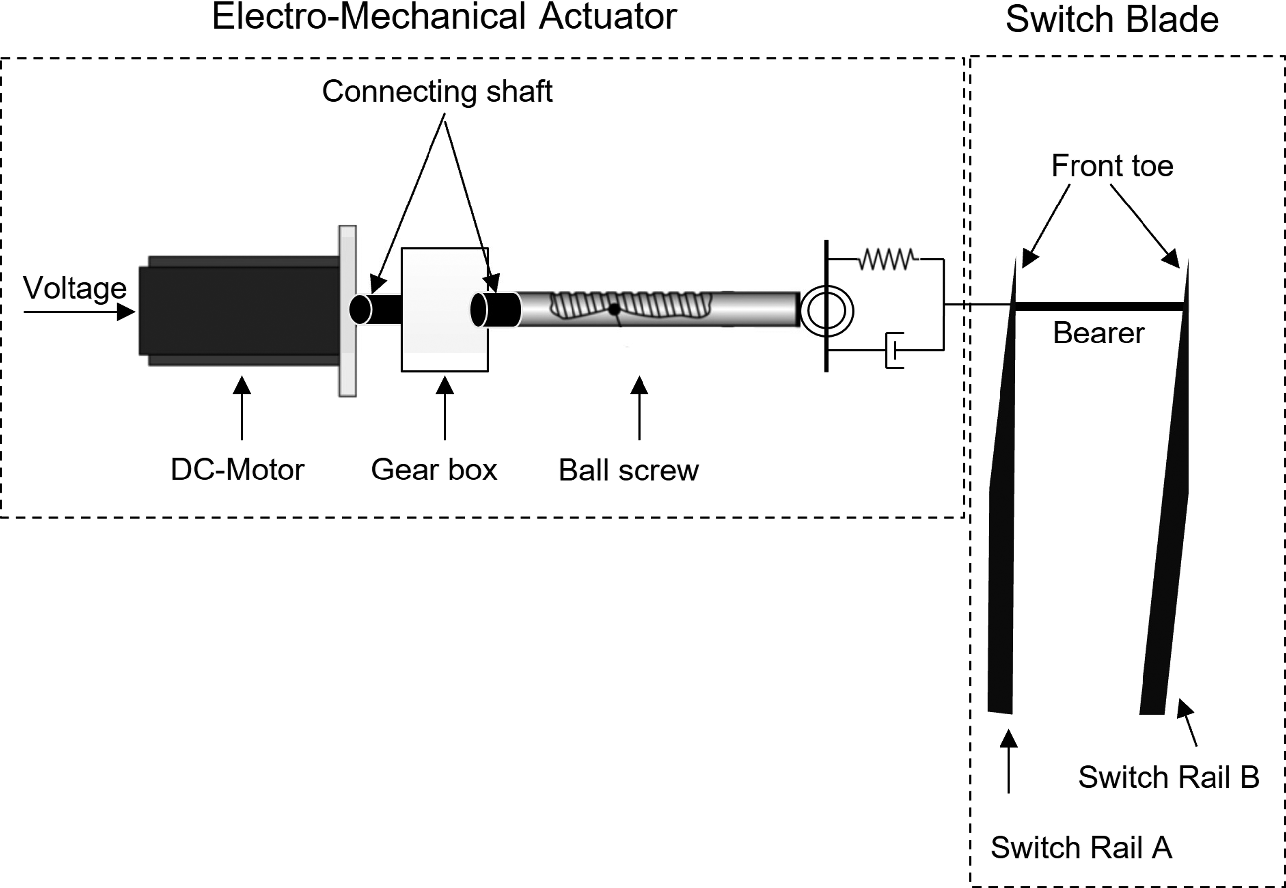
At present, there are a large number of mechanical modelling and design software for structural optimization or dynamic evaluation, such as Simpack in Germany, NUCARS of the North American Railway Association, MSD.ADAMS/Rail, and general mechanical modelling software, such as Abaqus, ANASYS, etc. 4 In the structural design and bending analysis of the switch, the finite element analysis method is widely used. To study the interaction between train and track, Andersson and Dahlberg modelled the turnout through linear finite elements with modal damping5,6. Bruni et al. built a detailed three-dimensional finite element model in ABAQUS to study the vehicle’s dynamic behaviour when running over turnouts. 7
Recently, researchers have shown increasing interest in improving the performance, safety, and reliability of the railway network from projects such as S-CODE, 8 In2Rail, 9 and REPOINT. 1 A Repoint switch prototype simulation model is established using McCauley’s method in MATLAB/Simulink. 10 The researchers also developed a track switch model using the multi-body simulator Simpack, bending the switch track to a single actuator of a REPOINT-light switch, 11 and then a full-scale demonstrator for the novel railway track switch was built. 12 Besides, to research and design a new approach to railway track switch actuation, Dutta et al. first modelled a rail unit by finite element analysis (FEA) in ABAQUS, then generated a complete switch system through Simpack, and finally linked it into Simulink to form a co-simulation space. 13 However, this kind of simulation in the co-simulation environment requires an extremely long computational time, approximately several hours to simulate one second. Therefore, it is helpful to utilize a more effective method for research work within a limited time range.
Compared to past work, the key innovation in this paper comes from applying finite element modelling methods, to represent the switch blades, directly in MATLAB/Simulink. This simplifies the model somewhat, removes the need for co-simulation of the track, actuator and control system and results in a single system model. The first benefit is that this significantly reduces the time required to run the model and obtain overall system simulation results. Secondly, independent actuation forces (from separate actuators) can be applied at different locations along the length of the switch blades model. At the same time, the system-level simulation is able to reproduce the behaviour predicted by the more complex (and significantly slower) co-simulation approach.
The paper is organised as follows. In the (next) modelling section, the actuator model is developed; then, the switch blade static and dynamic FEA model equations are presented. Subsequently, in the simulation results section, the dynamic model is compared with the static bending predictions and the dynamic predictions from a previously published model in Simpack. In the final part of the results section, the actuator and blade (bending) model are combined and validated against the dynamic and steady-state predictions from a validated Simpack model; and a set of static experimental results. The final part of the paper draws conclusions from the work and suggests future directions and uses for the new system-level switch model.
System modelling
The full switch model is obtained through a physical analysis of its components. The aim is to provide an easily accessible and transparent description of the physical behaviour of the switch. Although different switches in the installation have different parameters, the models and interactions of the sub-components remain the same. In this paper, the switch layout is based on a typical CVS-type switch,
3
and actuation and locking are provided by a High Performance Switch System (HPSS) type machine, with a non-back-drive-able lead screw. The complete switch system is mainly composed of two parts, namely the actuator and the switch blade. The actuator receives power from the line-side cabinet and drives the front toe to move the switch blade from one position to another. Figure 1 gives the structure of the entire track switch system with five main components: the motor model, the gearbox model, the mechanical linkage model, the ball screw model, and the switch blade model. Each of these components is discussed below where a simulation model is shown in Figure 2. Simulation model of the track switch system.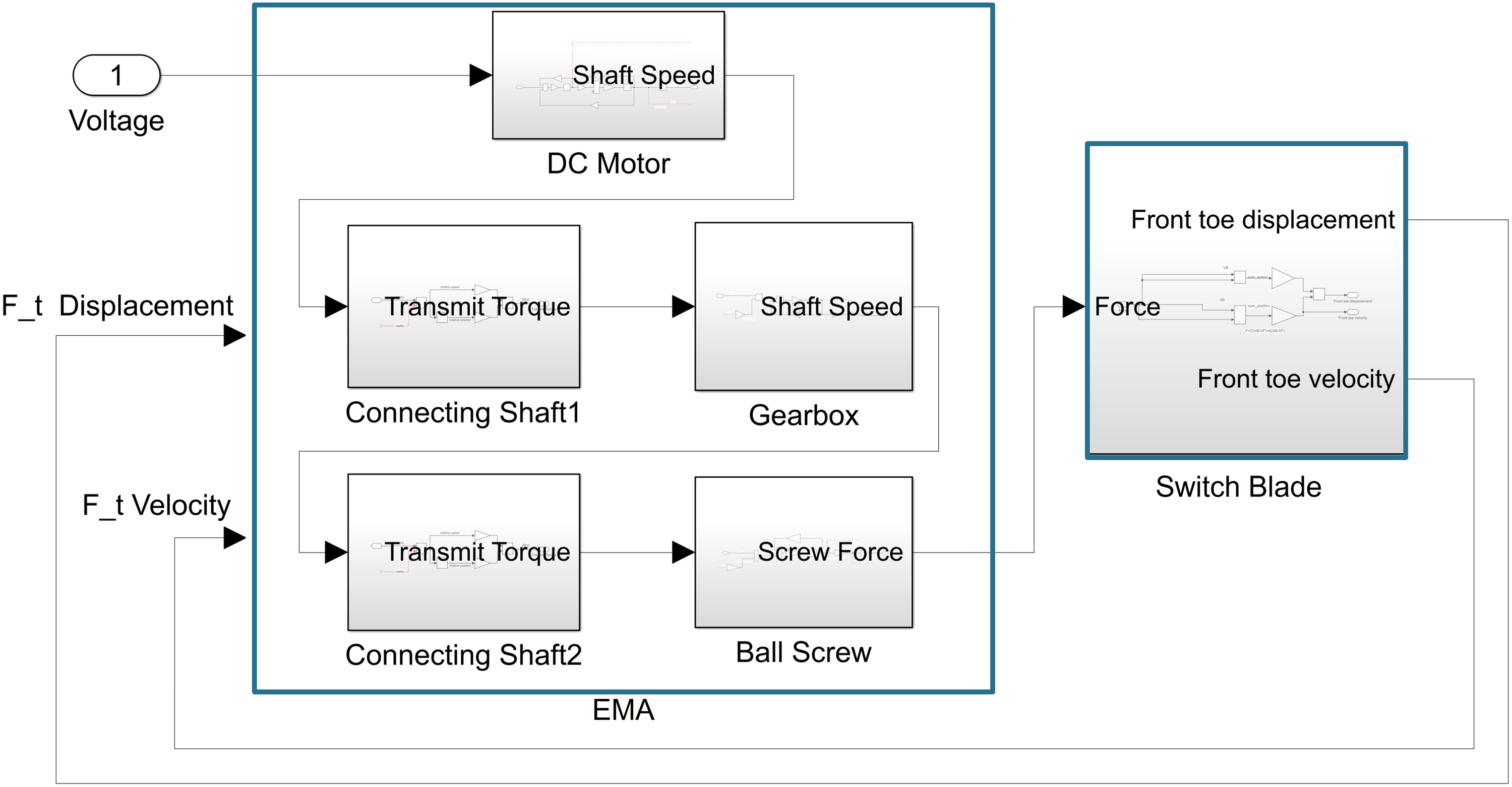
Electro-Mechanical actuator model
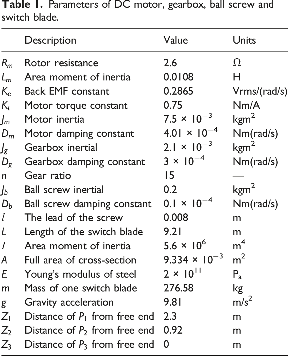
Parameters of DC motor, gearbox, ball screw and switch blade.
The motor input voltage, V drives the motor to cause the motor shaft to rotate at the motor speed of 

The mechanical equation for the motor is derived using Newton’s second law of motion, thus, a linear model can be obtained using the torque balancing rule:
The gearbox is a reduction mechanism that reduces the angular velocity and amplifies the motor’s output torque, which is linked with the motor by a connecting shaft.
The transmitted shaft torque equation is described as:
The gearbox mathematical equation is written as: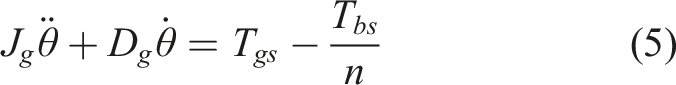
The ball screw converts the rotational motion of the connecting shaft into linear motion. 
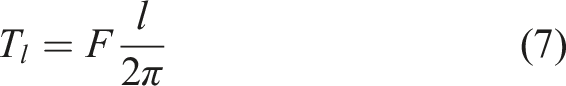
Assuming that the ball screw and the switch blade are rigidly connected, they can be modelled as a stiff spring-damper assembly. The actuation force can be calculated by the linear motion of the ball screw and the switch blade,
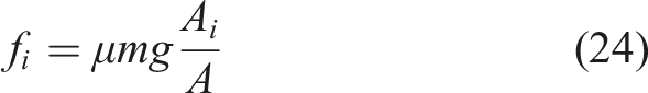
The contact force between the switch rail and the stock rail is modelled by an extremely stiff spring and damper which is switching on when the switch blade makes physical contact with the stock rail, the purpose of which is to restrict motion. The contact force 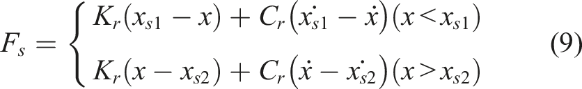
Switch blade model
Two methods are adopted for switch blade modelling in this paper. One is considering the switch blade as a beam to analyse the deflection properties. The second is to use the finite element analysis method to establish a dynamic model in Simulink. 14 The static bending analysis can be regarded as a reference for the dynamic model.
Static rail model
When the switch blade is in motion, it is driven by a lateral load. Only one bending mode of the horizontal (x-z axis) is considered. The bending switch blade is considered as a cantilever beam under the action of the three ideal forces to describe the deflection properties.
14
A shear diagram for the switch blade is shown in Figure 3. Three forces Schematic for horizontal deflection of the switch blade.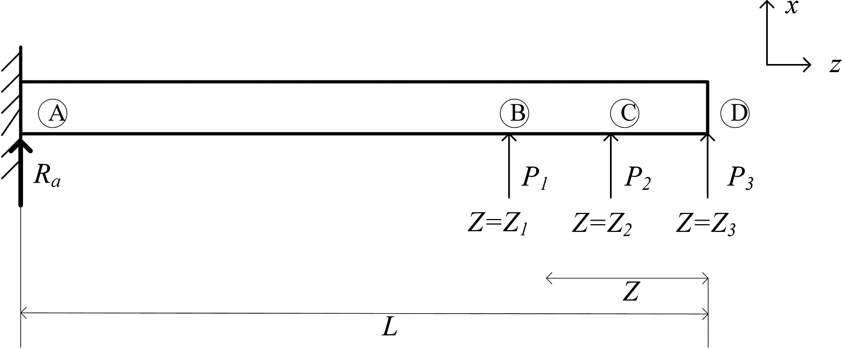
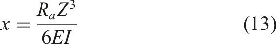
The deflection equation for the switch blade is calculated by the integral of the bending moment equation. The deflection of the switch blade is different in the AB, AC, and AD sections. The reaction force is calculated as 

Section A to B:
Section B to C:
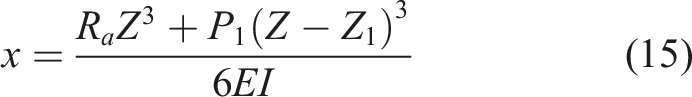
Section C to D:
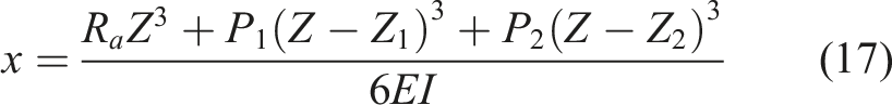
The parameters used for the analytical bending equations (10), (11), (12), (13), (14), (15), (16) and (17) are derived from the switch rail presented in Table 1.
Dynamic rail model
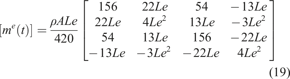
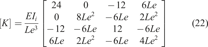
The dynamic model adopts a finite element method. In the classical finite element method for analyzing the beam bending problem, the 2-node Hermite element is usually used. 15 Suppose the switch blade consists of 2 elements.
The stiffness and mass of each element is obtained as,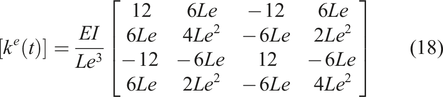
Due to the characteristics of the switch blade, the cross-sectional area and moment of inertia vary with the position. Starting from the front of the front toe, the cross-sectional area of the tip gradually widens. The cross-section is full until the distance at point Z, 5.037 m away from the front toe.
13
A 3D view of a switch blade model shows the change in cross-section, displayed in Figure 4. A 3D view of a switch blade model.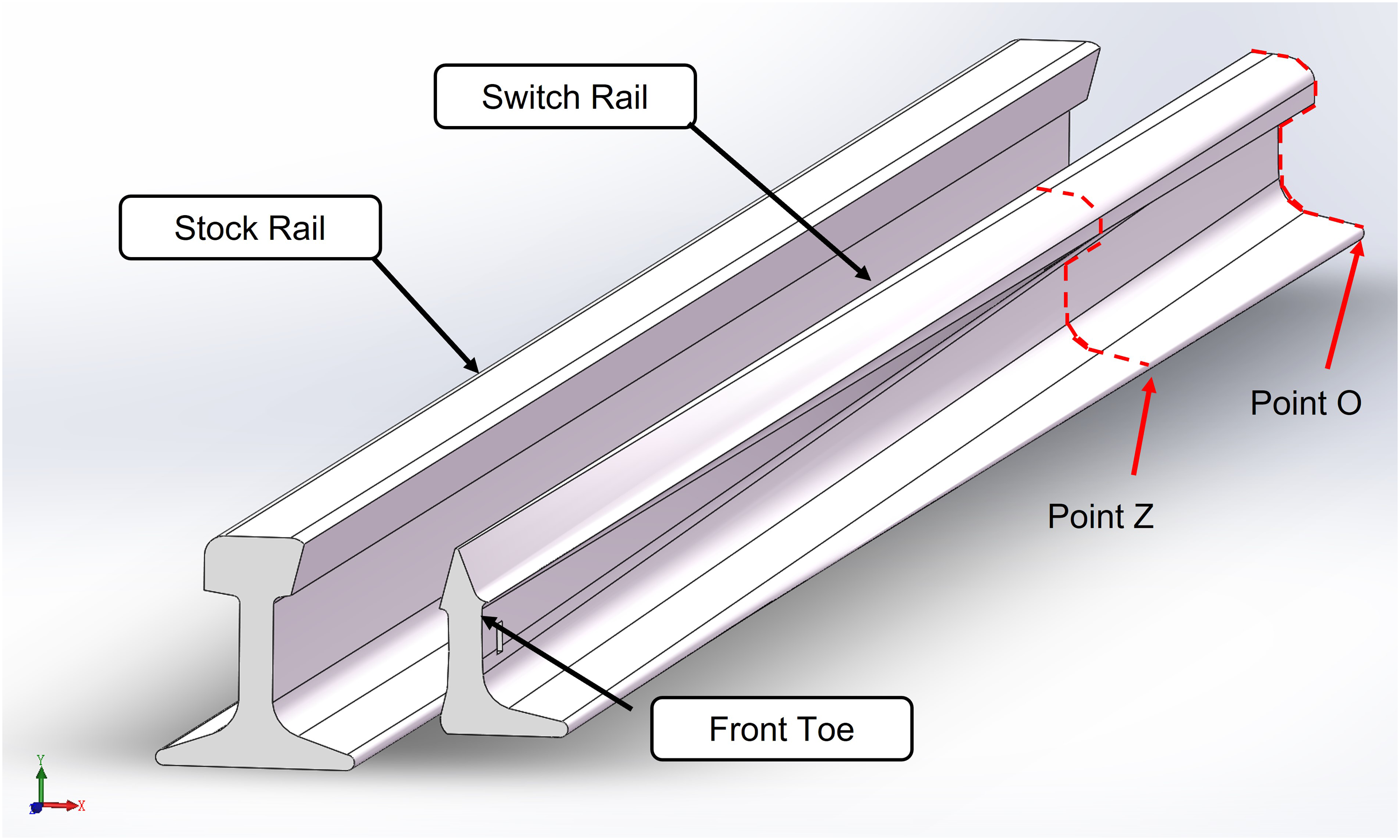
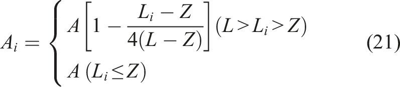
The area 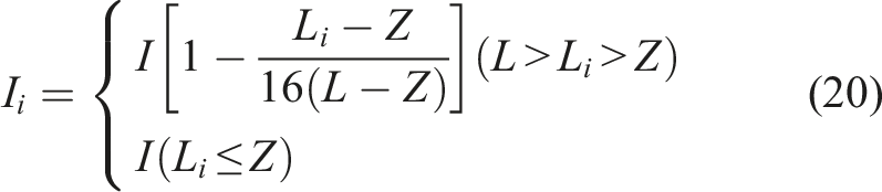
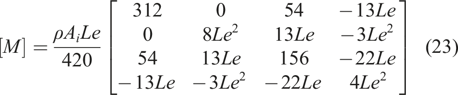
For dynamic simulation, the damping is considered as proportional Rayleigh damping16,17 and the full dynamic system equations are written below. 

Next, a pair of switch blades is built, and the schematic diagram is displayed in Figure 5. The switch rail A and the switch rail B are both composed of 20 elements. The red nodes are the joints. The illustration in the circle shows the principles of the two red nodes’ connection. A schematic diagram of two switch blades.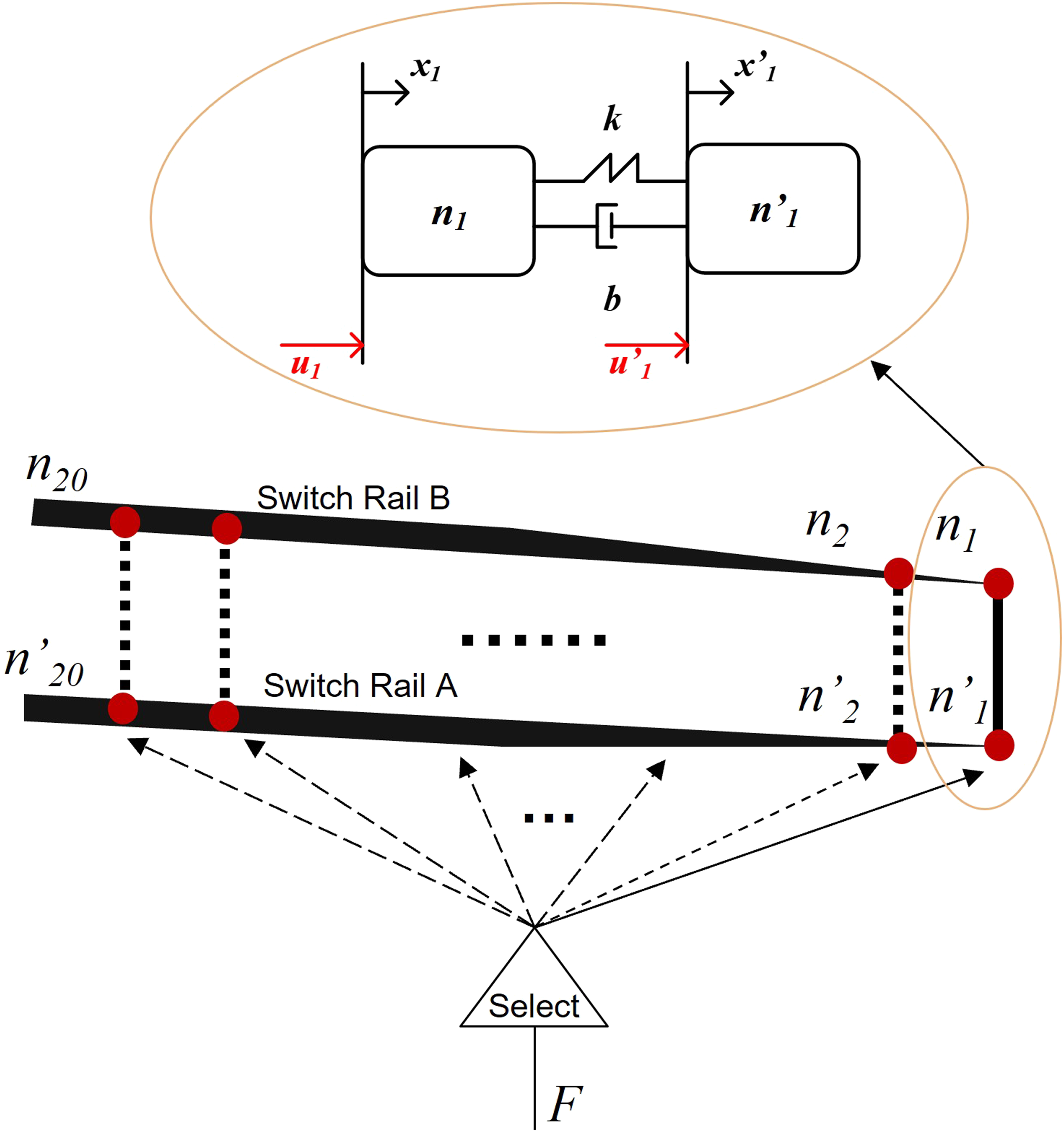
According to Newton’s second law, the force balance equation for 

A select function is made in Simulink to choose which red node or nodes should be rigidly connected. On this basis, each node acts as an excitation point to control its degree of freedom. External forces from the actuator can be applied at any node or nodes to observe the deformation state of the switch blades.
Simulation results
A full track switch system simulation model is established in MATLAB/Simulink, including an actuator model and a switch blade model. Two parts of the results are discussed: switch blade bending analysis under full-scale parameters and simulation results when the electro-mechanical actuator is connected to the switch blades.
Switch blade model results
Based on the previously discussed static bending analysis, the established finite element dynamics model can be verified. Note that there are three positions on the switch blade to bear the load of three points ( (i) discuss the results when applying an external force only at the position (ii) compare the analytical results with the FE steady-state dynamic response in seven different situations; (iii) validate the forces against results obtained from Simpack.
Single applied force
A single point load increasing in steps of 100N from 0N to 1000N acts on the rail at Rail bending when subjected to the different forces.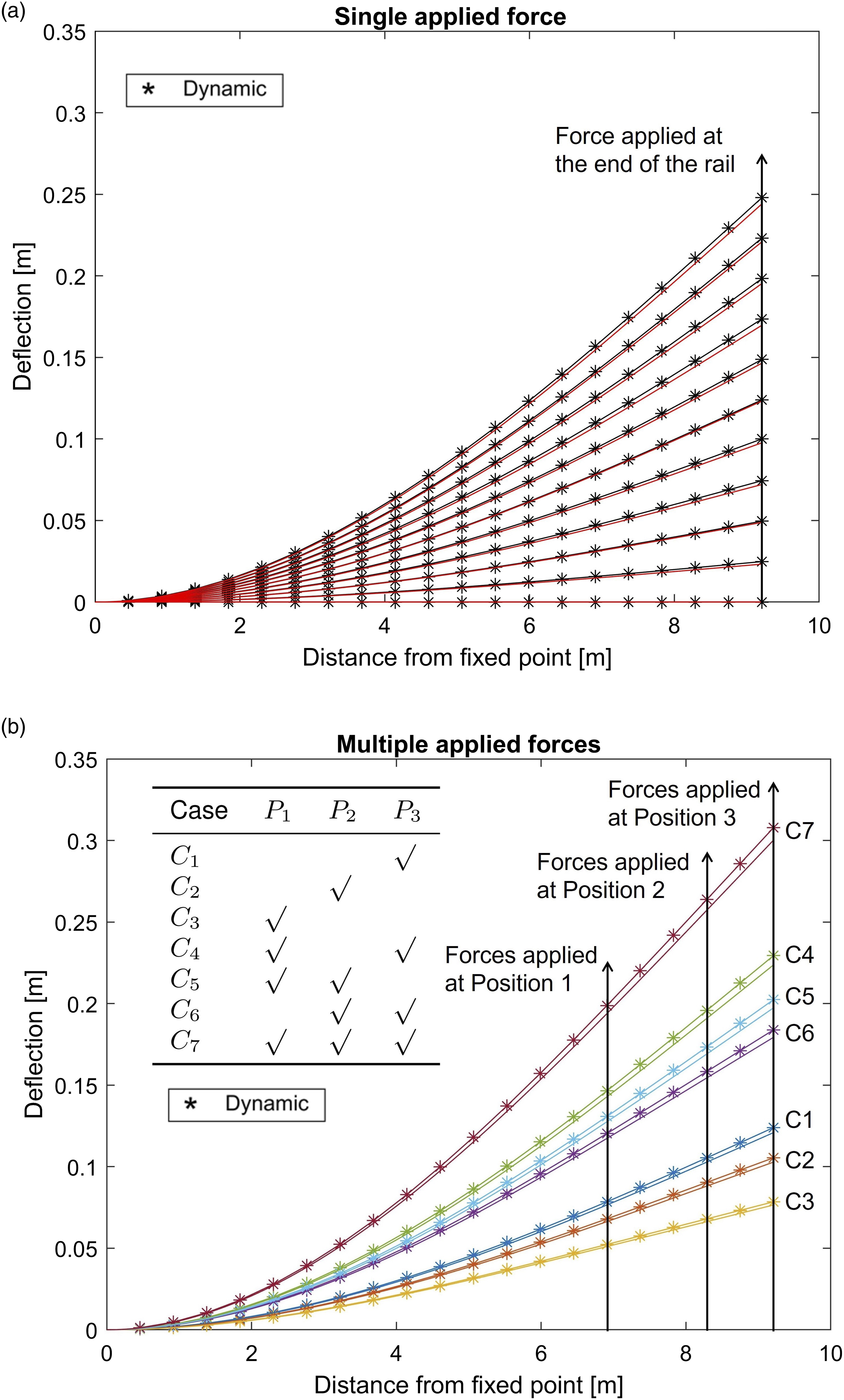
Multiple applied forces
Here different combinations of forces are applied along the length of the rail to observe the influence of multiple external forces on the switch blade. Three equal forces of 500N are applied to the three indicated positions
In the steady-state, there is a small difference between the static results and the dynamic deflection of each element along the track length, caused by the difference in the number of elements. The dynamic and static deflection is closest at the points where the individual forces
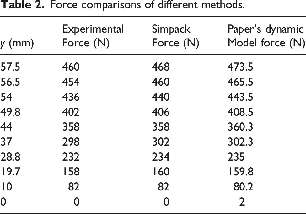
Validation against Simpack and experimental results
Force comparisons of different methods.
Combined blade and actuator model results
In this section, a complete switch model is compiled using MATLAB/Simulink, as shown previously in Figure 2. The input of the actuator model is voltage, and the output is the actuator force. The force is applied to the front toe position. This combined model is validated with the HPSS model built-in co-simulation of Simpack/Simulink and the data details can be found in the reference [13]. The available data is the displacement of the front toe and the current of the DC motor, as displayed in Figure 7. The same command input step of a constant voltage of 120 V is applied to the Simulink model to cause a movement at time 1 s. Once the switch blade closes the gap at the corresponding stock rail, the motor current will rise and the motor will be switched off. The results show that at around 3.7 s, the front toe displacement can reach 0.1 m, which matches the required switch blade travel. The slight differences in the current figure between the Simpack and Simulink models are due to the inclusion of some other mechanical connections in the original complicated Simpack model. Overall, the comparison between the simulation results and the available data shows that the model has a good fit. It can be concluded that the model is a good representation of the full switch system. Model validation for the front toe displacement and the DC motor current.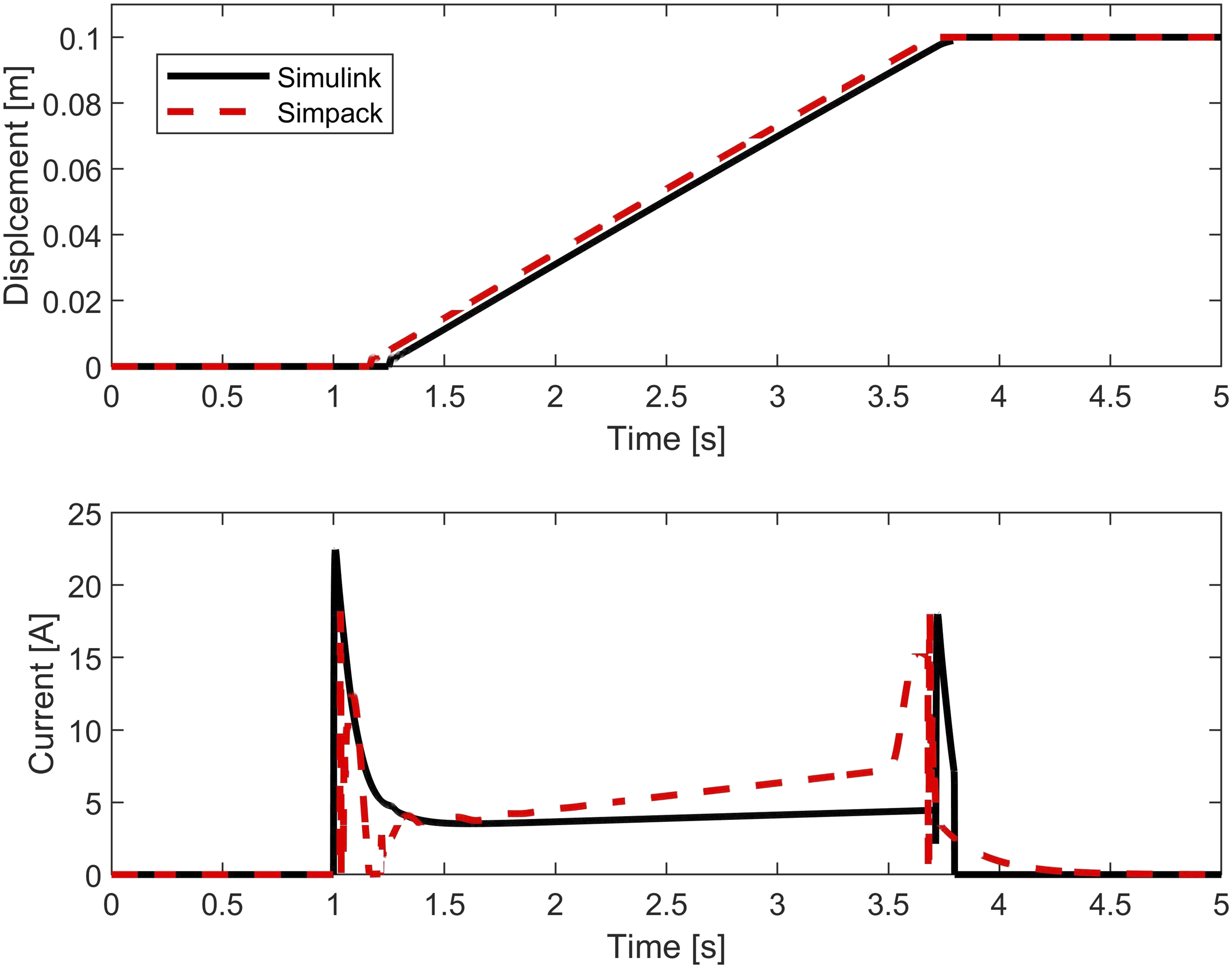
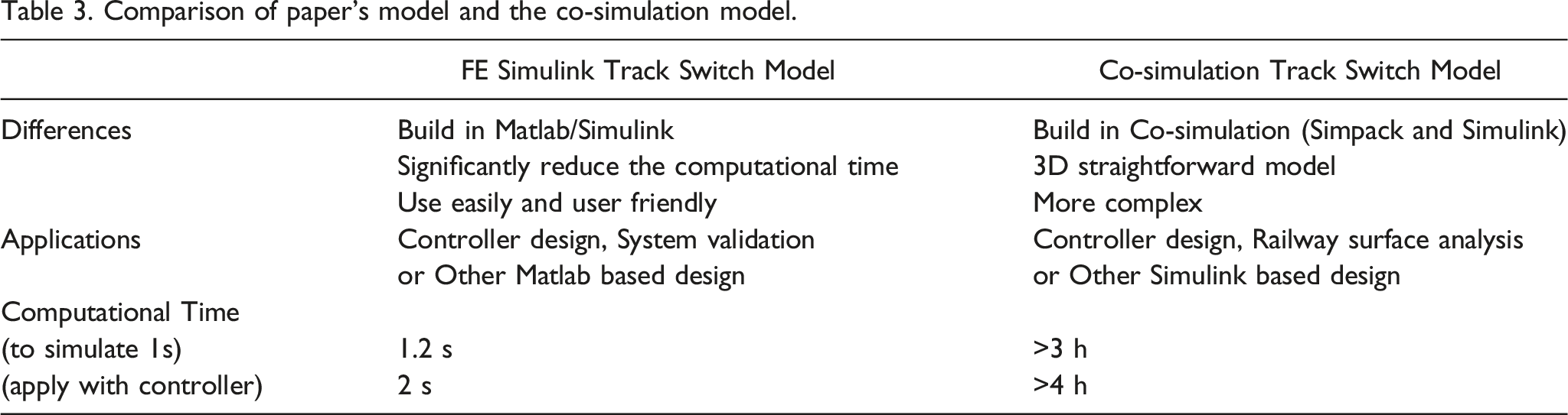
Table 3. Comparison of paper’s model and the co-simulation model.
Conclusion
In this paper, a new approach to the dynamic modelling of railway track switches has been proposed. The model has been described and compared to static and dynamic results obtained using other methods. It has also been shown to be consistent (in terms of static forces and deflections) with experimental results. The outcome is that the model is judged to be valid in that it correctly predicts both the dynamic and static bending of the switch blades. It also has the benefit that it allows actuator forces to be applied along the length of the rails. These positions can be specified by the user/designer. Ultimately it was found that this model operates close to real-time and that it is an order of magnitude faster than similar models developed through co-simulation of MATLAB/Simulink with multi-body dynamics software such as Simpack.
It is intended that this model has a number of potential uses by researchers and engineers. Firstly, it can allow researchers to design, compare and evaluate safely a range of control system designs for railway track switches (which presently are all controlled open-loop). In addition, researchers can use the model to examine actuation options ranging from one actuator to several actuators distributed along the length of the switch. To facilitate these future uses by researchers, the complete model is made freely available and can be found here: https://doi.org/10.25500/edata.bham.00000884 or can be obtained directly from the first author. In terms of future work, we note that it may be possible to model everything in Simpack (i.e. simulate the electro-mechanical actuator and control system in Simpack itself). This is something which could be investigated in the future.
Footnotes
Declaration of conflicting interests
The author(s) declared no potential conflicts of interest with respect to the research, authorship, and/or publication of this article.
Funding
The author(s) disclosed receipt of the following financial support for the research, authorship, and/or publication of this article: The work araised in this paper has received funding from the School of Engineering at the University of Birmingham. The author(s) are deeply grateful to the School of Engineering and Birmingham Centre for Railway Research and Education (BCRRE) for the resources provided.