
Abstract
A dynamic 3D finite element model for the calculation of profile degradation in the switch panel is presented. The model includes the contact between wheel and rail, as well as the contact between switch rail and stock rail to allow an elastic relative movement between the two rails. Break-outs of the switch rail tip can be facilitated by this relative movement and the stresses and strains at this interface are calculated. The profile degradation of the switch rail due to contact loading between wheel flange and switch rail is numerically simulated considering the cyclic plastic deformation of the rail material. The sliding wear is evaluated separately and superimposed to the geometrical change caused by the plastic deformation.
Introduction
Switches and crossings (S&C) are a substantial part of every railway network, which enable railway vehicles to manoeuvre between different tracks. Furthermore, S&C are highly safety-relevant components and need to be inspected and maintained in tight time intervals. As a result, S&C are responsible for considerable acquisition and maintenance costs. 1 Therefore, there is a high level of interest for manufacturers and track operators to increase the underlying knowledge about the most frequently occurring damage mechanisms and pave the way towards a new generation of enhanced switches and crossings in order to optimise the life cycle costs. 2
Especially switch rails are subjected to high lateral impact- and creep forces, as a consequence of the discontinuity they induce in the track. 1 After a high number of loading cycles these contact loads can lead to severe wear and pronounced plastic flow of the rail material. 3 Generally, the contact conditions are more complex in the diverging route and lead to higher lateral contact forces and creepage than in the through route. 4 In recent years, a broad spectrum of research was conducted focusing on the reduction of these severe contact forces by a variation of track parameters5,6 or considering an optimisation of the switch rail profile.7,8
There are multiple parameters which can affect the contact loads and thus the rail deterioration due to the high complexity of the contact situation in the switch panel.9,10 A highly decisive parameter is the position of the initial contact point between wheel flange and switch rail.
11
A premature contact between the wheel and the switch rail can cause high loads in areas where the rail cross section is relatively thin. This can lead to break-outs at the rail tip, which can be seen in Figure 1. The initial contact position between wheel and switch rail is generally determined by geometrical parameters, such as the turnout geometry, the rail and wheel profile, the initial wheel-set position at the turnout entry and the steerability of bogies in the running trains. The wear state of the wheel, which can be described by the equivalent conicity, considerably affects the contact situation as reported by the authors in.
12
A degraded rail profile can cause unfavourable contact angles and lead to a high lateral/vertical force (Y/Q) ratio, which can facilitate train derailments.
13
Vehicle parameters
14
and track specifications
15
have both a major influence on the wheel rail interaction and thus on the contact force evolution. Consequently, it becomes apparent that the investigation of damage mechanisms in the switch panel requires a holistic approach enabling a detailed analysis of the various system interactions. Characteristic break-outs at the switch rail tip.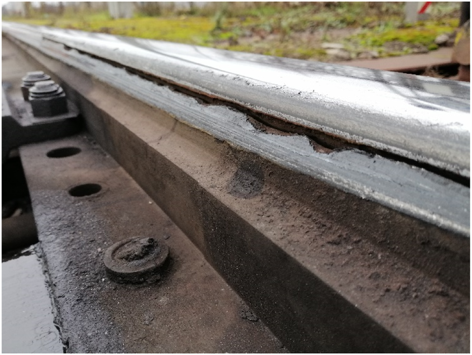
The most frequent damage mechanisms that can be observed in S&C are wear, accumulated plastic deformation and rolling contact fatigue and are therefore subject of numerous publications.16-21 In 22 the authors report that severe wear and plastic deformation are the prevalent damage mechanisms in the front section of the switch rail, where the wheel rail interaction results in a two-point contact between wheel flange and switch rail, as well as wheel tread and stock rail simultaneously. Rolling contact fatigue can be observed in adjacent areas where the wheel is transferred from the stock rail to the switch rail. However, field observations reveal that break-outs frequently occur at the switch rail tip.23,24 These break-outs could be additionally enhanced by the relative motion between switch rail and stock rail and need to be investigated in closer detail, as they are highly critical for the component safety. 25
In order to prevent component failure and traffic disruptions, inspections and maintenance actions need to be executed in fixed time intervals. A scientifically supported development of S&C and an innovative condition-based maintenance strategy will increase the average operating lifetime and reduce the lifecycle costs for the track operators. 26 The current work presents a 3D finite element (FE) modelling approach which is used to calculate the cyclic switch rail deterioration caused by wear and plastic deformation. This work shall analyse the common damage mechanisms in the switch panel and thus provide substantiated knowledge for both track operators and railway component manufacturers.
Method
This section introduces the FE and material models utilised for the numerical calculations and the associated postprocessing modules. The FE analysis is conducted within the commercial software package Abaqus 2019 27 and the postprocessing scripts are coded in Python 3.7.6. The analysis is conducted with a 3D half-track FE model, which is presented in the following section. The analysed switch geometry is a standard 60E1-500-1:12 turnout and the material is a R350HT perlitic steel. The model allows a detailed investigation of the cyclic rail degradation caused by plastic deformation and wear.
Material models
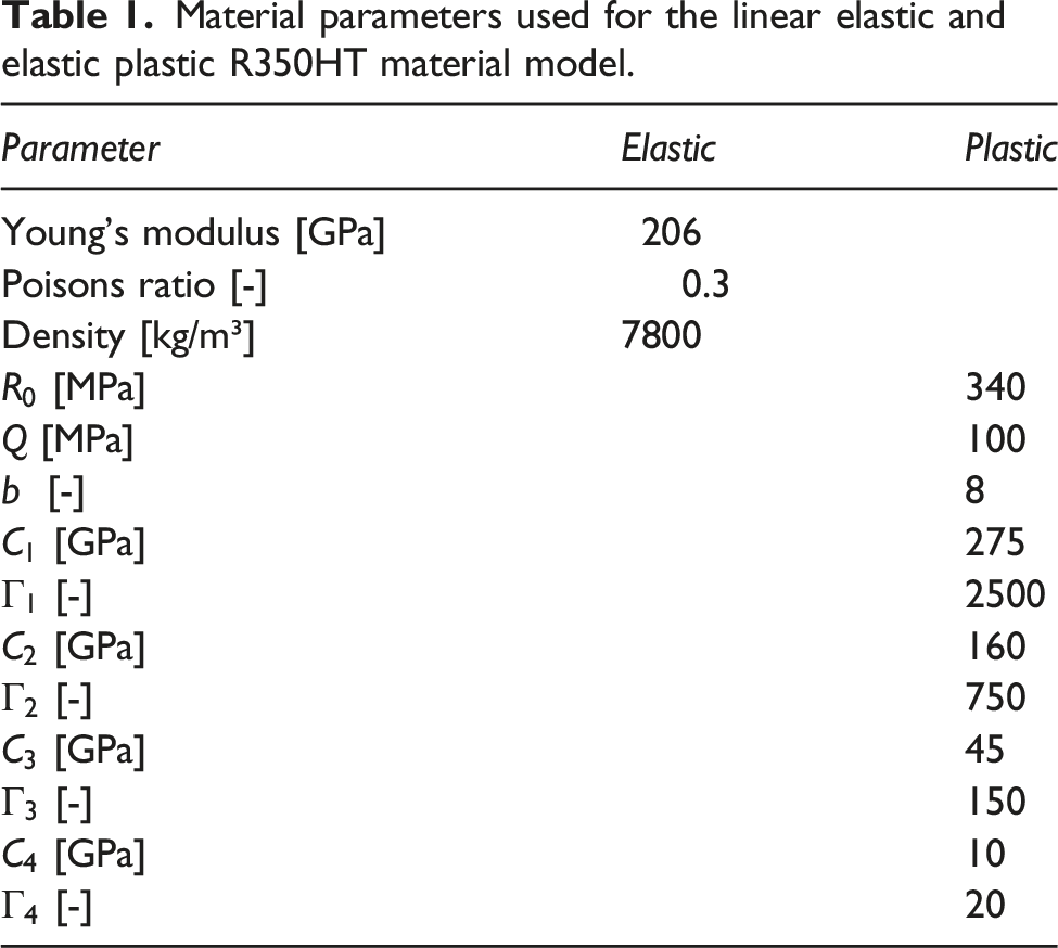
Two different material models are used within this work. For those parts where the profile degradation is not analysed, a linear elastic material model was used, which is described by Hook’s law for elasticity, shown in equation (1). The required material parameters for the linear elastic material model are the Young’s modulus


Cyclic material tests were performed on tubular perlitic rail steel (R350HT) specimens. The tubes were loaded by applying a constant compressive pressure of 600 MPa and a simultaneous alternating (R = −1) twisting moment to achieve a multi-axial stress state in the material. This obtained stress state is assumed to be closer to the real loading situation during wheel-rail contact than standard uniaxial tests. The material parameters are subsequently optimised iteratively in a reversed engineering approach to fit the torque over twisting angle curves obtained from the multiaxial material tests. Four back stresses are used to depict the cyclic stress-strain hysteresis with gradually reduced saturation parameters Torque over twist angle diagrams for the simulated and experimental material response evaluated at (a) 760 Nm and (b) 590 Nm torque amplitudes for the 1st, the 10th and the 100th cycle using a (c) R350HT tubular rail steel specimen with dimensions in millimetre.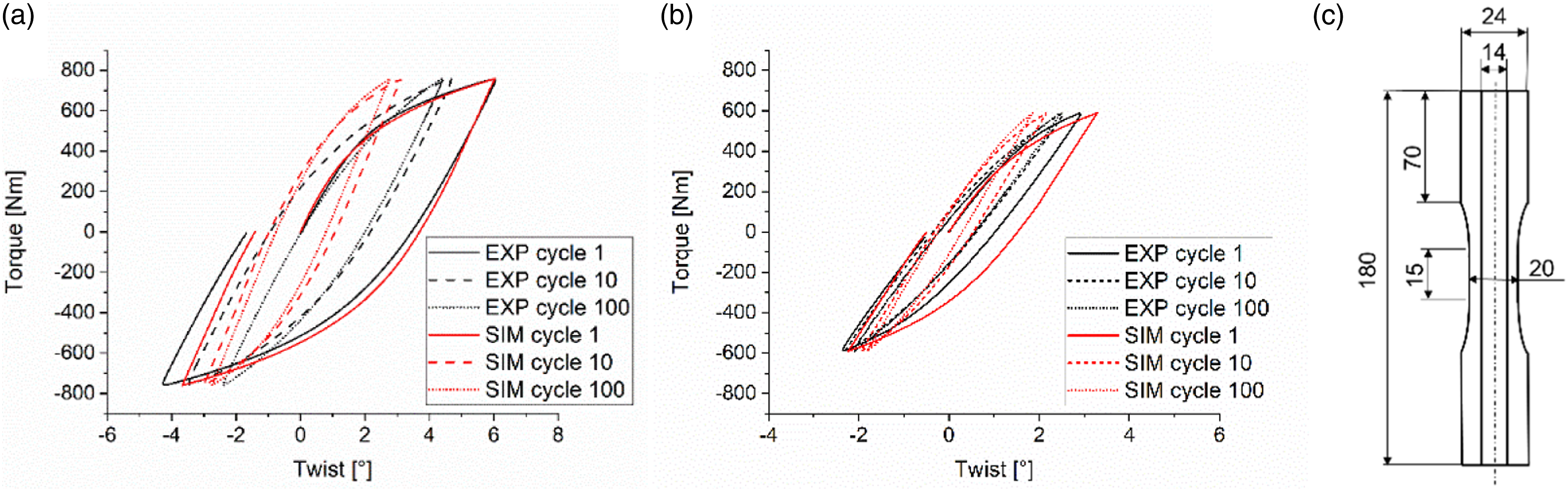
Material parameters used for the linear elastic and elastic plastic R350HT material model.
FE model
The explicit half-track FE model comprises a single wheel rolling over the diverging switch rail and the stock rail. The total model length is 1.5 m and the simulated rolling distance is 600 mm. The introduced model is an advanced development of the full-scale model presented in,
31
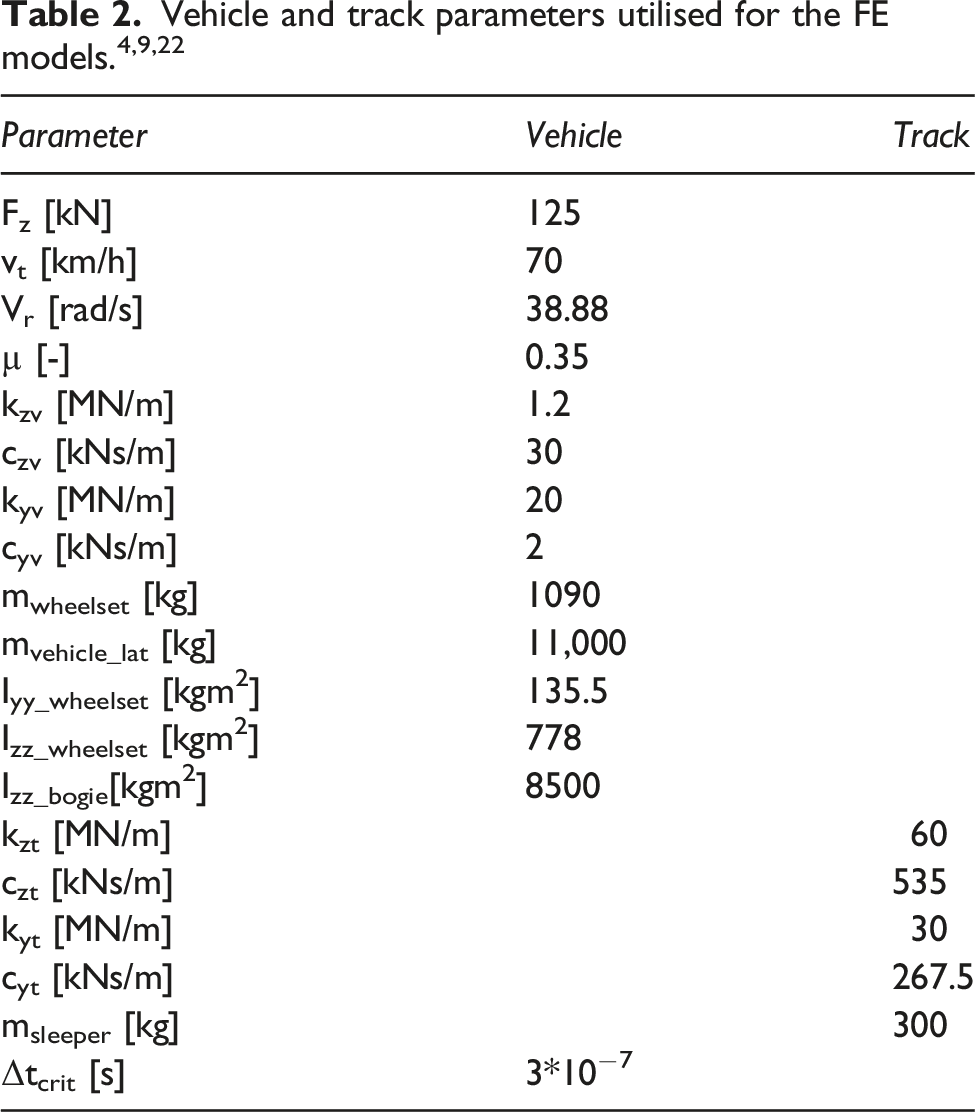
which is validated by means of NUCARS MBD simulations with corresponding track and vehicle parameters. The general contact formulation is used to model the contact between wheel tread, wheel flange, switch rail and stock rail, respectively. Moreover, contact is defined between the two rails to allow for an elastic relative motion. The coefficient of friction µ is set to 0.35 for all contact definitions. The normal contact behaviour is solved by the defining hard contact and the tangential contact behaviour is modelled by the penalty contact formulation, which introduces a penalty stiffness to the contacting elements that is by default 100 times the element stiffness. The vehicle parameters are adopted from4,9 considering a lateral (kyv, cyv) and vertical (kzv, czv) primary suspension of the bogie. To include the vehicle dynamics and provide realistic contact forces, certain boundary conditions are applied to the model reference points (Rp) shown in Figure 3. Rp_A, where the vertical and lateral primary suspension elements are connected to, is constrained in vertical direction and the rotation around the longitudinal and lateral axis are disabled. All other degrees of freedom (DOF) are active. Rp_B is free in all translational DOF and is additionally able to rotate around the vertical axis, which allows a yaw rotation of this point. Rp_C is able to move in all translational directions and can rotate around the lateral and vertical axis. The roll rotation around the longitudinal axis is disabled. Rp_B and Rp_C are coupled to Rp_A with translator connectors, which couple the points rigidly in all DOF except one translational DOF. In this DOF the vehicle primary suspension bushing elements are acting between those points. The simulation starts with a prescribed initial rotational vr and translational velocity vt. Throughout the rolling step vr is kept constant and a static wheel load of 125 kN is applied on the wheel centre point to provide an improved run-in behaviour. The yaw DOF of the wheel is free, which allows the wheel to move in after the contact between wheel flange and rail. The yaw inertias of the wheel-set Izz_wheelset and the bogie Izz_bogie are prescribed on Rp_C and Rp_B to persist against the yaw rotation and provide a realistic yaw response of the wheel. Generally, the wheel is running in the direction of its longitudinal axis. The acting contact forces lead to a yaw rotation, forcing the wheel thereby to follow the track. In addition, the rotatory inertia of the wheel-set Iyy_wheelset is prescribed around the rotational axis of the wheel. The rolling rotation around the longitudinal axis is disabled and therefore neglected in this analysis. The un-sprung wheel-set mass minus the mass of the solid wheel elements mwheelset was attached on the wheel centre point Rp_C and the remaining vehicle mass, which acts on a single wheel mvehicle_lat is attached on the bogie centre point Rp_B, only acting in lateral direction. The track is modelled by means of discrete mass spring damper elements in lateral (kyt, cyt) and vertical (kyt, cyt) direction with an attached sleeper mass msleeper. The reference points Rp_D and Rp_E are fixed in all directions. Rp_F is free in lateral and Rp_G in vertical direction while all other DOF are disabled. The rail surface is coupled to Rp_F and Rp_G via node to surface couplings. In order to allow a vertical and lateral movement of the rail the coupling is disabled at Rp_G in lateral direction and at Rp_F in vertical direction. The corresponding track parameters can be found in.4,22 3D explicit finite element model with applied boundary conditions and constraints.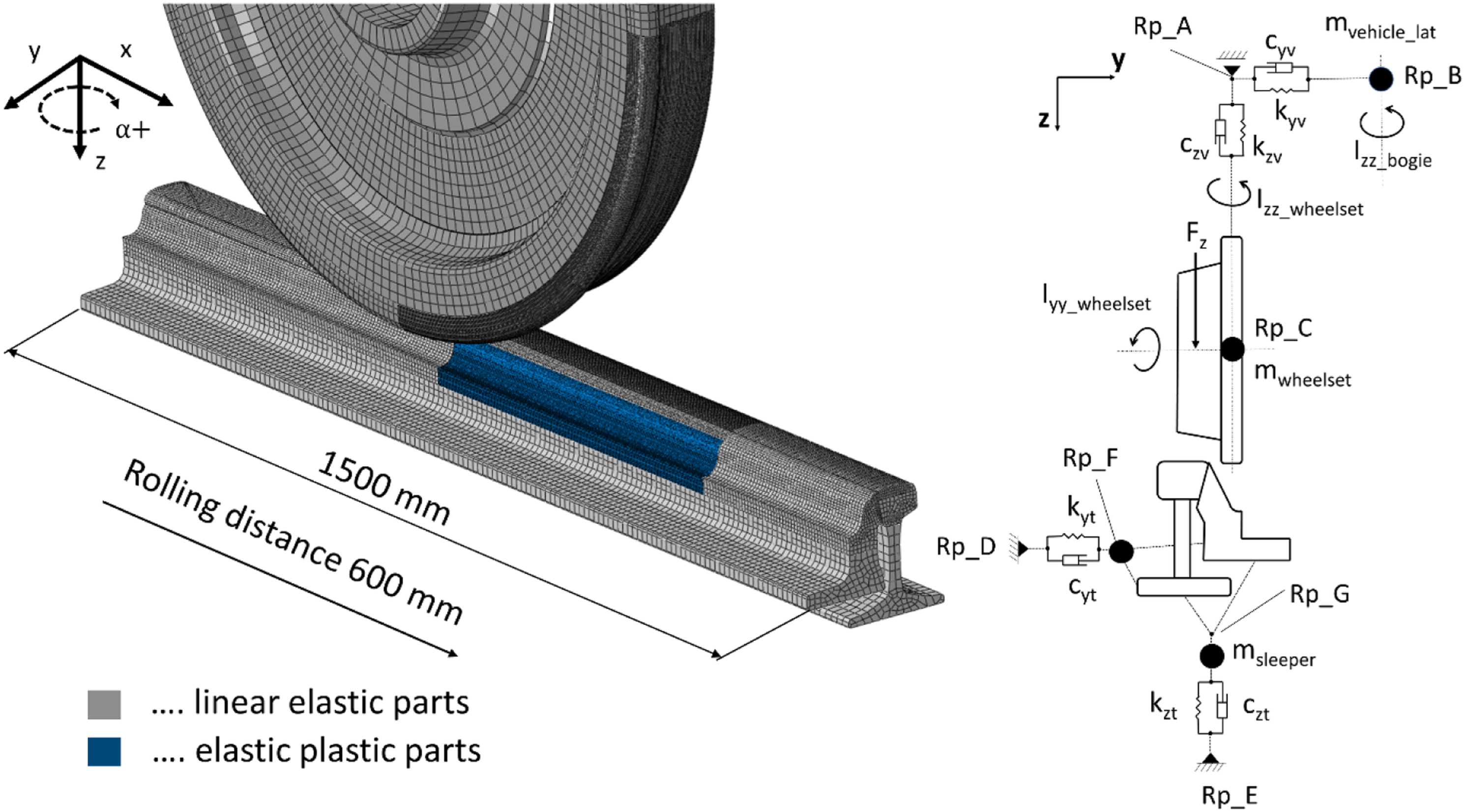
A conducted mesh and mass scaling study has shown that a mesh resolution in the area of contact between switch rail and wheel flange of 0.75 mm is sufficient to resolve the contact stresses. The maximum critical time step is set for this model to Δtcrit = 3 × 10⁻⁷ s, which results in an optimum efficiency to accuracy ratio. The total mass change applied on the model remains below 0.18%. With this set-up one rolling cycle calculated with 16 cores in parallel requires 1 h of computational time. The novelty of the introduced model is that it allows for a dynamic analysis of contact variables considering elastic plastic material behaviour in a cyclic 3D model, with reasonable computational effort. Additionally, the contact between switch rail and stock rail is included to allow for a relative motion and contact loading between the two parts, which allows the investigation of damage mechanisms occurring at this interface.
Postprocessing
Wear
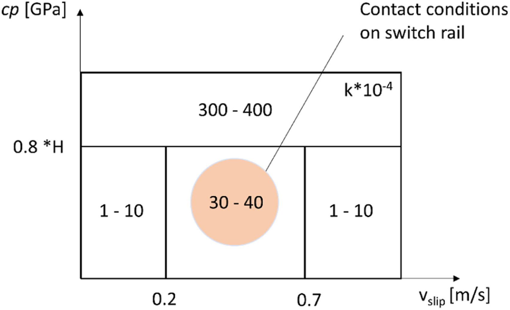
The calculation of the discrete wear depth is computed using the KTH Royal Institute of Technology wear function,33,34 which is based on Archard’s wear law.
35
The required parameters for the calculation of the wear depth KTH wear map
34
utilised for the calculation of the discrete wear depth according to Archard. The wear map shows different contact regions with corresponding wear coefficients.
Plastic deformation
The total strain tensor Schematic illustration of the evaluation of the nodal displacement due to plastic deformation at the switch rail surface.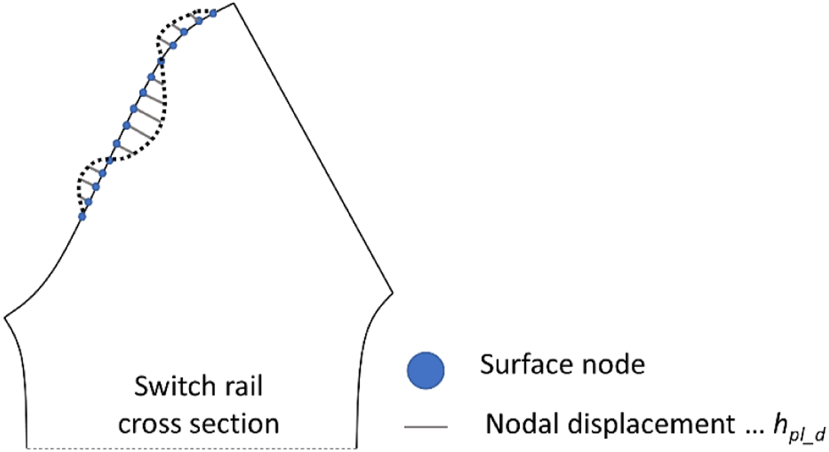
Results
Cyclic switch rail loading
The analysis within this section is performed with the previously introduced model. The cyclic calculations include 10 various wheel profiles of which one is a nominal S1002 profile, three are hollow profiles and six are worn wheel profiles. The utilised wheel profiles are a subset of the 18 wheel profiles measured within the work reported in
1
and are shown in Figure 6(a). Additionally, the initial wheel positions are varied and prescribed for each cycle, see Figure 6(b). The wheel sets and wheel positions are combined so that the wheels impact in the same region (approx. 2m from the turnout entry). The order of the wheels is defined by the wheel profile number (WP1-WP10) and is repeated in the same order. The input files for these 10 cycles are automated and can be replicated as required. In this work the initial 100 cycles were calculated and analysed, starting with a nominal rail geometry and virgin R350HT material. The simulated cycles represent, according to,
31
a set of extreme cases which are assumed to constitute only a small percentage to the total traffic load passing a turnout every day. Nevertheless, as these cases cause high contact loads in areas where the switch rail profile is relatively weak, they can facilitate component failure if the occur repetitively. Figure 6(c) shows the energy dissipation due to frictional work for the first 10 cycles. Figure 6(d) shows the vertical and lateral wheel displacement throughout the first cycle, as well as the yaw rotation of the wheel. (a) Wheel profiles utilised for the cyclic local model calculations and (b) lateral wheel contact forces for loading cycles with various wheel profiles and initial wheel-set positions. (c) The energy dissipation due to frictional work for the first 10 cycles and (d) the kinematics of the wheel centre point for the first cycle calculated with WP1.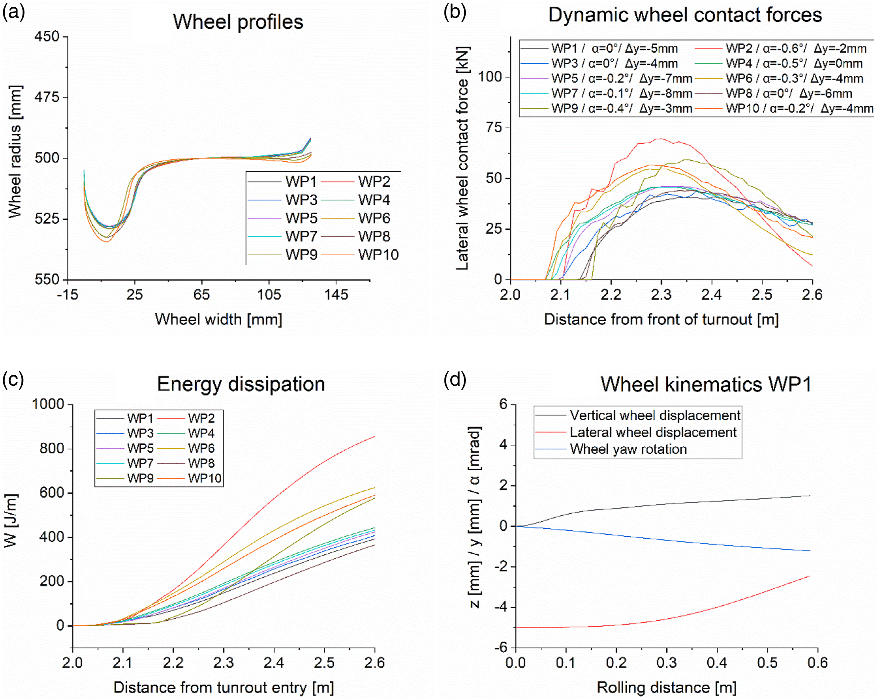
After 100 loading cycles the stress-strain state of the switch rail is evaluated for a specific cross section with high contact loads located at 2.3 m from the turnout entry. Figure 7(a) shows the maximum principal stress during the last loading cycle. It can be observed that the stresses at the surface can reach 2 GPa. Furthermore, the stress distribution at the switch rail/rail stock contact surface yields locally stresses up to 500 MPa in the tensile regime, which is high enough to exceed the fatigue limit of the material.
38
The direction of the highest maximum principal stress at both contact surfaces is parallel to the surface. This means that initiated cracks are likely to grow perpendicular to this surface which can lead to break outs after many loading cycles. Figure 7(b) shows the accumulated equivalent plastic strain (PEEQ) after 100 loading cycles. It can be observed that the maximum equivalent plastic strain yields 0.65 at the rail running surface. In addition, the switch rail/stock rail contact surface is also subjected to stresses beyond the yield strength of the material, which leads to a plastification of the switch rail at this interface. Within this 100 loading cycles the accumulated equivalent plastic strain in this region remains below 0.05. A cyclic accumulation of the plastic deformation of the switch rail in this area can lead to an unfavourable contact surface and increase the stresses additionally. A plastic deformation of the stock rail, which is not considered within this work, could facilitate this effect further. The degradation of this contact surfaces can in combination with the relative movement between the two rails lead to crack initiation and subsequently to crack growth. Hence, it is reasonable to pay attention to this interface during regular inspection and maintenance actions. (a) Maximum principal stress during the 100th loading cycle in a specific cross section. (b) Accumulated equivalent plastic strain after 100 loading cycles in the same cross section.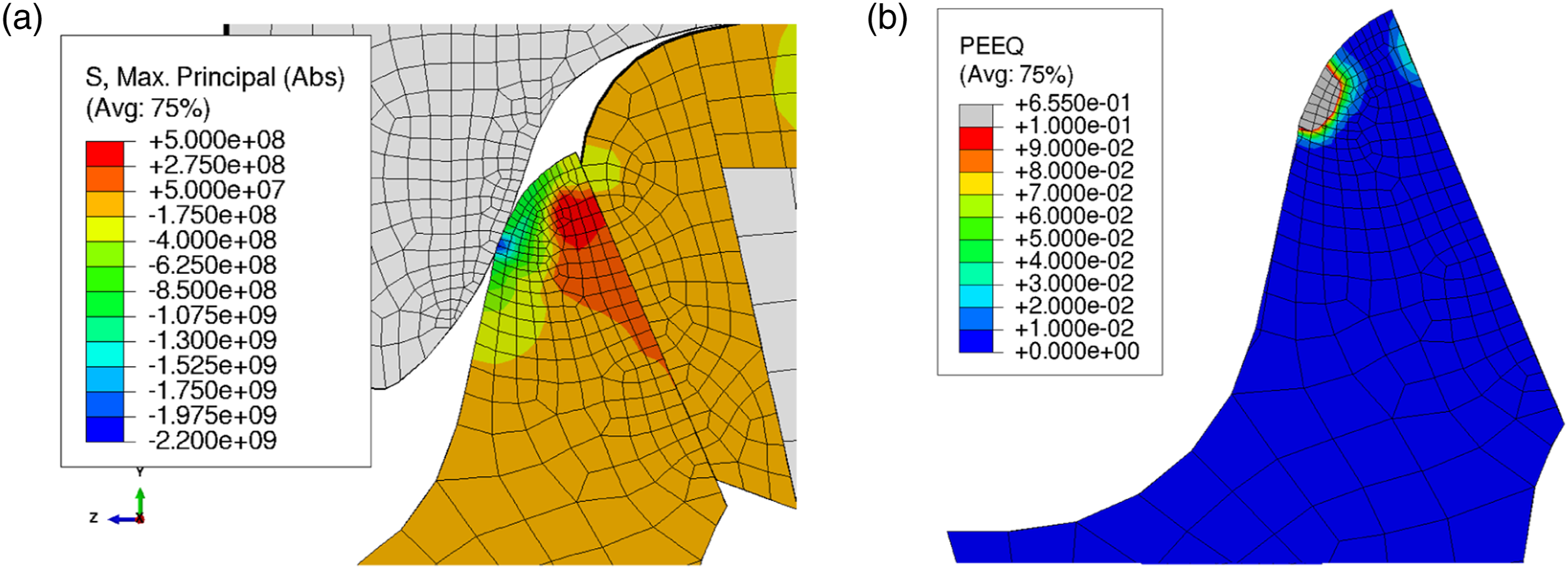
Profile deterioration
The accumulated profile deterioration is mainly governed by plastic deformation and wear of the rail. Within this work a detached approach was chosen, to examine and compare the share each mechanism contributes to the overall profile change. The discrete wear depth and the shape change due to plastic deformation were evaluated as explained in section 2.1 Model descriptions, see Figure 8. It can be observed that the plastic deformation of the switch rail is more pronounced than wear during the initial 100 loading cycles. The plastic deformation causes a wider distributed and deeper displacement of the rail surface than the calculated wear depth. However, this pronounced initial plastic deformation is expected, as the calculations are performed with a nominal rail geometry and virgin R350 HT material. (a) The nodal displacement due to plastic deformation, the wear depth and the accumulated profile change is shown for a characteristic cross section of the R350HT switch rail after the initial 100 loading cycles and (b) a schematic illustration (not to scale) of plastic deformation and wear in a switch rail cross section.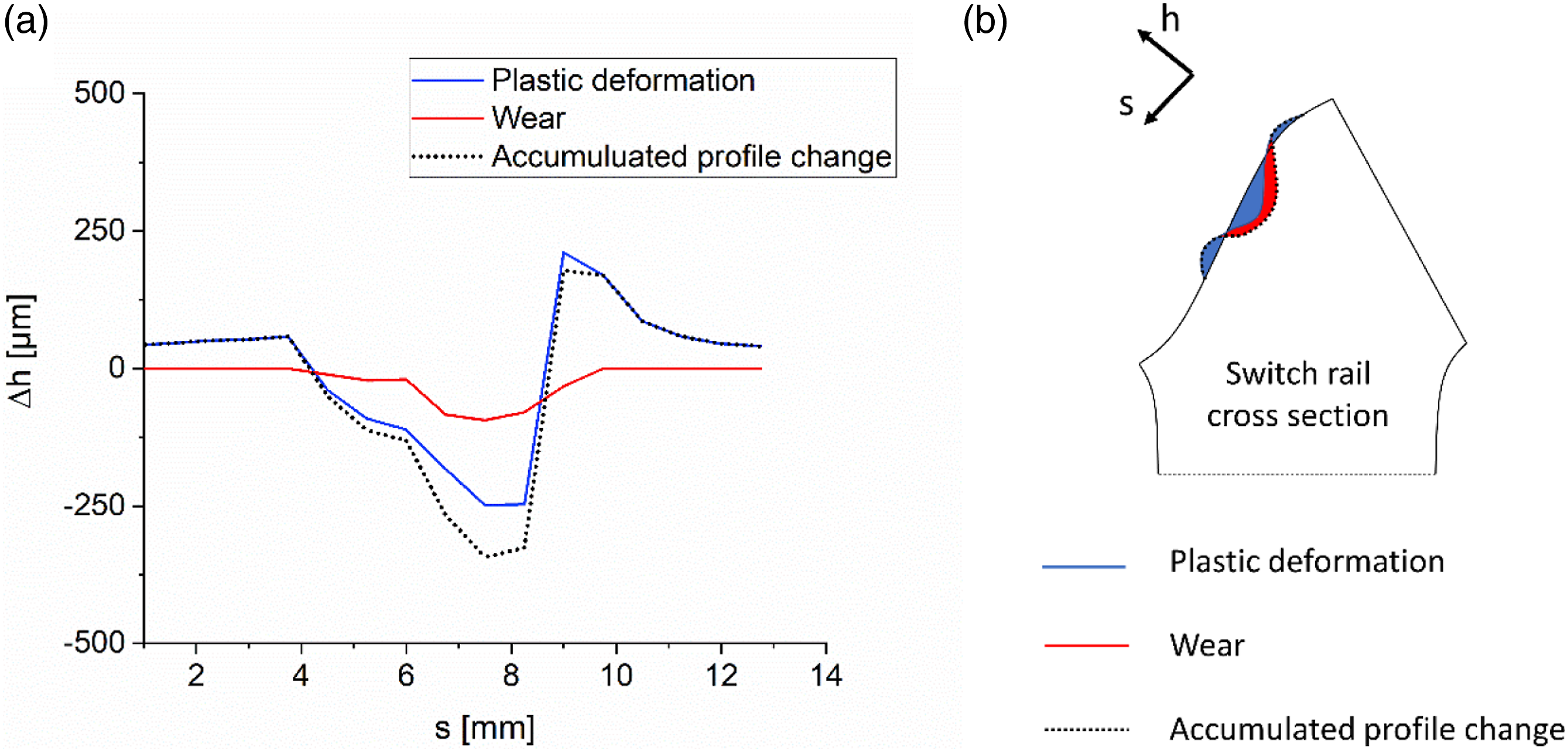
Break-outs
Break-outs of the switch rail tip are a common problem in S&C. Therefore, a detailed analysis of the contact situation at the switch rail stock rail interface was performed. Figure 9 shows the contact pressure and relative displacement at one position located at 2.3 m between switch rail and stock rail during the first rolling step. The evaluation of the contact parameters reveals that the contact situation is less critical in terms of wear due to the low contact pressure and moderate relative displacement. Nevertheless, the loading can be high enough to induce fretting cracks at this contact surface.
39
As wear cannot be expected in this region, initiated cracks can grow into the material and lead to component failure. The maximum principal stress distribution shows that, during the impact of the wheel, the stresses can locally yield up 500 MPa in the tensile regime in areas where break outs are commonly observed. These stresses are close to the fatigue limit and can in combination with the relative displacements lead to crack initiation and crack growth according to.38,40 A more detailed investigation about crack initiation and crack growth leading to break outs is required and shall be performed in future work. Contact situation at the switch rail stock rail interface for nominal rail geometries at a single point during the first loading cycle.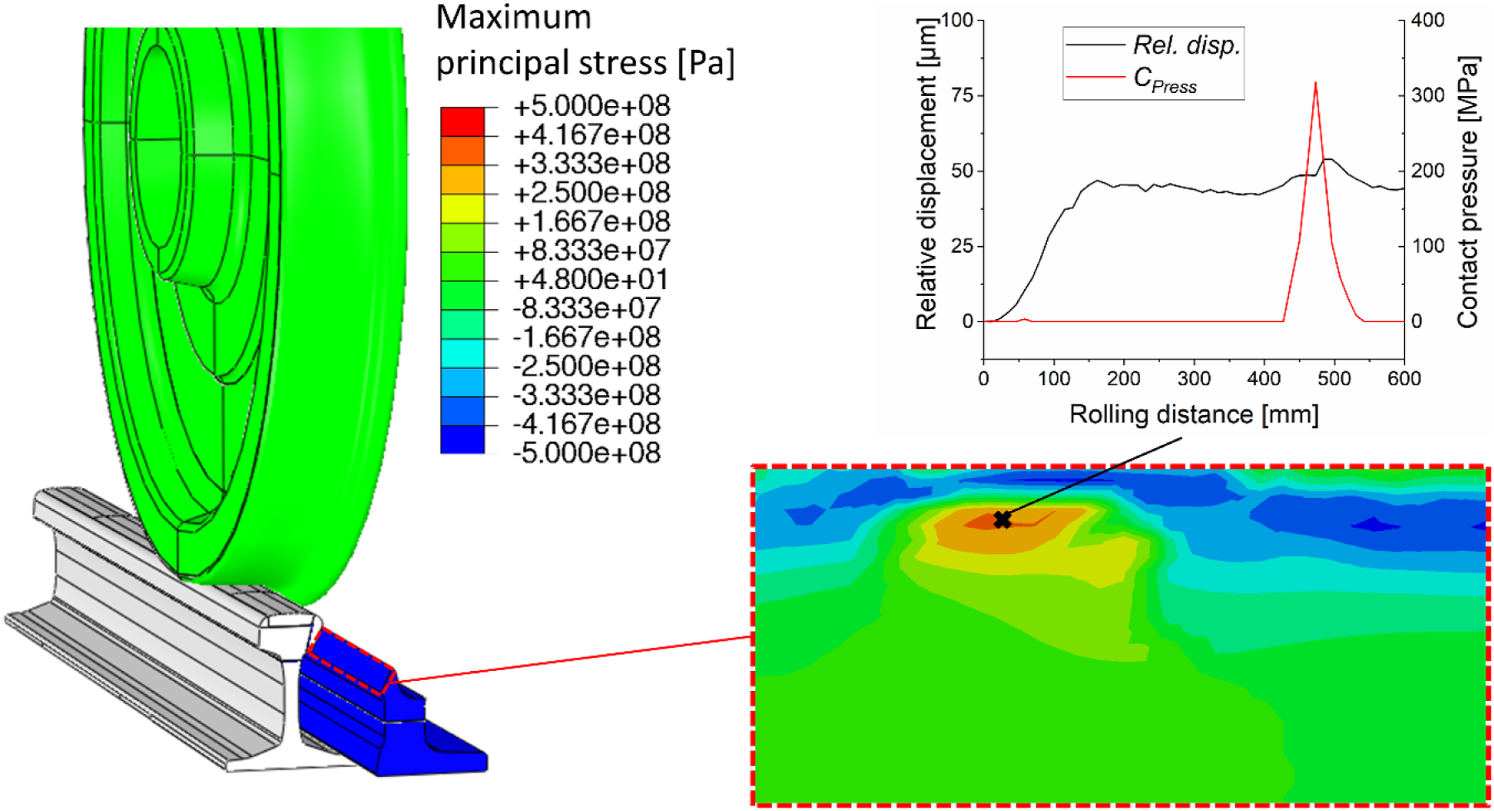
Discussion
The cyclic analysis with the elastic plastic local model shows that the contact stresses caused by the chosen vehicle and track parameters can reach values beyond the yield strength of the rail material and thus lead to plastic deformation and wear of the rail. The accumulated maximum wear depth reaches locally 95 µm and the maximum nodal displacement due to plastic deformation is 248 µm after the initial 100 loading cycles. It was found that the profile degradation caused by plastic deformation is more pronounced at the beginning of the loading history than wear. However, the plastic deformation can also reach shake down with proceeding loading cycles due to material hardening and an adaptation of the rail profile, which leads to an increase of the contact patch size and thus to a reduction of the contact stresses. The proposed model builds the basis for an extended investigation of the long-term simulation of the switch rail degradation.
An analysis of the maximum principal stress components has shown that the stresses around the switch rail/stock rail contact surface can approach critical values regarding the fatigue limit. It is recommended to investigate this part of the switch rail in detail in future work. Geometrical imperfections, such as highly deformed profiles and notches, can increase the stresses significantly and facilitate crack growth leading subsequently to break outs after many loading cycles. The relative movement between the two rails is an additional factor, which is decisive whether wear or crack development will prevail. Future work shall present a method to increase the computational efficiency which allows the investigation of a higher number of loading cycles.
Conclusion
A FE modelling approach enabling the investigation of contact loads, stresses and plastic strains in the switch panel is presented in a novel efficient approach. The profile degradation of the switch rail due to plastic deformation and wear is calculated over the initial 100 loading cycles with various wheel profiles and initial wheel-set positions. The plastic deformation of the switch rail is generally more pronounced than wear within the initial 100 loading cycles.
The calculations show that the stress distribution and the sliding movement at the switch rail - stock rail contact surface can lead to crack initiation in this area similar to fretting fatigue. As with the prevalent contact situation wear cannot be expected developing cracks in this region can grow deeper into the rail and facilitate commonly observed break outs at the upper part of the switch rail.
These results deliver the basis for an optimised switch rail design in order to extend the component lifetime. Further geometrical design- and material parameter studies, which allow for higher profile change until a critical switch rail state is reached, will be presented in a follow up paper.
Footnotes
Declaration of Conflicting Interests
The author(s) declared no potential conflicts of interest with respect to the research, authorship, and/or publication of this article.
Funding
The author(s) disclosed receipt of the following financial support for the research, authorship, and/or publication of this article: The authors gratefully acknowledge the financial support under the scope of the COMET program within the K2 Center “Integrated Computational Material, Process and Product Engineering (IC-MPPE)” (Project No 859480). This program is supported by the Austrian Federal Ministries for Climate Action, Environment, Energy, Mobility, Innovation and Technology (BMK) and for Digital and Economic Affairs (BMDW), represented by the Austrian research funding association (FFG), and the federal states of Styria, Upper Austria and Tyrol. Parts of the study have been funded within the European Union's Horizon 2020 research and innovation programme in the project In2Track2 under grant agreement No 826255.