
Abstract
Advances in rail materials from conventional rail steels to those with higher yield points and the potential of additively manufactured laser clad coatings to improve the durability of railway track components presents a new challenge in characterisation. Many of these new and novel materials have either limited test samples available or are more resistant to strain and therefore present challenges in characterisation. The method reported here uses twin disc tests to simulate cyclic loading experienced by rail steel in service. A sample from a single test condition is analysed, measuring the shear yield stress and the accumulated shear strain at multiple depths below the contact surface, from which a Shear Yield Stress – Plastic Shear Strain (SYS-PSS) relationship is extracted. Knowledge of the stress history of a rail sample is not required to apply the method and minimal samples are required, providing a technique which can be used on rail steel samples removed from service.
Introduction
Rail in service is subject to high compressive and shear loading on relatively small contact areas (around 1 cm2) and a combination of rolling and sliding where it is contact with a wheel. Typically, such loading results in stresses exceeding the rail material’s yield point and consequently in plastic strain occurring. Repeated cyclic loading in this manner can result in accumulated plastic shear strain in a process referred to as ratchetting, leading to large scale plastic deformation within the rail, which, if left untreated, can lead to wear and crack initiation. 1 Regular maintenance of conventional rails, with methods such as grinding, is therefore required to maintain rail safety. Across the UK rail network maintenance of this sort can cause disruption by closing or reducing speeds on lines, reducing network capacity and in 2018–19 cost £1.5bn to Network Rail. 2 The characterisation of the Shear Yield Stress – Plastic Shear Strain (SYS-PSS) behaviour in rail materials is key to describing and modelling this material response to cyclic loading and is the subject of the research reported here.
Conventional rail steels have been developed over the years to improve the durability to the increase in traffic on the network. Materials are now often selected for a certain position in track based on their material properties. For example, rail steels with higher yield points, such as HP3353 and cast manganese are used for high value components such as switches, crossings and tight radius curves to reduce the amount of maintenance required. The application of additively manufactured laser clad coatings has also been shown in lab testing to extend the lifespan of conventional rail.4–9 Such composite material is under development with the aim of being resistant to plastic damage, particularly on high value track components such as insulated joints, while retaining cost and strength advantages of the bulk rail steel. Despite their advantages the material response to load of these materials is not yet fully understood and the effect of ratchetting is not completely eradicated.
Quantifying the behaviour of these materials is challenging as the yield point is much higher than conventional rail steel resulting in less strain accumulation. Secondly, novel materials can have limited availability for testing. 10 A method to characterise the SYS-PSS material response relationship of such materials is presented here in which data is extracted from a minimal number of twin-disc tests. This method is developed for testing novel rail materials in the development stage and also trafficked rail removed from service which can give a greater understanding of how material has performed under service conditions.
Shear yield dependence on plastic strain for BS11 rail steel, which is a softer material than that typically used today, was quantified previously by Kapoor et al. 11 from a series of twin-disc tests of increasing numbers of cycles in a ratchetting investigation. The shear yield stress and plastic shear strain data obtained from rolling-sliding twin-disc tests was compared with results from uni-axial tests and the twin-disc results were shown to be more representative of service conditions due to the high hydrostatic loading of the twin-disc environment. Following tests of differing contact cycles, the rail discs were sectioned and analysed at a depth of 200 µm below the surface and the material response curve was extracted from this. This method is suitable for materials which accumulate large shear strains and which have sufficient quantities available to perform multiple tests. The method requires adapting for newer materials which accumulate much lower plastic shear strain values and for novel materials of limited supply. Its development provides the rail industry a way of characterising any section of rail removed from track, where it is not possible to have identically replicated samples and the rail history would be relatively unknown.
The method developed here uses rolling-sliding twin-disc tests to generate ratchetting within the rail samples from which multiple measurements from one sample are taken at a range of depths below the surface. Fewer tests are then required than previously, yet more data points can be generated. The material response to load is quantified through the SYS-PSS curves produced using this method providing a material characterisation to aid the selection of rail material used in service.
Experimental and analysis methodology
The material response to load was quantified within the following three rail materials to demonstrate the developed test method; (i) conventional R260 grade rail steel, (ii) novel laser clad coating rail material - Martensitic Stainless Steel (MSS) 4 and (iii) the heat affected zone (HAZ) of the R260 grade rail substrate. R260 grade rail steel is known to experience ratchetting in service and was chosen for testing to show how the test method works when a large quantity of data can be easily generated. In contrast the MSS laser clad coating was selected as a novel material for which there was limited knowledge of its material properties. The HAZ of the R260 grade rail steel, created in the additive manufacturing process of the laser clad coating was treated as a separate material as it has properties distinct from the clad or substrate constituent materials.
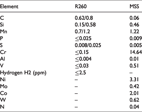
The properties of the MSS laser clad coating, HAZ and R260 grade rail steel were observed prior to testing through a combination of EBSD (Electron Back Scatter Diffraction) and micro hardness measurements. The chemical composition information for the R260 grade rail steel and the MSS laser clad coating is shown in Table 1, from which it can be seen that MSS has a lower carbon content than conventional rail steel, but has additional hardness from carbides and nitrides.
Samples of these materials were subjected to laboratory scale twin disc tests to generate plastic deformation comparable to that which may develop within rail steels in service. After testing, the materials were sectioned and analysed, measuring the hardness and the degree of plastic flow throughout the vertical longitudinal sub-surface plane.
Experimental methodology
Plastic shear strain was generated in samples of the three different rail materials using the Sheffield University ROlling Sliding (SUROS) twin-disc test machine 14 , Figure 1. The bulk of all the test discs was made from R260 grade rail steel, the unclad disc had a diameter of 47 mm. Laser clad discs had a 0.5 mm thick MSS coating formed by grinding back discs clad with a deeper layer, resulting in a disc of 45.6 mm diameter. The HAZ test used a thin 0.15 mm coating formed by grinding back further and had a marginally smaller diameter of 44.9 mm. This thin coating was not expected to be a realistic end application thickness, but was designed to allow the study of the HAZ under contact stress sufficient to drive more extensive plastic flow than when it is protected by a full clad layer. The wheel disc in each test was manufactured from a R8 wheel consisting of ER8 grade steel with ≤0.56 (% by mass) carbon content and 258-296 HB hardness. 15
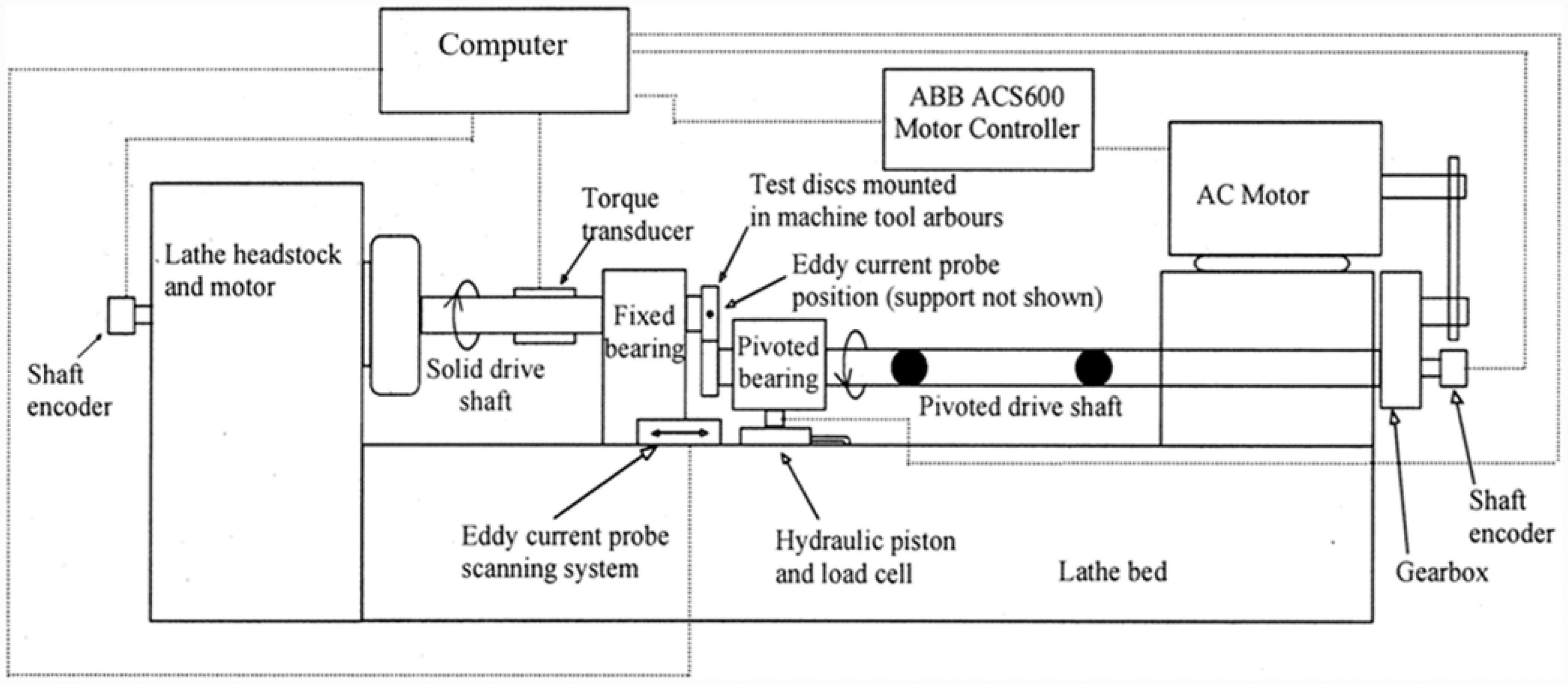
Schematic of SUROS test rig. 14
Twin-disc testing provides a contact replicating key features of the rail-wheel contact, with normal loading replicating the highly compressive stress environment characteristic of rail steel operation, and controlled slip replicating rolling/sliding contact. In combination these are characteristic conditions for generation of both wear and rolling contact fatigue (RCF). Load is applied using a hydraulic piston and monitored with a load cell, this was set to create a maximum contact pressure of 1500 MPa in the tests. The rail disc was set to rotate at a nominal speed of 400RPM with slip (difference in disc surface speed relative to their mean speed) maintained at 1% through variation of the wheel speed, including compensation for difference in disc diameter. A torque transducer monitored transmitted traction for calculation of traction coefficient at the contact. Each of the samples was run for 30,000 dry (unlubricated) cycles, enough to reach steady state, to generate an accumulation of plastic shear strain. Two vertical-longitudinal mid-track samples from each disc were extracted and analysed at multiple depths.
Shear yield stress-plastic shear strain analysis methodology
Following the twin-disc experiments the rail disc samples were sectioned to reveal the longitudinal sub-surface shear strain using standard metallographic techniques to achieve a 1 µm diamond polish finish. DuraScan Micro Hardness laboratory tester was used to measure the Vickers hardness of the sub-surface material at a range of depths using a 0.2 kg load.
Etching was then required to reveal the microstructure of the materials prior to optical microscopy, the type of etchant and time required to reveal the structure was dependant on the material type. For the substrate R260 grade rail steel and the HAZ, the samples were submersed in 2% Nital (98% Industrial Methylated Spirit (IMS) mixed with 2% nitric acid) for approximately 45 seconds The MSS laser clad coating is anti-corrosive and therefore required a harsher etchant solution and longer time. The etchant used was a mixture of 4.8% Nitric acid with the balance of equal volumes of Hydrochloric acid and water. The sample was submersed for around 5 minutes to reveal the microstructure of the MSS laser clad coating.
The plastic deformation was observed using an optical microscope with Buehler Omnimet 9.5 software used to measure the angle of plastic shear strain and the associated depth below the contact surface. Measuring the angle of deformation at a variety of depths which have different levels of plastic flow is where the method differs to previous techniques used by Tyfour et al. 16 in which the strain was only measured at a depth of 200 µm below the contact surface following a series of tests of different durations to generate different extents of plastic flow.
Following measurement, the SYS-PSS relationship is then assembled from independent relationships established for shear yield stress variation with depth, and plastic shear strain variation with depth below the contact surface. This enables the generation of the full SYS-PSS curve from a single sample. The flow chart presented in Figure 2 shows the order in which the main analysis must be conducted in order to obtain the SYS-PSS curve for each material.
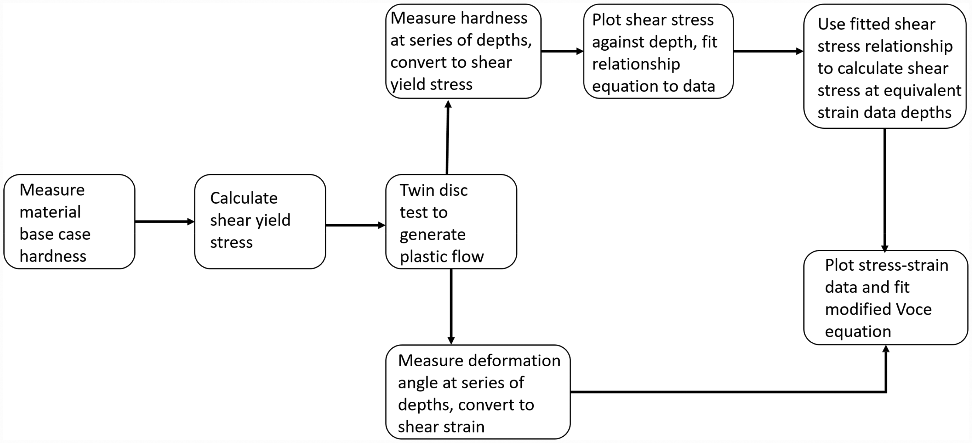
Characterising shear yield stress–plastic shear strain relationship; analysis method flow chart.
Results
Material properties prior to plastic damage
Considering first the rail materials prior to testing, the difference in microstructure of the MSS laser clad coating and substrate R260 grade steel is revealed in the electron back scatter diffraction (EBSD) image in Figure 3(a). The MSS grain structure is significantly refined relative to the R260 grade (MSS grain dimensions approximately one tenth those of R260). The scanning electron microscopy (SEM) images in Figure 3(a) show the grains of grade R260 are, however, larger in the heat affected region just below the MSS layer than they are further from the surface. While this is a qualitative comparison it informs the interpretation of the response to load application quantified below through hardness and plastic shear strain measurements.
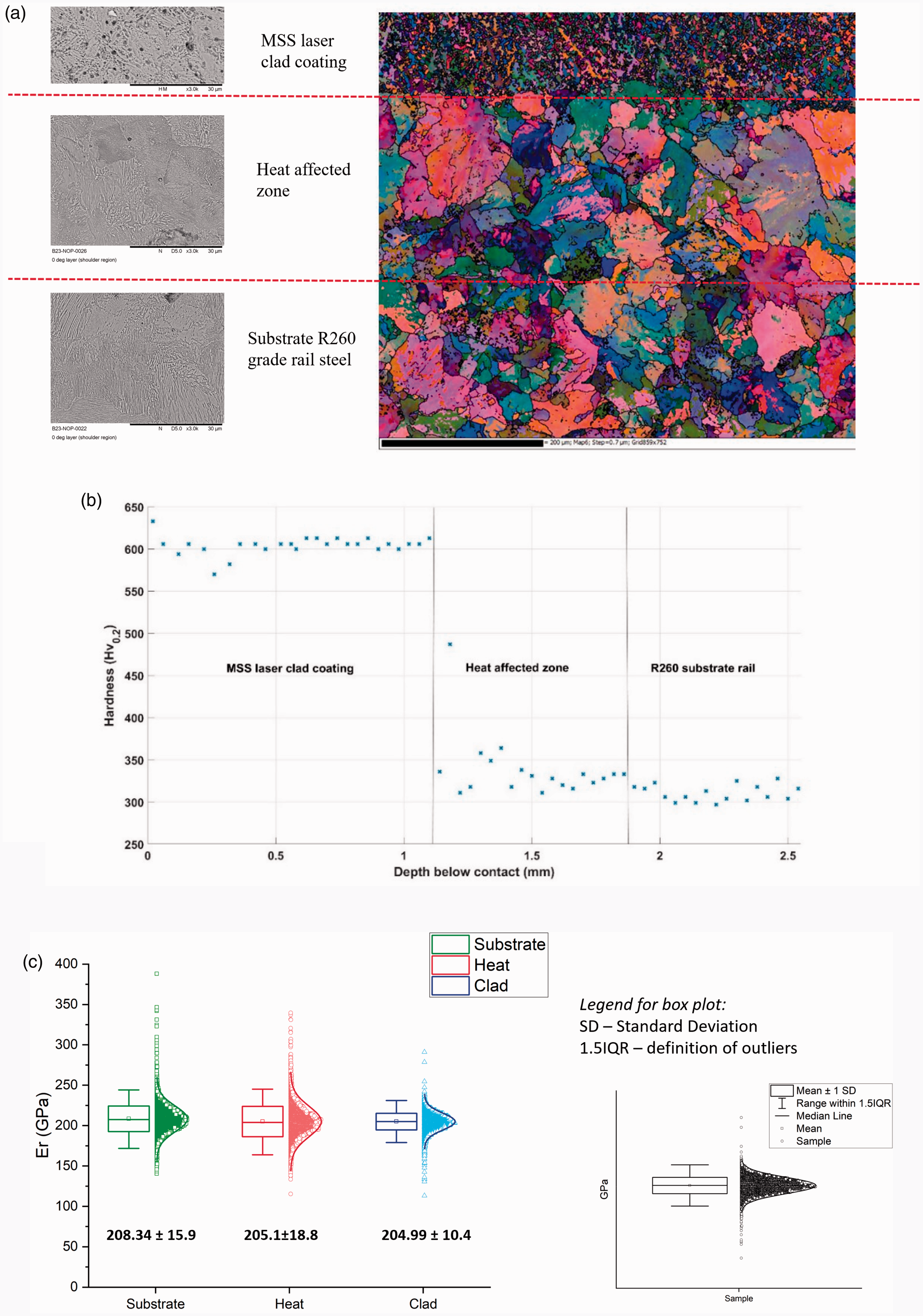
Material analysis of MSS laser clad coating on substrate R260 grade rail steel. (a) SEM and EBSD images, (b) Micro hardness (
Prior to rolling contact micro indentation testing with a 0.2 kg load was used to determine the hardness of MSS, HAZ and R260 grade rail steel using a twin disc sample manufactured with a 1 mm MSS laser clad coating. Results are shown in Figure 3(b), indicating that the hardness of the materials prior to testing differs, with the MSS laser clad coating being almost twice the hardness of R260 grade rail steel. The hardness in the HAZ is marginally higher than in the substrate. On the interface between the laser clad coating and the HAZ a small dilution zone is present, where the two materials are mechanically mixed. This dilution zone is less than 10 µm deep and therefore it is not possible to obtain the material response in this area, the data point at 487
Nano-indentation testing was used to produce load-displacement plots from which the elastic modulus for each material was calculated using the method described by Oliver and Pharr. 18 To obtain informative results from nano-indentation of a structured material such as pearlite, in which microstructural dimensions are large relative to the indent size, property mapping can be conducted to generate a large amount of data points across the material. This allows meaningful interpretation of the findings when individual indents may, for example, fall entirely in ferrite or cementite regions within the pearlite. The Bruker Hysitron TriboScanner was used to create a map of 6400 indents over a 40 µm2 area in the substrate rail, HAZ and laser clad coating. This method used a fast mapping technique with a diamond Berkovich probe calibrated on fused quartz to perform 2 indents per second. The plotted distribution of these data points is shown in Figure 3(c), together with the average and standard deviation of the elastic modulus for each material. 17
Micro indentation hardness results were used as a method to characterise the shear yield stress 
The average shear yield strength results of each material prior to rolling contact testing are presented in Table 2.
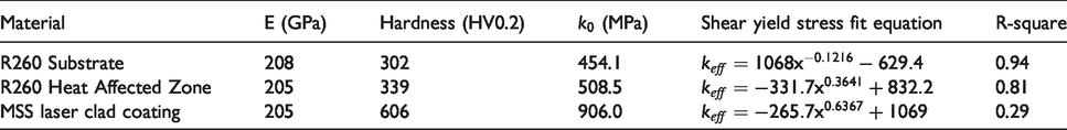
Data for pre-test unstrained materials and shear stress against depth with quality of fit to data.
Coefficient of traction in testing
The tests on the three materials were each conducted in dry conditions with a maximum Hertzian contact pressure of 1500 MPa and a slip of 1% for 30,000 cycles. The coefficient of traction (CoT) was calculated from the measurement of tractional torque between the twin-discs in each test and the results are shown in Figure 4, and is defined as the ratio of traction to normal load transmitted by the contact. The peak CoT in the R260 test was 0.48, this measurement was used as an indicator that plastic damage would be expected within the disc, as ratchetting is recorded in tests conducted under the same dry conditions with a peak CoT of 0.44 by Tyfour et al. 21 For the MSS clad surface, the peak CoT was marginally lower than for the R260 test, the 0.5 mm MSS laser clad coating had a peak CoT of 0.44 and the thinner 0.15 mm MSS laser clad coating produced a peak CoT of 0.43.
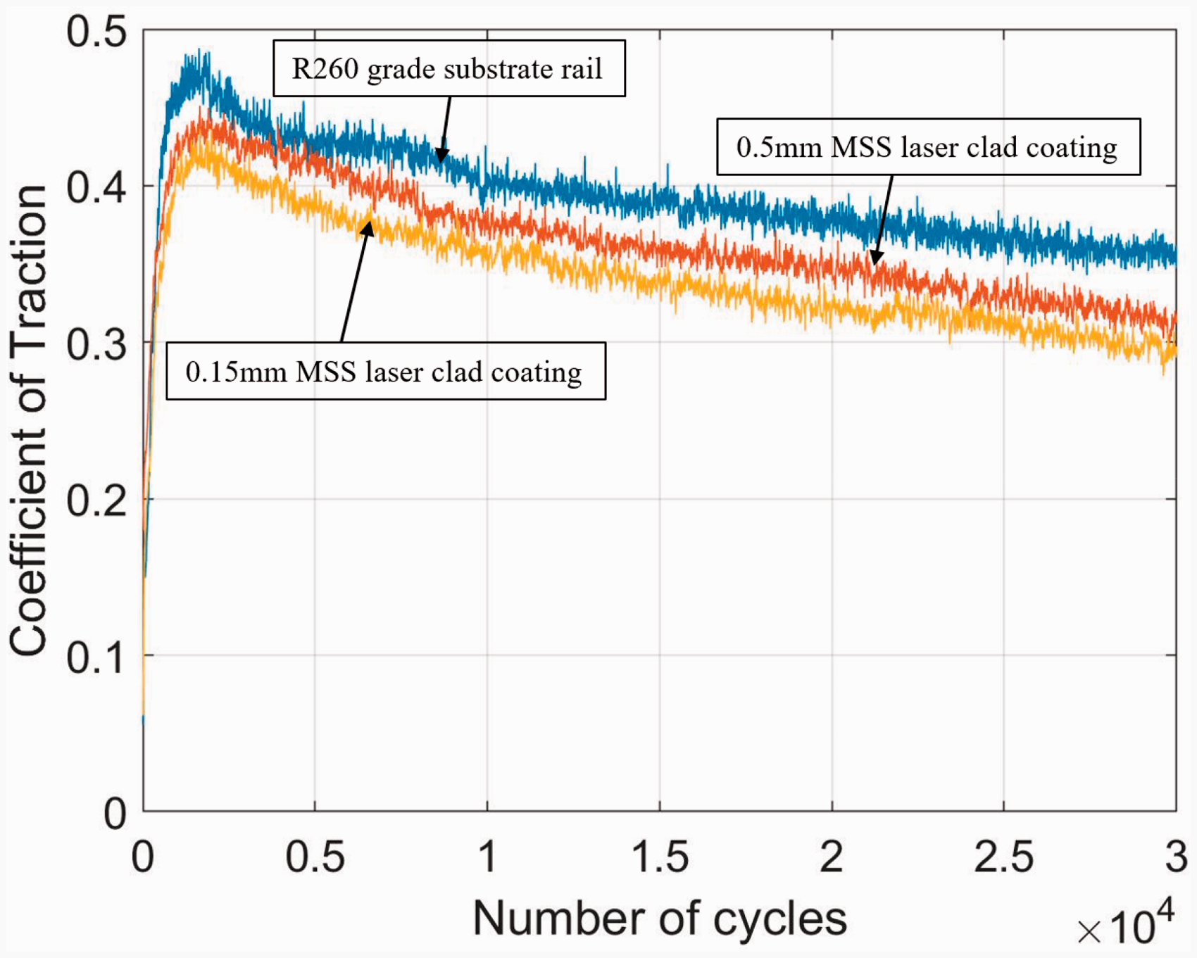
Twin disc test coefficient of traction.
Yield stress variation with depth below the running surface
Figure 5 shows the hardness measured following the twin-disc testing for each of the material samples. Considering the data points closest to the surface, Figure 5(a) shows that the R260 grade rail steel hardened by up to 69%, this beneficial behaviour being one reason pearlitic steel is attractive for use in rail applications. Figure 5(b) shows some hardening in the HAZ at the same test conditions of up to 33% at the interface which can be explained by the near surface material in the HAZ specimen being protected by around 0.15 mm thickness of MSS laser clad coating. The MSS laser clad coating itself was found to have increased in hardness by only 13%, the shallow nature of the plastic flow meant that fewer data points could be collected in this case.
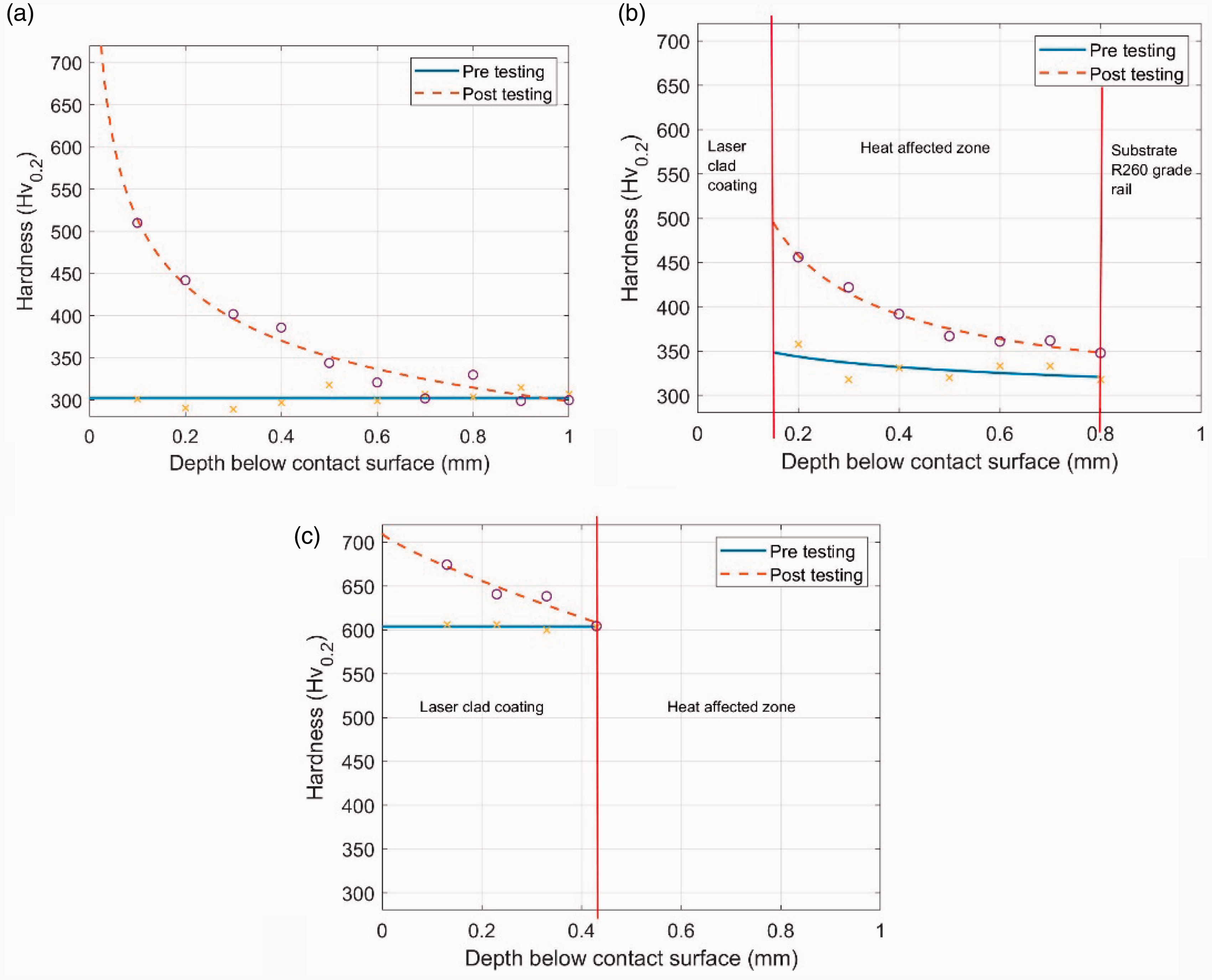
Work hardening results (a) Substrate R260 grade rail steel, (b) HAZ and (c) MSS laser clad coating.
The shear yield stress 
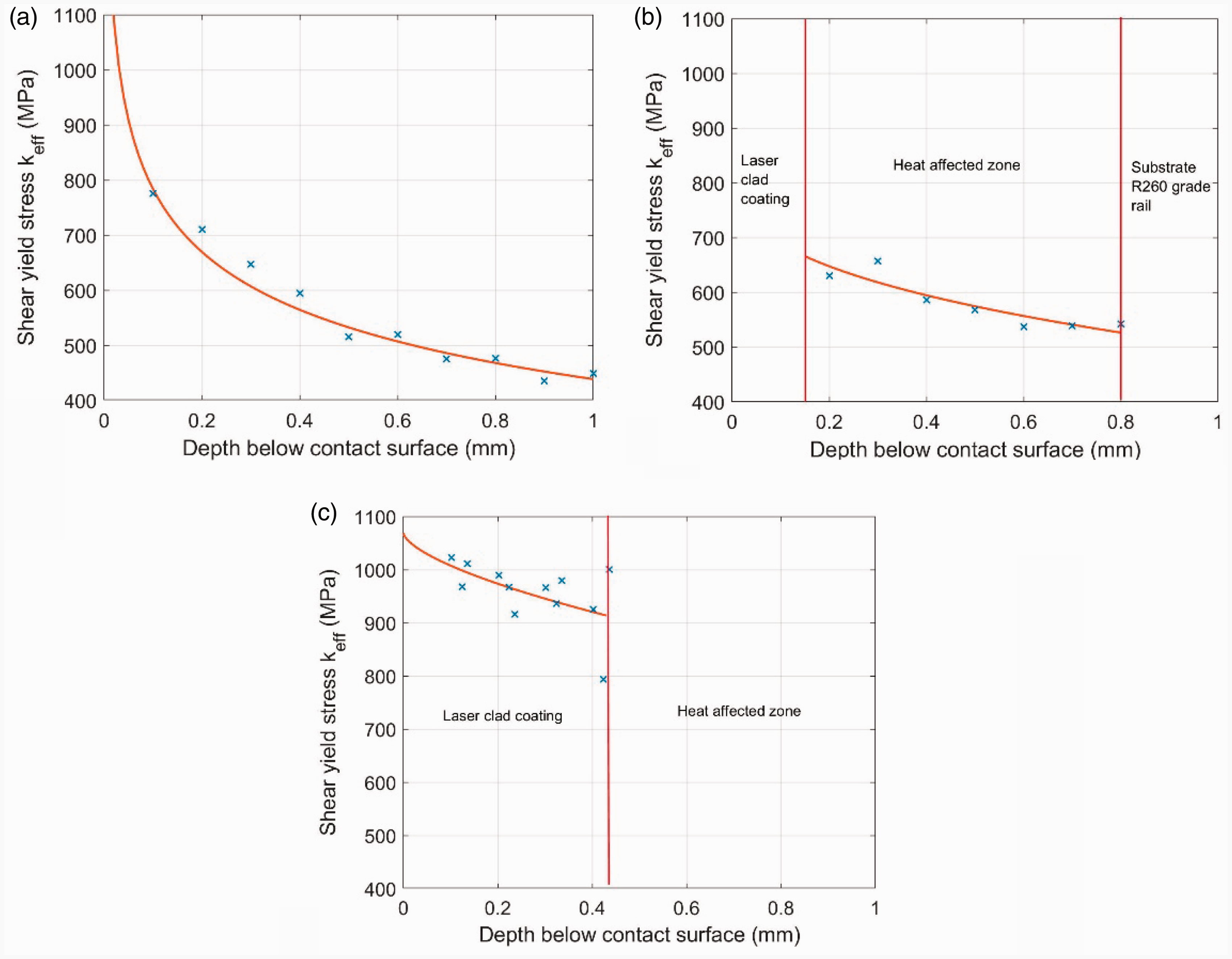
Shear stress against depth fits (a) Substrate R260 grade rail steel, (b) HAZ and (c) MSS laser clad coating.
A line of best fit was plotted through these results to give an equation for shear yield stress plotted against the depth below the contact surface for each material, shown in Table 2.
Strain variation with depth below the running surface
Plastic shear strain was quantified through the measurement of the plastically deformed microstructure at a range of depths below the contact surface of the samples, using the tangent to the angle, equation (3).
This is a similar approach to that used in previous investigations 16 and 11 in which shear strain was measured at a single depth. The developed method examined strain at a range of depths from the running band illustrated in Figure 7(a) rather than at a single depth from the running surface as conducted previously. This provided information on a range of plastic strains from a single sample whereas previously this was achieved using many samples run for different durations. While there is a significant advantage in the reduced number of samples needed, the evolution of strain with number of contact cycles cannot be determined from a single test. However, as long as test duration is sufficient to take the material to ductility exhaustion evidenced for example through crack initiation, it is able to determine the end point of the strain accumulation process. Examination at a range of depths is also more appropriate for cases in which materials change with depth, such as crossing from the clad layer to the HAZ and then the substrate. Collecting data at a single fixed depth would be unlikely to adequately capture properties for this case.
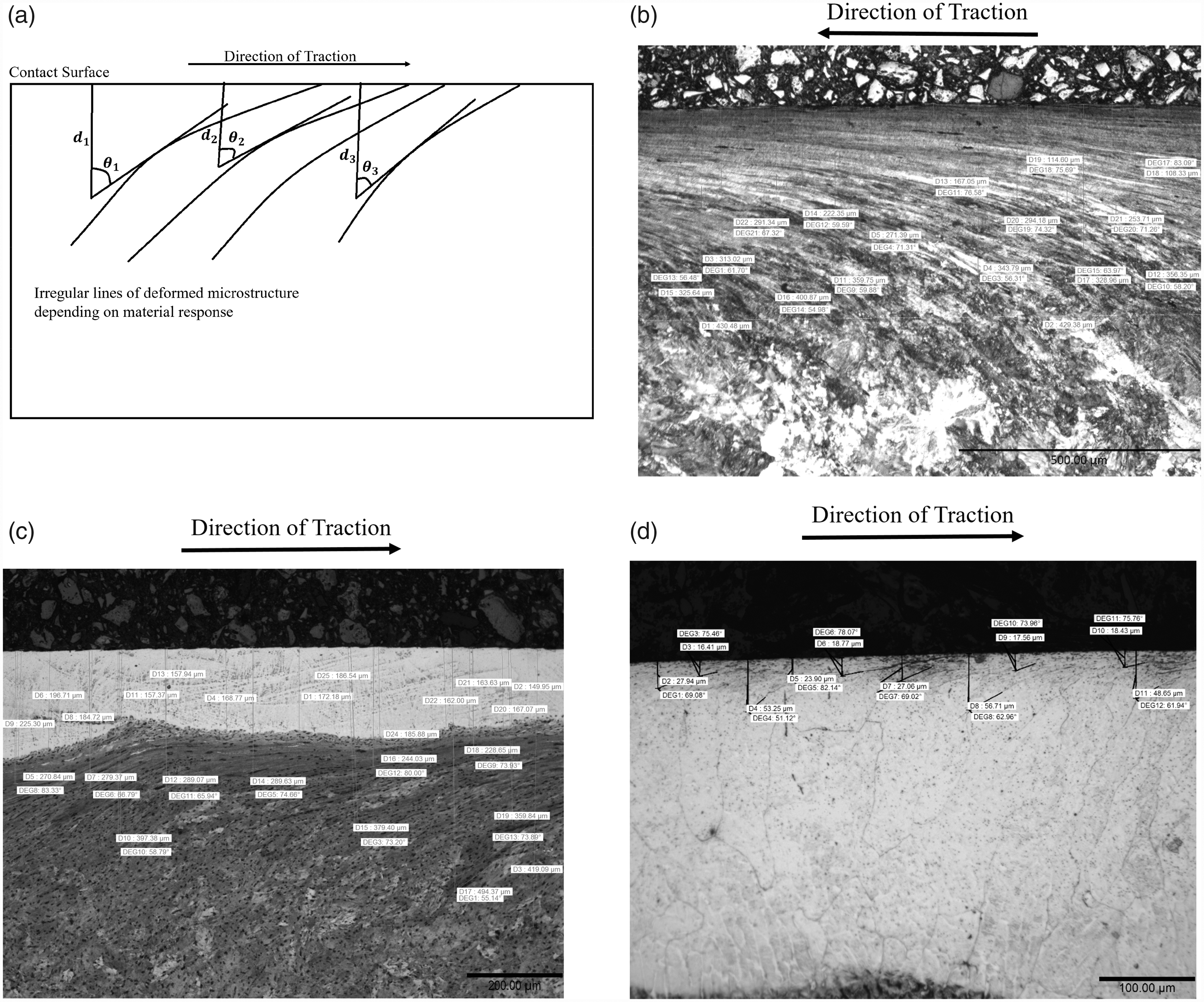
Plastic shear strain angle measurements, (a) measurement method with variable depth, (b) substrate R260 grade rail steel, (c) HAZ and d) MSS laser clad coating.
Measurements of the deformed microstructure were estimated to have an uncertainty of ±0.5° due to the variation of deformation with depth. With the test conditions used, the R260 grade rail steel was found to accumulate the greatest plastic strain of the materials tested, providing the data points in Figure 7(b). The HAZ and MSS laser clad samples were found to be more resistant to accumulation of plastic shear strain and it was only possible to collect around 10 data points for each of these materials (Figure 7(c) and (d) respectively). This is still double the number of data points previously found satisfactory for defining material behaviour in BS11 normal grade rail steel. 11 The thin clad present in the HAZ specimen was particularly useful for understanding how the cladding may ‘scale up’ to full size rail wheel contacts, illustrating that a coating that is thin relative to the contact stress field size will allow plastic strain accumulation in the substrate below the cladding as shown in Figure 7(c). Importantly, it was found that despite the significant substrate plastic strain accumulation the cladding showed no sign of de-bonding or separation.
Critical strain is the plastic shear strain magnitude at which the material fails through a ductility exhaustion process.
22
In previous work this has been found through development of a steady state wear rate during a series of tests of increasing duration.
21
In the current tests the aim was to extract this information from the limited test samples available, with each test being run to sufficient duration that cracks had begun to initiate at the surface. The angle of plastic deformation at the point of crack initiation, where a crack had subsequently propagated to the surface, was used as the indicator of critical ductility exhaustion failure strain. In the MSS laser clad coating a crack initiation plastic strain of around 86°(±0.5°) was detected indicating a critical strain
Extracting the SYS-PSS curve
Using the equations in Table 2, the shear yield stress was calculated at the depths for which the strain data had been recorded enabling the SYS-PSS relationship to be correlated. Considering the estimated uncertainty in plastic strain measurement of ±0.5° the SYS-PSS data plots with error bars are presented in Figure 8. A modified Voce equation, equation (4), was fit to the data points for each material
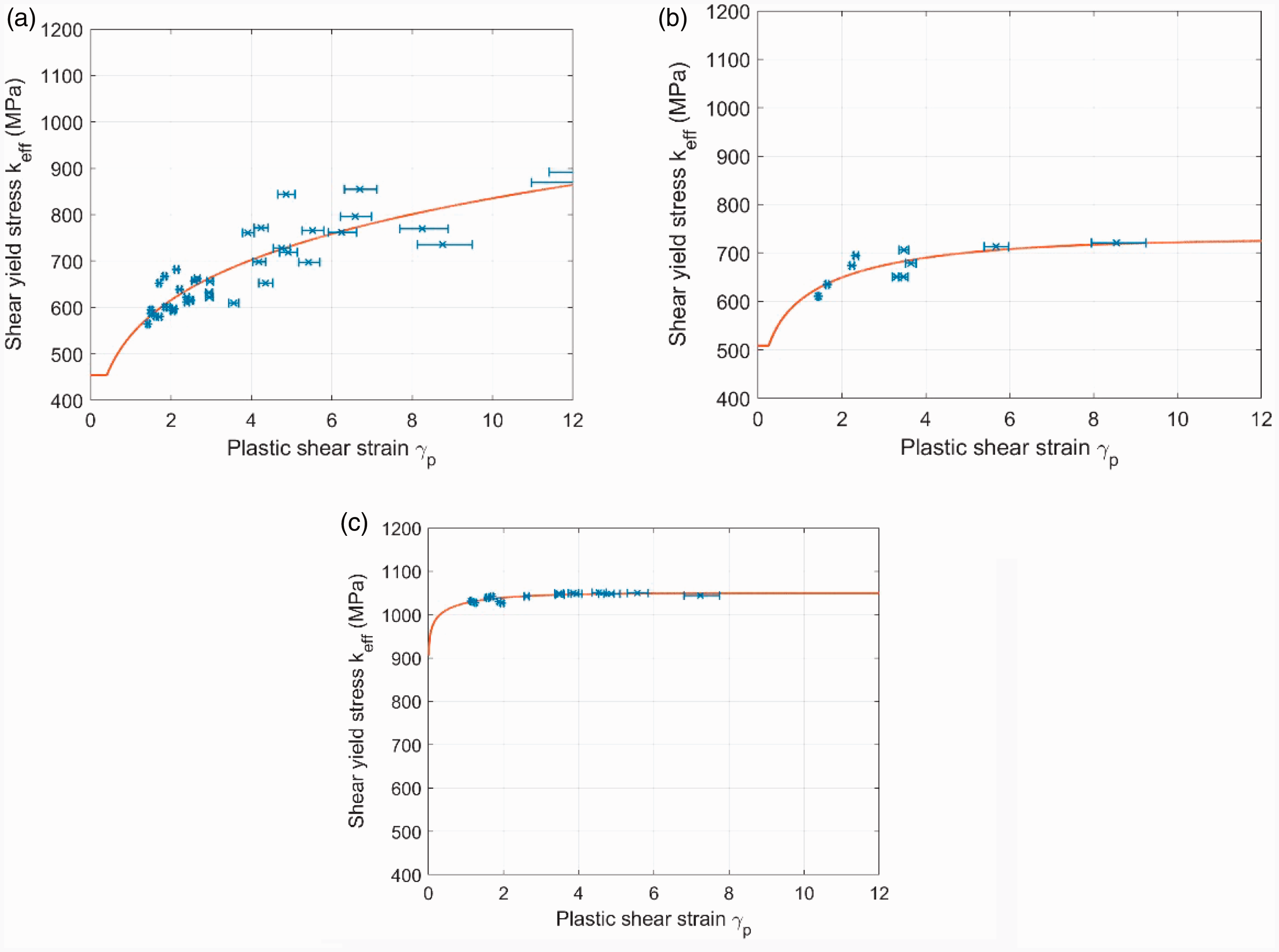
SYS-PSS material response behaviour results above initial shear yield stress (a) R260 grade rail, (b) HAZ and (c) MSS laser clad coating.
Discussion
Experimental and analysis techniques were developed and used to measure the SYS-PSS behaviour and material properties of R260 grade rail steel, HAZ and MSS laser clad coatings using a single test condition. The results fit to the modified Voce equation (equation (4)) which was also used with the results for BS11 rail steel by Kapoor et al. 11 using the multiple test technique of increasing cycles.
The laser clad MSS coating showed evidence of plastic flow only very close to the surface (Figure 7(b)), with correspondingly shallow variation in sub-surface hardness after testing. Despite the limited depth of plastic deformation its magnitude very close to the surface was comparable to those reached in R260 and HAZ materials. The shear yield stress of the MSS laser clad coating following cyclic loading is the highest of the materials tested and it is the most resistant to ratchetting.
The HAZ is protected by the thin layer of laser clad coating and has a higher shear yield stress than the uncoated R260 grade rail steel. Some plastic deformation was present in the HAZ material sample below the 0.15 mm coating (Figure 7(c)) but not in the substrate rail of the MSS sample with the 0.5 mm laser clad coating, indicating that strain may accumulate in the HAZ if the depth of laser clad coating is insufficient. The R260 grade rail steel accumulates higher strain values at lower shear yield stress than the HAZ or MSS, Figure 8(a).
Since the shear yield data and quantification of plastic flow are independent of any knowledge of the applied stress that generated the flow, the developed analysis techniques are applicable to rail materials removed from track with visible plastic deformation. In the current case the near surface MSS shear strain is likely to have been driven by surface roughness stress to result in accumulation of plastic shear strain despite the high yield stress of the material, while the greater depth of deformation in the R260 is a bulk stress effect. Despite this difference in cause, the SYS-PSS relationship can still be derived. The analysis could be conducted on the materials directly without running twin-disc experiments, although measurements on unstrained material would be required using part of the material free from deformation, e.g. well below the running surface.
Conclusions
A material response to load characterisation method has been developed in which a rail material sample from a single twin-disc test can provide all required data to derive the respective SYS-PSS curve. The method was demonstrated for conventional rail steel in addition to a highly ratchetting resistant MSS laser clad coating on a R260 grade rail steel substrate. The test and analysis method described was appropriate for all of the materials and the results were comparable to previous, more time consuming test methods.
The MSS laser clad coating has a much higher initial shear yield stress than standard pearlite rail. It was found that plastic flow was confined to a shallow surface layer reaching only 57 µm from the running surface indicating it will be highly ratchetting resistant in service. The HAZ is also shown to be resistant to ratchetting, however the depth of MSS laser clad coating is a crucial factor in material performance. The results indicate that if it is applied too shallow then the substrate rail will accumulate plastic shear strain below the interface.
Following the analysis method flow chart in Figure 2, the material response to cyclic loading in modern rail steels can be measured. There is the expectation that rail samples taken from within track can be characterised in this way as the material response is independent of the loading history. In this case the twin disc testing would be eliminated from the analysis method. If the rate of strain accumulation rather than its steady state is required, then additional tests of intermediate length will still be required.
Footnotes
Declaration of Conflicting Interests
The author(s) declared no potential conflicts of interest with respect to the research, authorship, and/or publication of this article.
Funding
The author(s) disclosed receipt of the following financial support for the research, authorship, and/or publication of this article: This project is funded through Industrial Case (Cooperative Awards in Science and Technology) studentship number 17100018 with the EPSRC (Engineering and Physical Sciences Research Council) National Productivity Fund and Network Rail.