
Abstract
In order to further reduce the vibration of vehicles and simultaneously increase ride comfort, a class of new control strategies, namely, the extension of Rakheja-Sankar (RS) control, is proposed for semi-active suspension systems with magnetorheological (MR) dampers of high-speed trains. At first, the design and analysis of semi-active control strategies are conducted in a quarter railway lateral model considering the node stiffness. Secondly, a whole vehicle model of a high-speed train is constructed by using Universal Mechanism (UM) software to be applied in evaluating semi-active control strategies. Finally, a hardware-in-the-loop (HIL) test system is carried out to verify the performance of the new control strategies. During these processes, the transmission characteristics are calculated and compared, which helps to test the performance of the semi-active control strategy on train vibration suppression. Then, the effect of the control strategies on the dynamic performance of the whole vehicle is studied. The ride comfort under different control strategies is compared, and the effects of different semi-active control strategies on the lateral stability and safety of trains are also analyzed. Through simulations and experiments, it is confirmed that the new control strategies can effectively reduce the lateral vibration of trains and therefore contribute to the improvement of ride comfort while they do not significantly reduce the train running stability and safety. Therefore, the new control strategies possess future application value.
Keywords
Introduction
The passive suspension system on vehicles has the advantages of low cost, easy installation and maintenance, and stable performance. The damping and stiffness coefficients of a passive suspension system are obtained by matching and optimizing the vehicle parameters and the specific track lines. Under most running conditions, they can effectively reduce vibration. However, the damping force cannot be adjusted in real time with changes in track lines and vehicle parameters. Under a certain relative speed of suspensions, only a fixed damping force can be provided. 1 Therefore, passive suspension is less adaptable to changing track lines, and the ability to decrease vibration is significantly reduced over a certain level of irregularity. In short, the passive suspension system has been unable to meet the requirement of attenuation of vehicle vibration. If an active device that generates the control force is added to the suspension system and the control force is adjusted by the designed control algorithm, the purpose of reducing the vibration of vehicles will be achieved, and an active suspension system will be formed. Moreover, compared with a passive suspension system, an active suspension system can adjust the stiffness and damping coefficients dynamically and adaptively according to some changing conditions, such as the vehicle’s motion state, track line conditions, and loads, which will contribute to keeping the railway vehicles in a good state of vibration suppression.2–5 Many experts have been studying active control technology to achieve a better dynamic performance of railway vehicles.6–9 For instance, in order to further improve the curving performance and stability of the train, an active control system was designed using simulation and experimental analysis by Braghin F and Bruni S to replace the original yaw damper. 6 An active control technology applied to the car body tilting was introduced by Persson R and Goodall RM, which is helpful for curve passing of railway vehicles. 7 In order to improve ride comfort, an active lateral secondary suspension with the H∞ control method was established and simulated by Orvnas A and Stichel S. 8 Active suspension systems can realize multi-objective optimization through control methods, actively adjust suspension parameters, and compromise the ride comfort and running safety of railway vehicles. In summary, the active control has strong adaptability and can bring excellent dynamic performance for vehicles. 10
American scholars Crosby and Karnopp proposed the concept of semi-active control technology in the 1970s, and the control mode was applied to actual vehicles in the early 1980s. 11 It is also called passive active suspension because of its lower dependence on external energy. The semiactive suspension system is very different from the passive suspension system. The damping coefficient of semi-active suspensions can be adjusted in real time by using various intelligent dampers (magnetorheological dampers), which only need very little external energy. Controllers and sensors are also necessary in semi-active suspensions except intelligent dampers. Through these, the semi-active suspension system can be adapted to the changing track conditions. Compared with the active control, its structure and maintenance are simpler, therefore its cost is lower. The vibration attenuation performance of the semiactive suspension is obviously better than that of the passive suspension, while it is weaker than that of the active suspension. Although the semi-active system performance can not be on a par with the control performance of the full active, it still enjoys wide application prospects. 12
At present, semi-active control technology is developing rapidly and is applied in many fields, such as automobiles, railway vehicles, and buildings.13–16 In 1983, the “on-off” semi-active suspension developed by Toyota, which can generate the corresponding damping force by adjusting a switch, was applied in the 280GT car.
In 1985, a Formula One racing car with semi-active suspension designed by Dominy and Bulman came out. In 2014, a semi-active suspension system with variable damping and variable stiffness developed by Yutong Bus Company greatly improved the ride comfort of cars. In order to verify the performance of the semi-active control on vibration reduction and improvement of ride comfort in high-speed trains, vehicle tests were conducted by Japanese railway vehicle engineers on 500 series EMUs at 300 km/h on Sanyo Shinkansen Line. 17 The results showed that the lateral acceleration of the vehicle body and its energy spectrum decreased significantly. The semi-active suspension has gradually become a standardized device in Shinkansen vehicles in Japan since then. In addition, semi-active control technology has also been widely used in structural vibration control. In the future, with the rapid development of science and technology, the semi-active control technology will be more and more widely used, which will bring huge benefits for society.
To date, various semi-active control strategies have been developed for adjusting damping coefficients.18–20 Superior control strategies used for semi-active suspension systems can further reduce the vibration of vehicles. For example, it is easy to implement the famous Sky-Hook (SH) control strategy, which has been widely used due to its superior performance in the reduction of vibration and improvement of ride comfort. Hence, many experiments about the semi-active control strategies have been conducted, and a variety of transformations have been produced until today.21,22 In 1985, Rakheja and Sankar found that when the damper’s damping force and the spring’s elastic force were in the same direction, the damper force should be controlled to zero or a minimum to reduce the vibration acceleration of the vehicle body. Therefore, the Rakheja-Sankar (RS) control strategy is proposed according to this idea.23–25 Based on optimal control theory, Savaresi et al. made a significant improvement on the traditional SH control strategy and proposed the famous control strategy of acceleration-driven damping (ADD). 26 Similar to the SH strategy, the ADD strategy has a very simple mathematical expression. Savaresi et al. proposed a hybrid control strategy (Mix-SH-ADD) based on the frequency transfer characteristics of the SH control strategy and ADD control strategy. 27 The advantages of SH and ADD are combined in this strategy. Therefore, theoretically speaking, it can achieve the best control effect.
The subject of this paper is the design and simulation of semi-active control strategies based on a railway vehicle model. It is worth noting that the paper focuses on the basic form of each control strategy, namely, the switch mode. There are three purposes that should be fulfilled when the paper is finished. The first objective is to propose an improved RS control strategy through comparative analysis of the vibration transmission characteristics with the traditional semi-active control (SH, RS, ADD, etc.).
The second aim is to establish a UMMATLAB co-simulation model of a high-speed train and simultaneously study the influence of various control strategies on the dynamic performance, such as ride comfort, safety, and stability. The third purpose is to conduct a hardware-in-the-loop test and apply the semi-active control strategies in a real MR damper to explore and analyze the effects of various control strategies on the reduction of car body vibration.
A quarter vehicle model considering node stiffness
A quarter railway vehicle lateral model is established to study the lateral vibration by using train parameters in this section because the research objects of this paper are railway vehicles. At the same time, the node stiffness is considered in the connection part of the two ends of the shock absorber.
28
For the convenience of calculation, the node stiffness of the two ends of the shock absorber can be equivalent to a series stiffness,
29
which is shown in Figure 1. A quarter railway vehicle lateral model.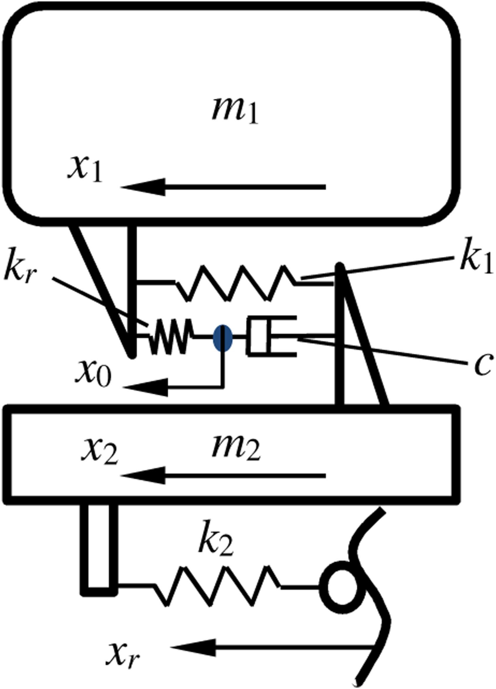
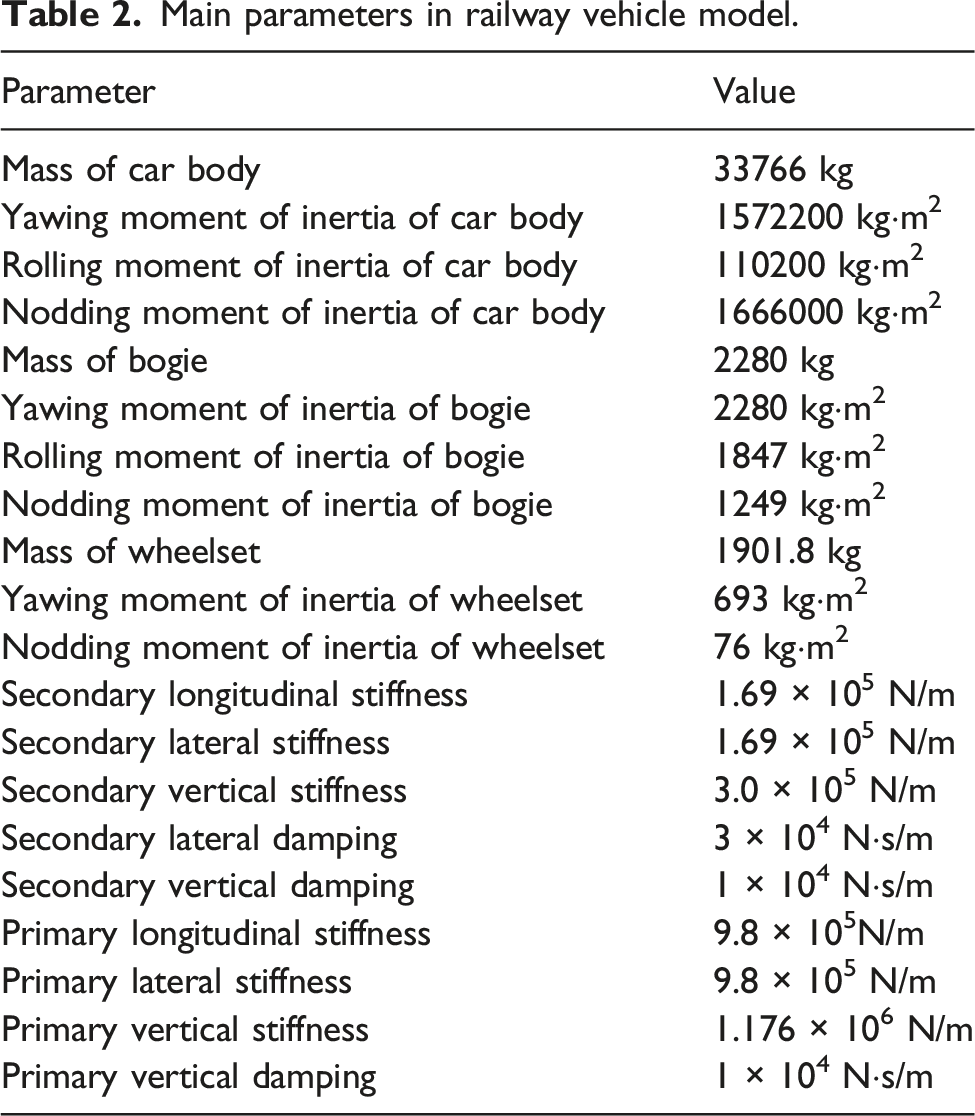
The model mainly contains two parts, namely, the car body and the bogie, also known as the secondary suspension system. The parameters used throughout the paper are derived from a type of high-speed trains: m1 = 8441.5 kg, m2 = 1140 kg, k1 = 168.9 kN/m, k2 = 13,000 kN/m, k r = 8575 kN/m, and c = 30,000 Ns/m.
In these parameters,m1 and m2 are the masses of a quarter car body and half of the bogie, respectively. k1 is the lateral stiffness of the secondary spring, k2 is the lateral stiffness of the primary spring, k
r
is the node stiffness in series, and c is the passive damping coefficient of the secondary lateral damper. The differential equations of motion of the model are established as follows
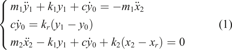
The equations of the model are solved numerically by using MATLAB/Simulink, as shown in Figure 2. Simulink model.
Design of control strategies
Rakheja-Sankar control strategy
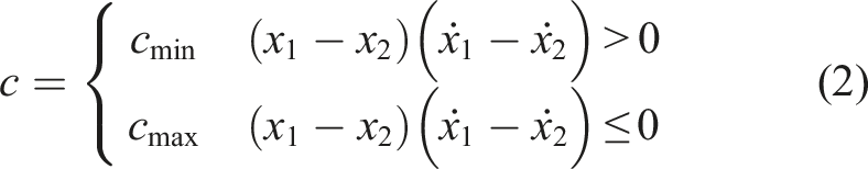
The conventional RS control strategy was proposed by Rakheja and Skankar,
24
the expression of which is as follows
To analyze the semi-active control strategy on the acceleration frequency response of the vehicle body, a method is used. It can provide clear frequency domain pictures about the attenuation capabilities of suspensions. Then, the vibration suppression effect of the control strategy is evaluated. The function formula of this method is as follows26,27,30
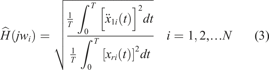
In order to numerically compute the function, the following procedure has been used: The closed-loop system is fed with a finite set of N single frequency excitations: x
ri
(t) = Asin(w
i
t), i = 1, 2,..., N, t = [0,T]. The corresponding output signals are recorded:
In Formula (3), Acceleration transfer characteristics.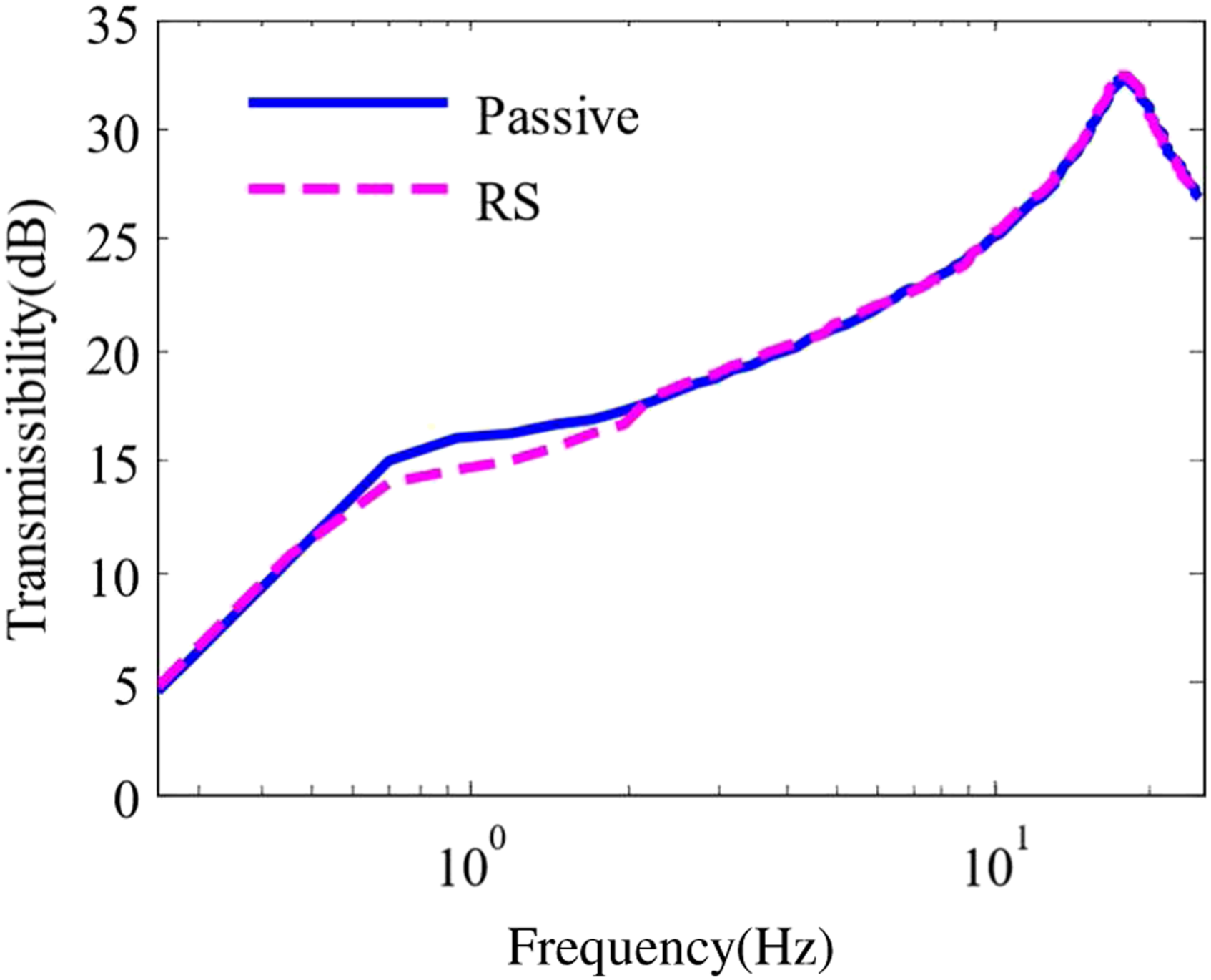
The effect of the RS control strategy on vibration reduction at low frequency is better than that of passive control (uncontrolled). In the following research, the paper will improve it to be superior.
Rakheja-Sankar-I control strategy
In this section, the vehicle body mass block is taken as the research object, and the node stiffness is neglected. By this assumption, the following equation can be obtained

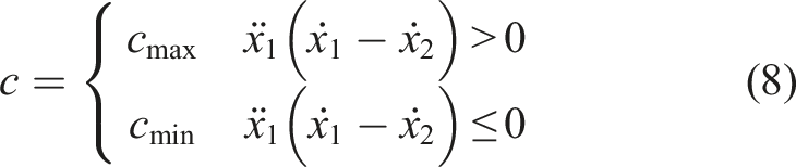
The acceleration is affected by both the spring force and the damping force. For the RS control strategy, when the spring force and the damping force are in the same direction, that is
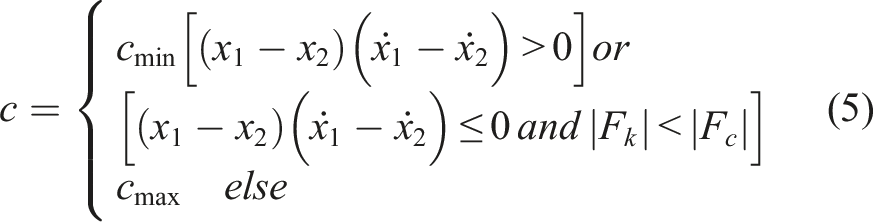
where
In this paper, c0 is selected to analyze the transfer characteristics of the improved RS control strategy. The results are shown in Figure 4. Analysis of acceleration transfer characteristics.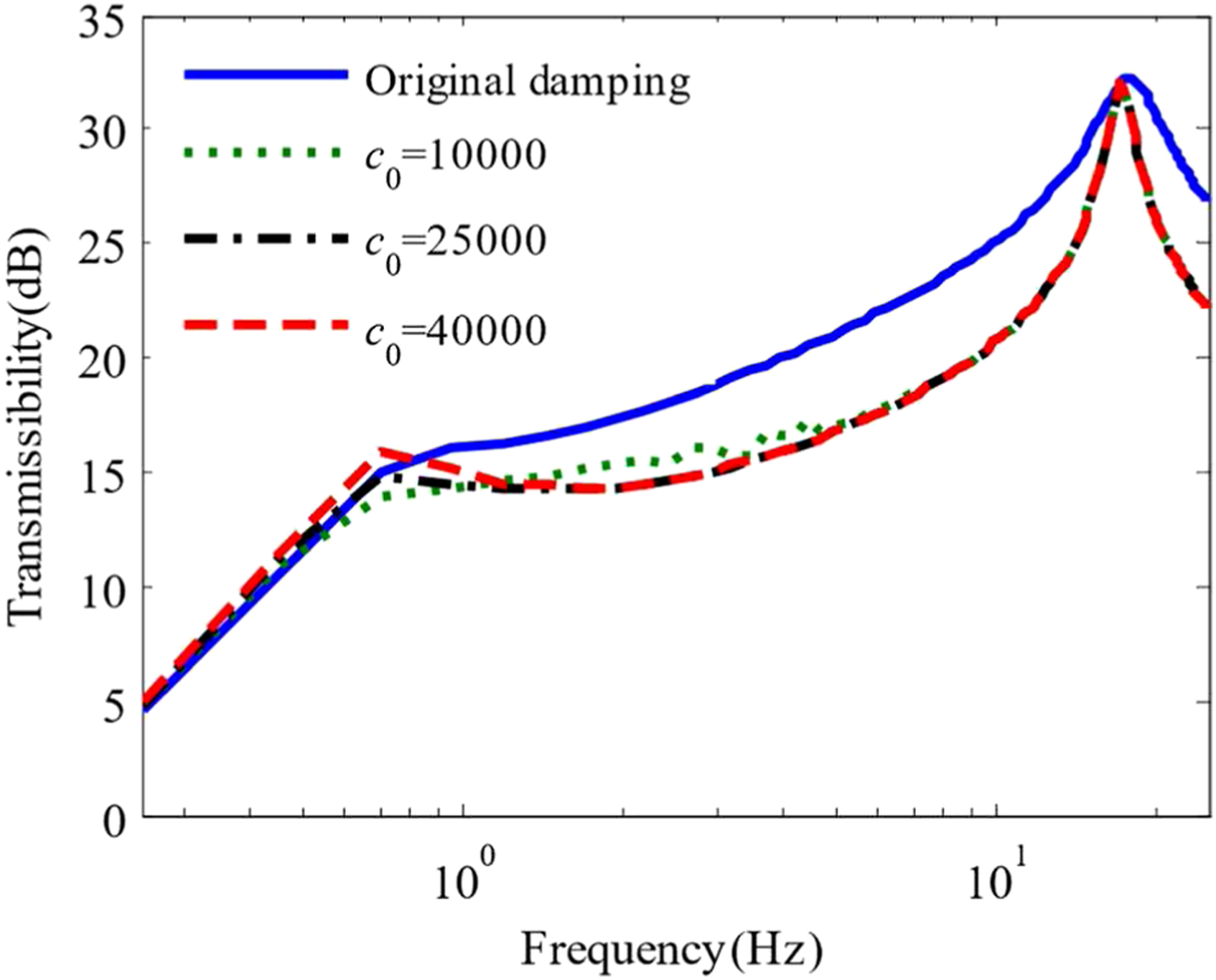
It can be seen that the improved control strategy has an excellent vibration reduction effect in the high frequency range. The effect of vibration attenuation is better than that of the RS control strategy. When the value of c0 is larger, the effect of the control strategy is worse in the low frequency range (<1 Hz); when the value of c0 is smaller, the effect of the control strategy is worse in the range of approximately 1–6 Hz. In general, the value of c0 is 25,000 Ns/m. The improved RS control strategy is simply called “RS-I” in this paper.
Rakheja-Sankar-II control strategy
Another control strategy is designed in this paper. The SH control strategy has an excellent vibration reduction effect in the low frequency band, while the RS-I has an excellent vibration reduction effect in the high frequency band, therefore, a hybrid control strategy is generated by combining the advantages of the two control strategies. The expression of the SH control strategy is
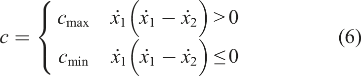
Figure 5 shows the acceleration transmission characteristics of the SH and RS-I control. Analysis of acceleration transfer characteristics.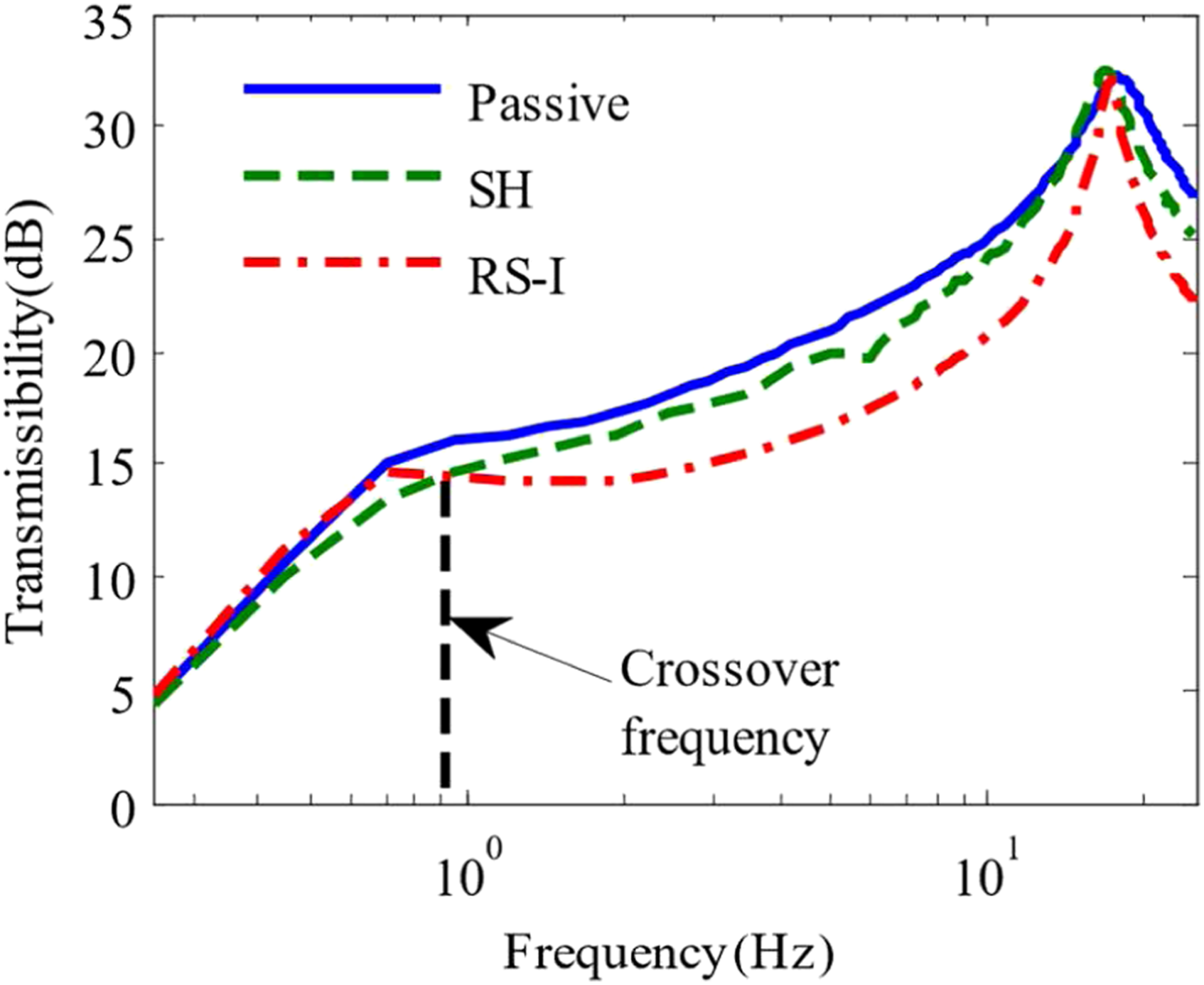
It can be seen from Figure 5, there is a crossover frequency between the SH and RS-I. When the excitation frequency is less than this, the SH control strategy is adopted. Otherwise, the RS-I is adopted. In this way, the best control effect can be achieved. Now, the main task is to find the method for how to switch the frequency.
In this paper, the relationship between the acceleration and displacement of the car body is used to switch the frequency. The sinusoidal signal is applied to the model as the input excitation, there is a special relationship between acceleration and displacement about the amplitudes, and simultaneously, their phase difference is 180°.
Assuming f0 is the crossover frequency,
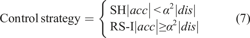
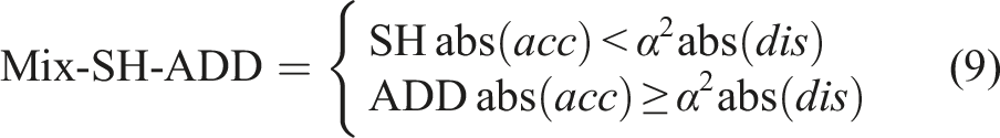
Because of the phase relationship between acceleration and displacement, it is more accurate to use the acceleration and displacement to determine the conversion relationship of the control strategy. Meanwhile, the superiority of this switching method is verified. Assuming the excitation frequency is 0.5 Hz, when abs (acc) < α2 abs (dis), it outputs 1, and then the SH control strategy is executed. Otherwise, the RS-I control strategy is executed. This method is called “switch-II” proposed in this paper. The switch method proposed by Savaresi is named “switch-I” in this paper.
27
The two methods are compared in Figure 6. Comparison of two switching modes.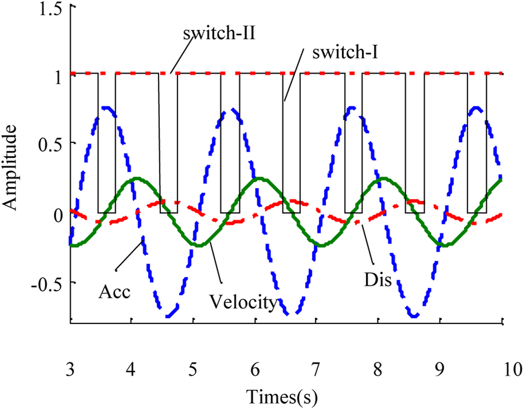
The SH control strategy is not applied for approximately 30% of the time in a period when “switch-I” is used. However, the “switch-II” method is executed at all times, as shown in Figure 6. The control strategy displayed by Expression (7) is called “RS-II,” which is an extension of the RS-I. Obviously as known from Figure 5, f0 is 0.91 Hz. Therefore, the exact value of α is obtained. The acceleration transfer characteristics of the RS-II versus others are obtained, as shown in Figure 7. Comparison of acceleration transfer characteristics of various control strategies.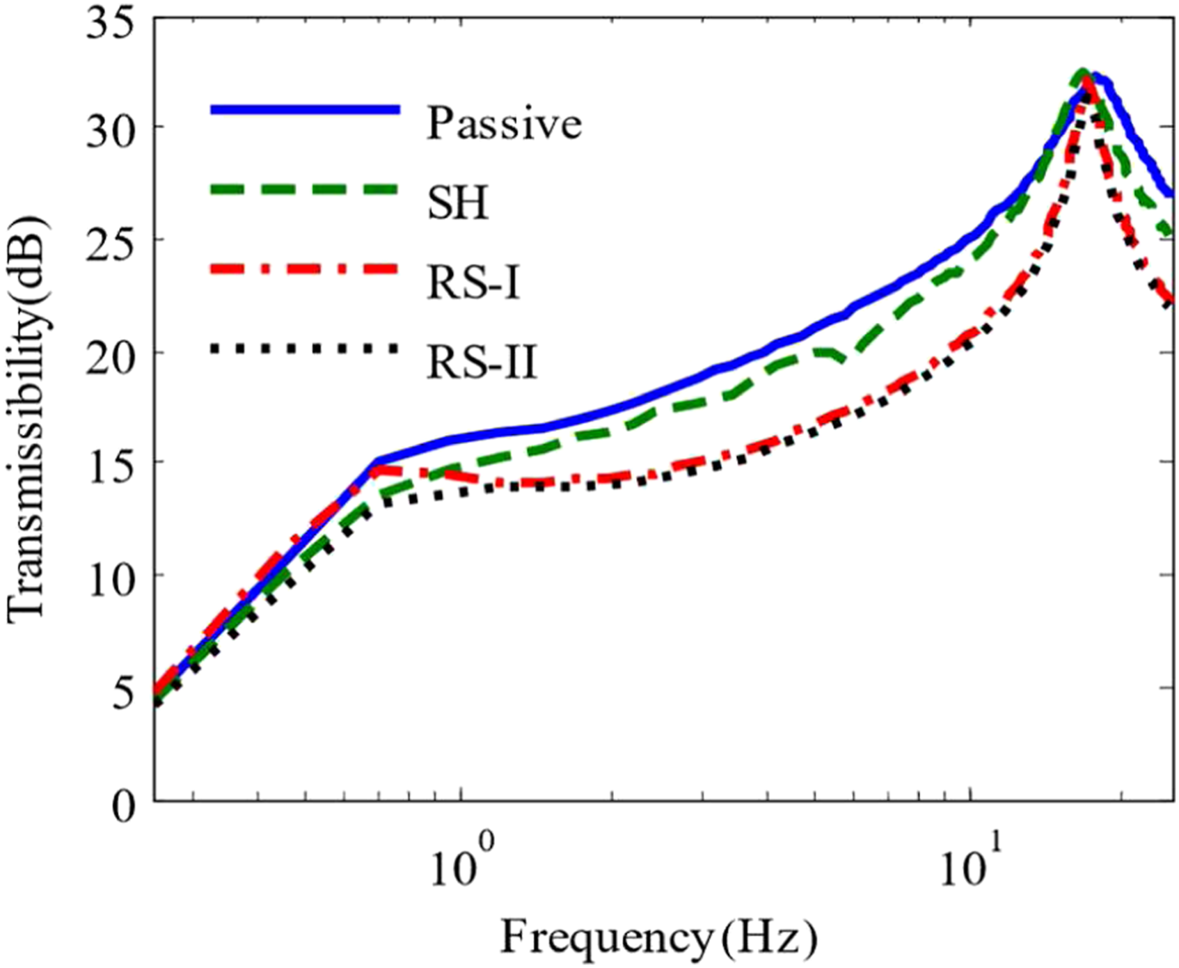
It can be seen in Figure 7 that the RS-II combines the advantages of SH and RS-I and shows superior vibration attenuation performance in all frequency bands.
Because the RS-II has the advantage of the SH in the low frequency range, it should have a better vibration reduction effect than the RS-I.
Simulation analysis of semi-active control strategies
Simulation analysis under sinusoidal excitation
In this section, the attenuation performance of various semi-active control strategies is compared by using sinusoidal excitation and random excitation. The expression of the ADD control strategy is as follows
Therefore, the Mix-SH-ADD is obtained, and the control strategy is as follows
According to Figure 8, the control effects of RS-II and Mix-SH-ADD are the best than others in the whole frequency domain. In particular, the RS-II is better than the Mix-SH-ADD at approximately 1 Hz. Therefore, the vibration attenuation performance of the car body is increased after applying the new control strategy proposed in this paper to the model. Comparison of acceleration transfer characteristics of various control strategies.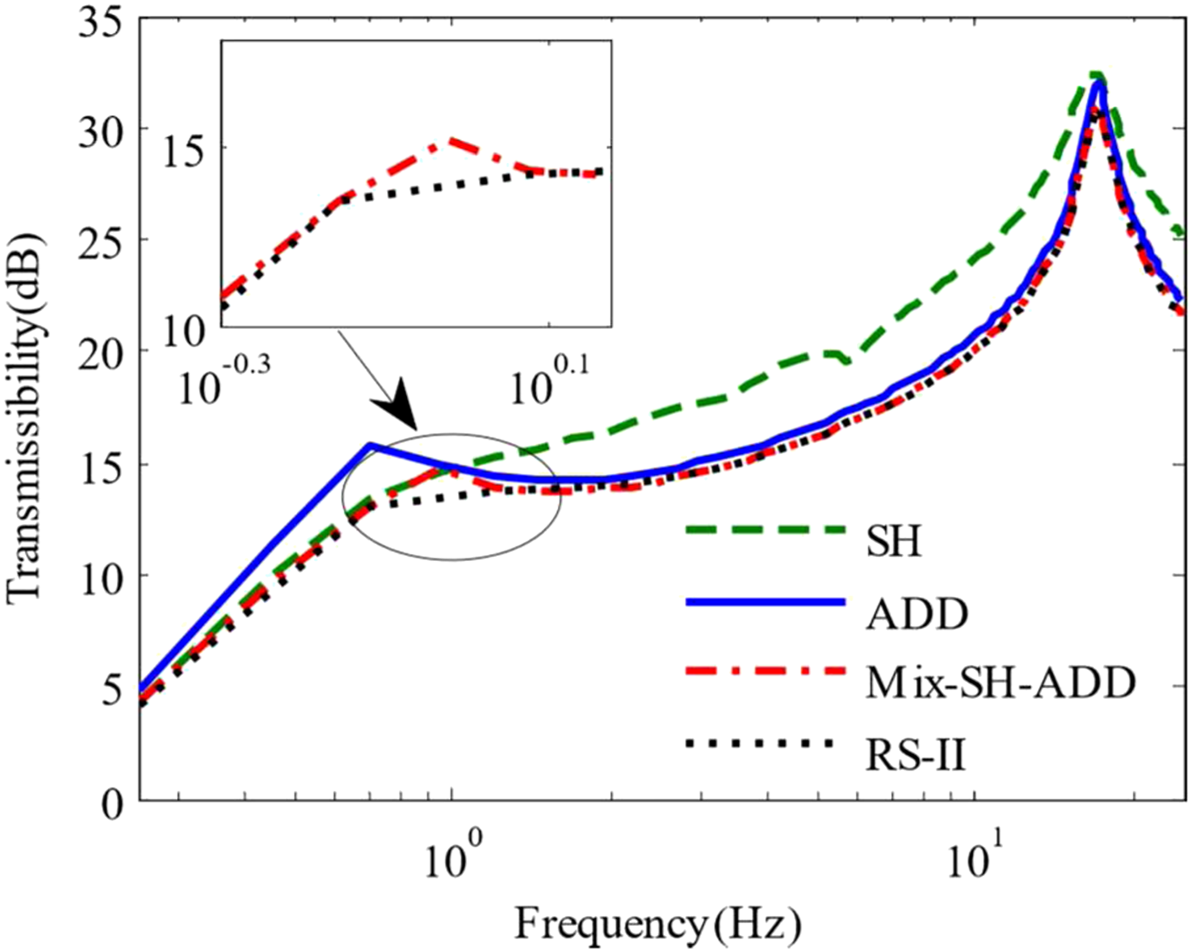
The model with various control strategies is simulated in the time domain with single frequency sinusoidal excitation. The simulation results at a 1 Hz excitation frequency are compared in Figure 9. It is worth noting that each figure only shows the data curves in a certain time period in order to make the picture look clearly in this paper. Acceleration curves of several control strategies under single frequency sinusoidal excitation.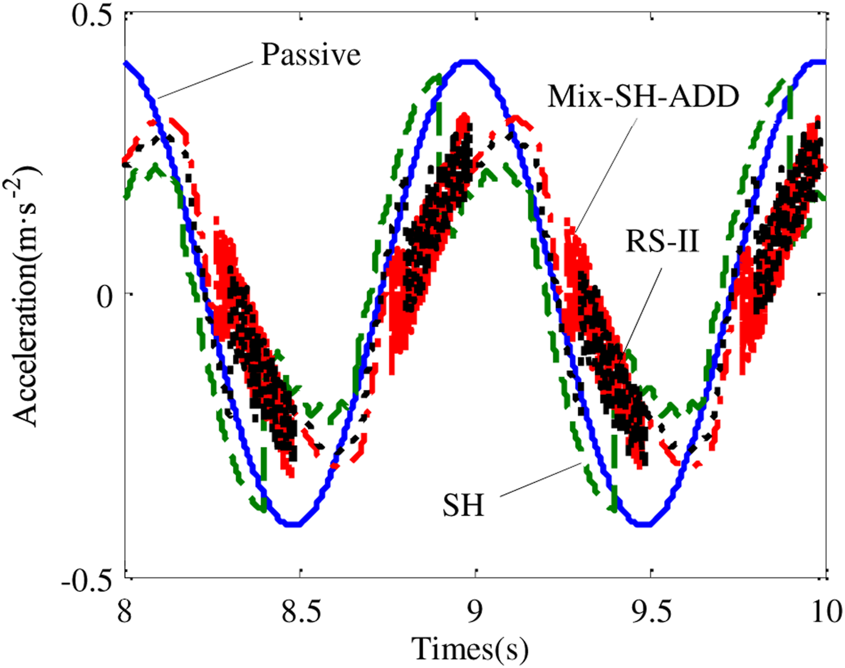
The control strategies introduced in this paper are compared and analyzed by using the simulation conditions mentioned in the Design of control strategies section. Their transfer characteristic curves are shown in Figure 8.
Simulation analysis under random excitation
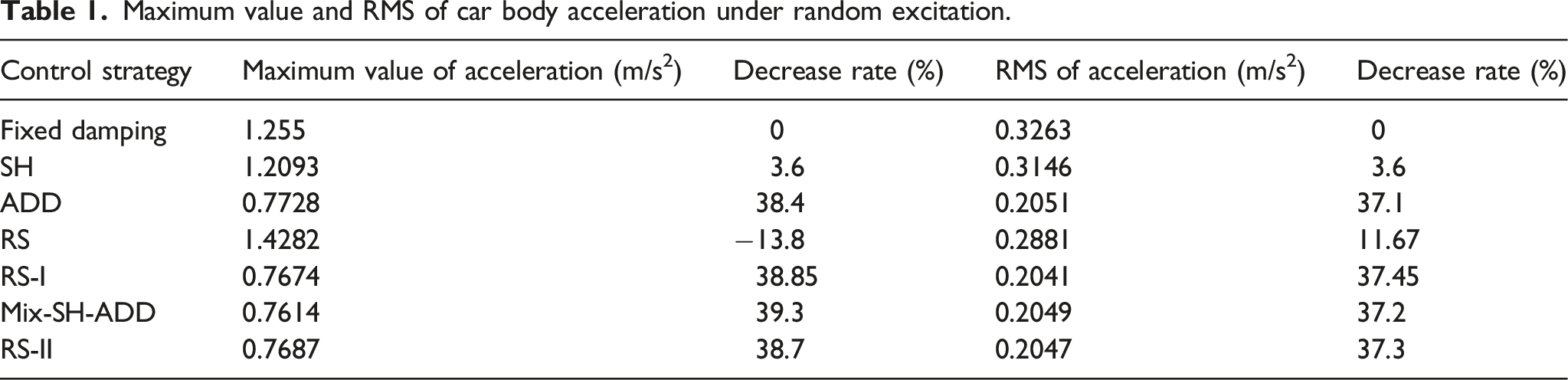
Maximum value and RMS of car body acceleration under random excitation.
The frequency domain analysis of various control strategies under random excitation is shown in Figure 10. Acceleration power spectral density of various control strategies under random excitation.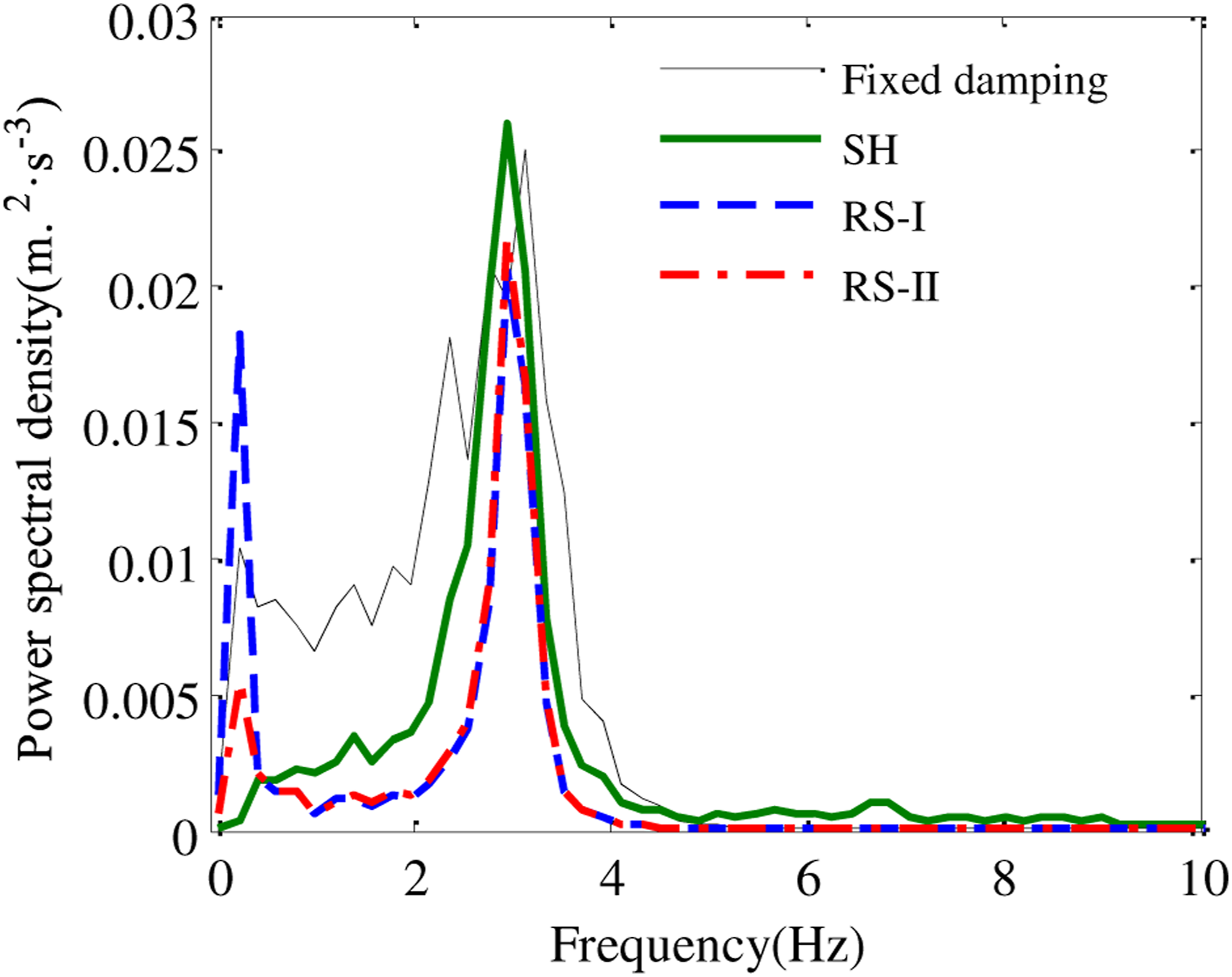
It can be found from Figure 10 that the SH has a lower vibration energy at low frequency and the RS-I has a lower vibration energy at high frequency compared with fixed damping. However, the vibration energy of the RS-II is lower than that of fixed damping across the whole frequency range.
Simulation of the whole vehicle model
Construction of simulation model
In the A quarter vehicle model considering node stiffness section, a quarter vehicle model is established to analyze the control strategies.
Now, it is the objective to assess whether these control strategies are applicable to a full-scale railway vehicle. To this aim, the model of a certain type of high-speed train is established with UM dynamics simulation software. The whole railway vehicle model mainly consists of one car body, two bogies, four wheelsets, and eight axle boxes, which has 58 degrees of freedoms (DOFs).
In order to apply semi-active control strategies to the model, it is necessary to import the vehicle model built in UM into MATLAB/Simulink in the form of an S-function to build a co-simulation model, as shown in Figure 11. Then, vehicle dynamics simulations are carried out where the secondary lateral dampers are driven semiactively. High-speed train co-simulation model.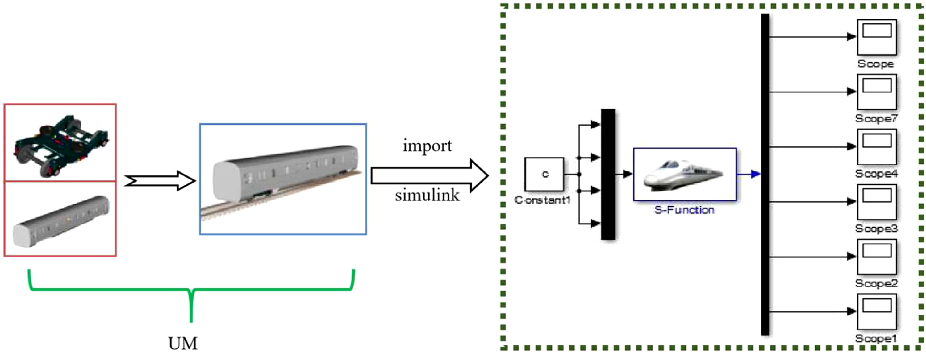
Track irregularity
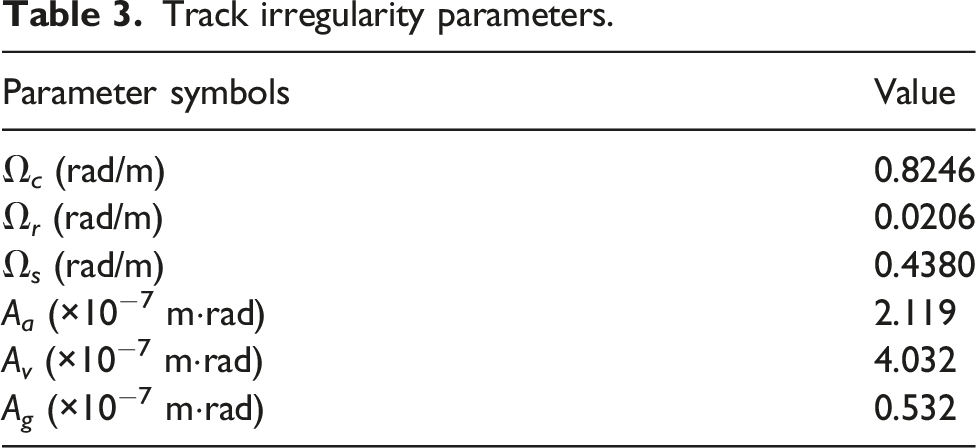
In this paper, the low-disturbance track spectrum of Germany is used as the track irregularity for the semi-active simulation. The low-disturbance track spectrum of Germany is calculated by using the power spectral density (PSD) functions as follows:
32
Alignment irregularity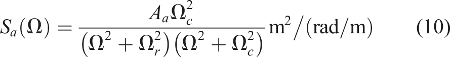
Vertical irregularity: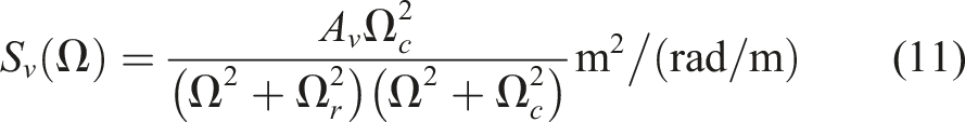
Cross-level irregularity: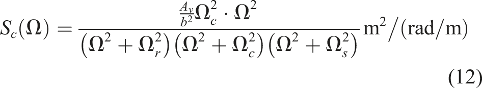
Gauge irregularity: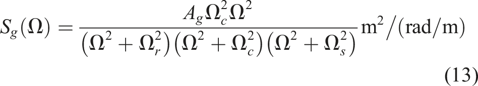
Track irregularity parameters.
Then, the generated track irregularity data are imported into the whole vehicle model for the next simulation.
Ride comfort analysis
A straight track line is used to complete the dynamic simulation of semi-active control. The LMA wheel profile and CN60 rail profile are used for the vehicle model in this paper. Kalker’s simplified creep theory is used to calculate the wheel rail creep force in the vehicle model. Firstly, the ride comfort of the vehicle model is analyzed by applying various control strategies to the secondary lateral dampers. The running speed is set to 300 km/h, which is the normal operating speed of trains.
Generally, the acceleration of the car body can be used to evaluate the ride comfort of trains. However, in order to evaluate the ride comfort more accurately, not only the acceleration but also the influence of acceleration frequency on ride comfort should be considered. To study the influence of semi-active control strategies on ride comfort, the Sperling index, which is commonly used worldwide, is adopted and calculated according to the Standard of China Railway (GB/T 5599-2019). The expression of Sperling index W is as follows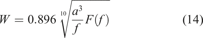
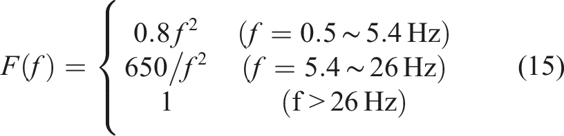
The peak and RMS values of acceleration of different control strategies are given, as shown in Figure 12(a) and Figure 12(b). The Sperling indexes are calculated according to Formula (14) and (15), which are shown in Figure 12(c). Ride comfort analysis under various strategies. (a) The peak values of acceleration under different control strategies. (b) The RMS values of acceleration under different control strategies. (c) The Sperling indexes of different control strategies.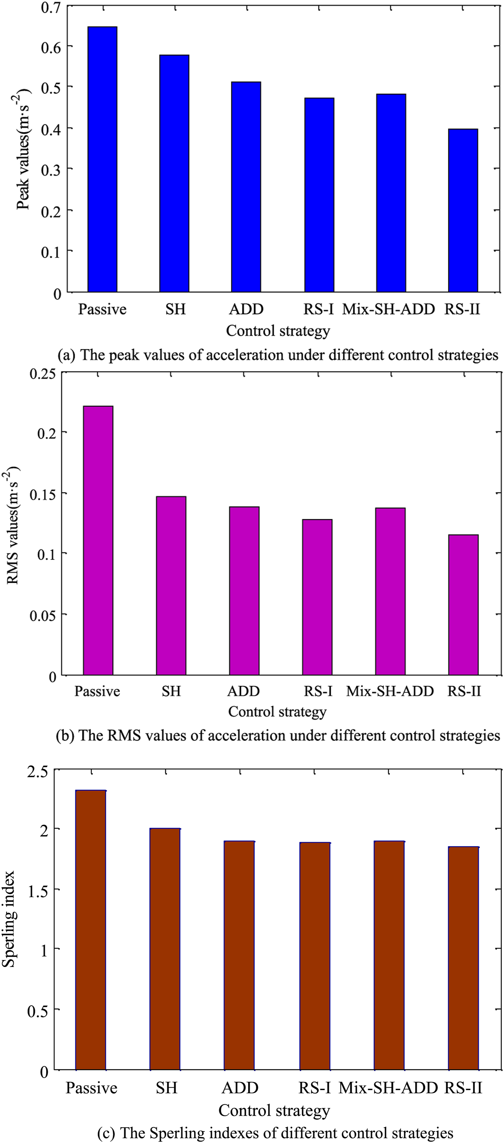
According to Figure 12(a), the peak values of the lateral acceleration of the vehicle body using the SH, ADD, RS-I, Mix-SH-ADD, and RS-II are reduced by 10.58%, 20.81%, 27.01%, 25.62%, and 38.39%, respectively, compared with the passive control. The RMS values of acceleration of the vehicle body decrease by 33.82%, 37.4%, 42.16%, 37.5%, and 47.87%, compared with the passive control, respectively, as shown in Figure 12(b). Finally, the Sperling index decreases by 13.85%, 18.16%, 18.63%, 18.59%, and 20.31%, respectively, as shown in Figure 12(c). In general, the RS-II has the best control effect in restraining the vibration of the car body among these control methods, followed by the RS-I and Mix-SH-ADD. Therefore, the RS-I and RS-II control methods proposed in this paper can reduce the vibration of the car body, and the RS-II is better than RS-I.
Running safety analysis
The purpose of this section is to analyze the influence of control strategies on train running safety. There are some indices that are capable of reflecting the train such as the derailment coefficient, wheelset force and vertical contact force. The lateral interaction force between the wheel and rail against the vertical interaction force is defined as the derailment coefficient. The influence of semi-active control strategies on wheel rail wear is also considered and computed. The wear power P is selected as the evaluation index. The formula is shown as
where, the F α , F β , and Mγ are the longitudinal creep force, lateral creep force (N), and spin moment (Nm), respectively, V is the wheel rolling speed (m/s), and α, β, and γ are the longitudinal creep rate, lateral creep rate, and spin creep (m−1) rate, respectively.
The time domain curves of running safety indexes are obtained under passive control in Figure 13. Similarly, the time domain curves of running safety under other control strategies are obtained. The peak values and RMS values of these indexes are obtained by calculation and comparison, as shown in Table 4. In this paper, “Passive” means the result of a fixed damping coefficient. Evaluation indexes on the running safety of the railway vehicle under 300 km/h. (a) Derailment coefficient. (b) Wheelset force. (c) Vertical contact force. (d) Wear power. Comparison results of dynamic indices under several control strategies.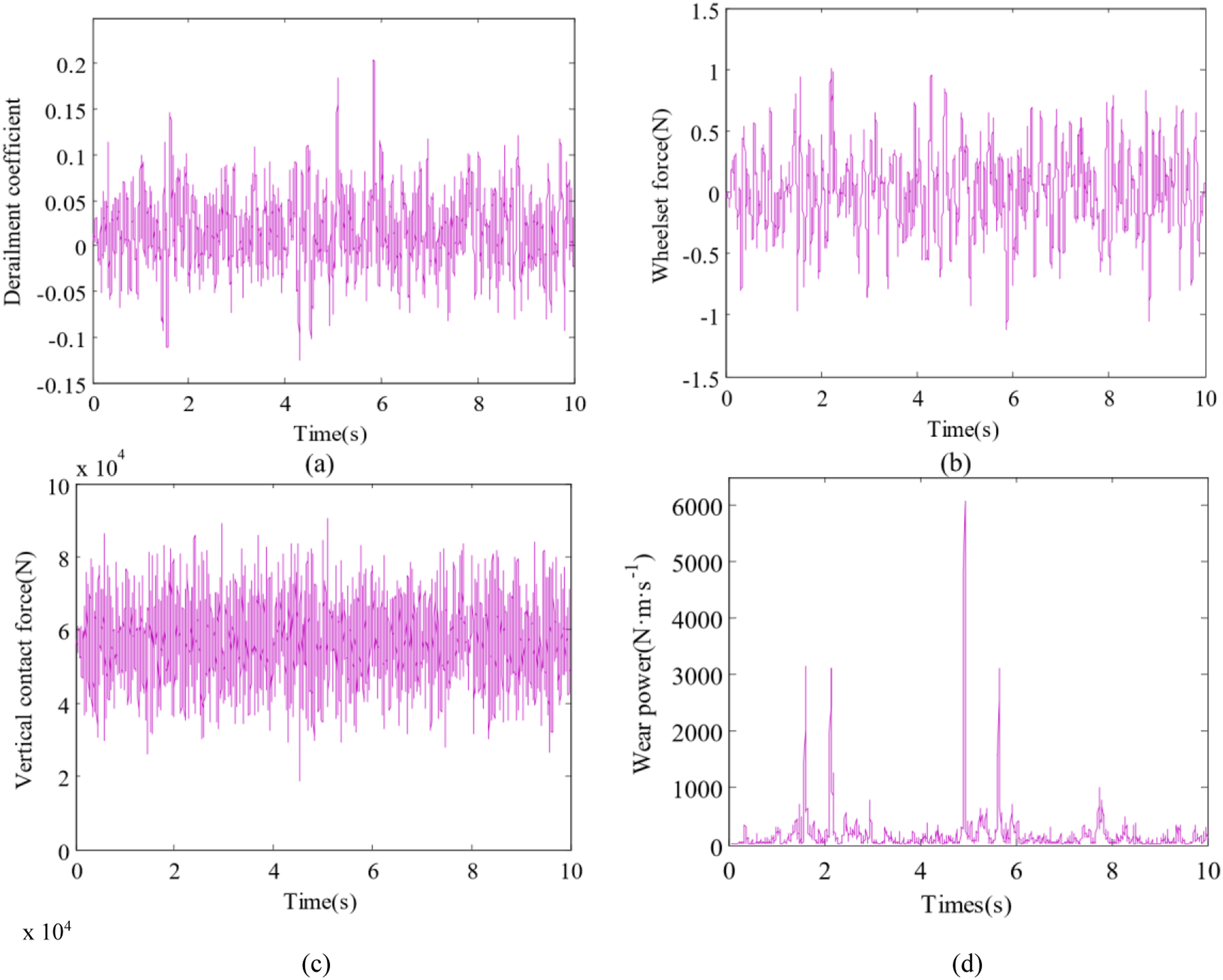
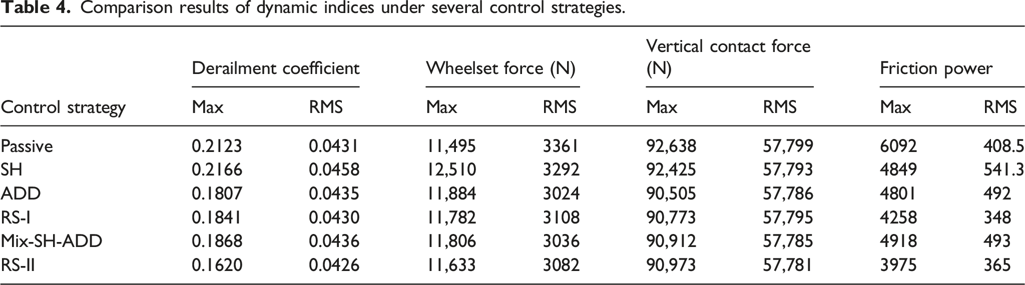
Table 4 shows that the proposed control strategies RS-I and RS-II have little influence on the running safety of trains. All indexes are within the specified standard range. They can ensure the safety of the train while improving ride comfort. It is worth noting that they can reduce wear.
Hunting stability analysis
Analyzing the critical speed is a common way of evaluating train hunting stability. In a straight track, the wheelset displacement is measured to determine whether it converges or diverges after impulse excitation. At a certain speed, the amplitude of the wheelset lateral displacement does not increase or decrease, that is, at a constant amplitude steady-state vibration, the speed at this time is the critical speed of the vehicle. If the speed is less than the critical speed, the train will be stable. When the speed is greater than the critical speed, the train will lose stability. The scanning speed method is used in this paper, as shown in Figure 14, which is also called the reducing speed method.
33
According to this method, the critical speeds of the train under different control strategies are calculated and represented by the bar chart in Figure 15. Critical speed calculated by scanning speed method. Critical speed under several control strategies.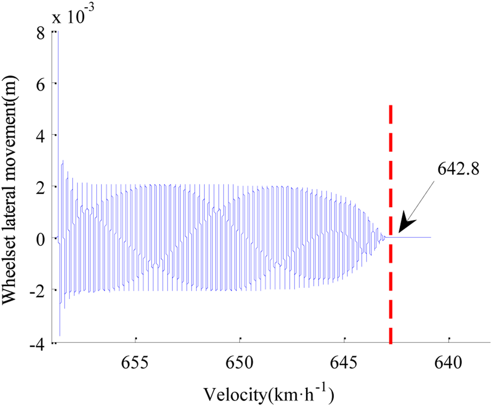
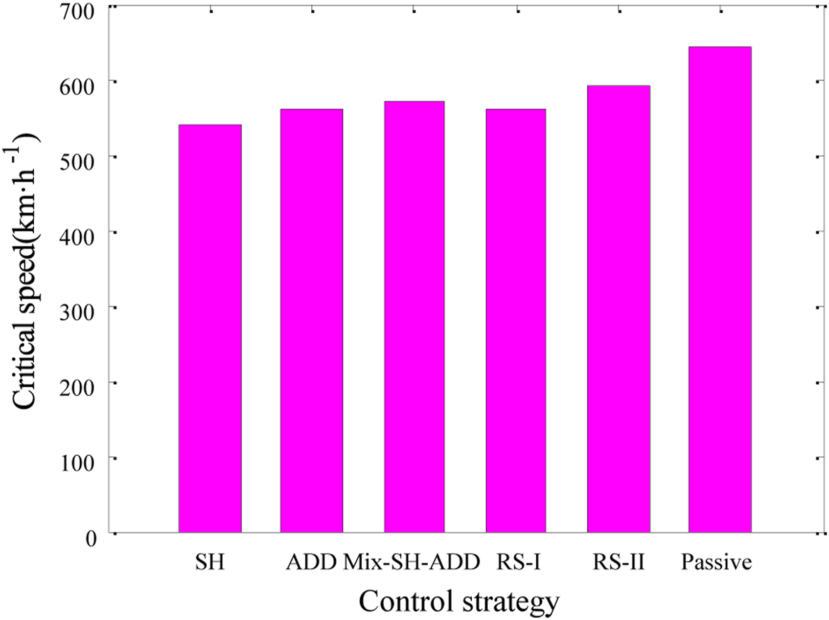
As it can be seen from Figure 15, when the semi-active control strategies are applied to the train, the critical speed is lower than that of the passive control. The critical speed of the SH decreases the most. In addition, the decrease of the critical speed of the RS-II is the least. Among these semi-active control strategies, the RS-II has the best stability.
Although the semi-active control strategy reduces the critical speed, it is still far higher than the real running speed of the train. The semi-active control strategy is still effective and has great practical value.
The RS-I and RS-II proposed in this paper can effectively improve ride comfort. At the same time, they can ensure the running safety and stability of high-speed trains.
Hardware-in-the-loop experiment
HIL systems, which have the advantages of low cost and high security, are widely used to verify and test a product before application. A hardware-in-the-loop (HIL) system that mainly includes one upper computer, one lower computer, one force sensor, one MR damper, and one electric cylinder is built for the semi-active control experiment to verify the semi-active control strategies in this paper. The schematic and physical configuration of the HIL system are shown in Figure 16. The schematic and physical configuration of the HIL system. (a) The schematic diagram of the HIL system. (b) The physical configuration of the HIL.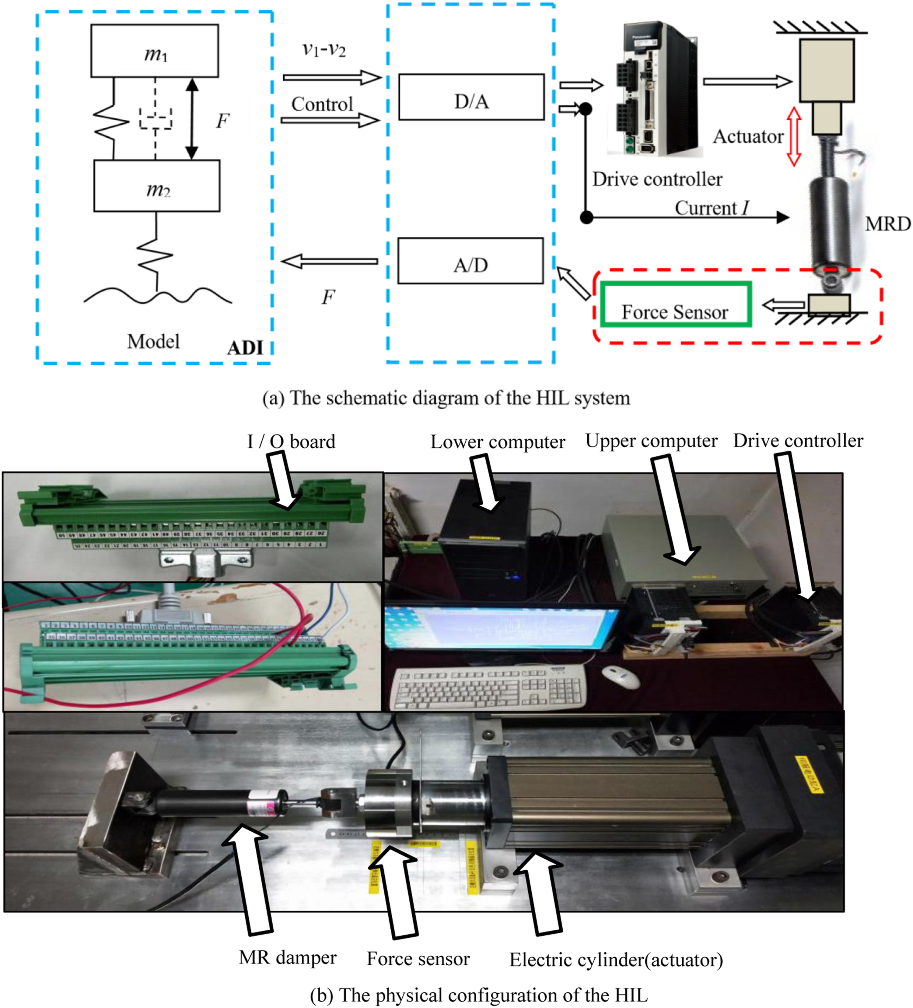
In the HIL system, one side of the MR damper is fixed, and the other side is actuated by the actuator, which moves according to the relative velocity from the car body to the bogie in the model. The force sensor collects the force generated by the MR damper and converts it into an analog voltage signal to be fed back to the model. The real MR damper embedded in the system is closer to the real operating environment than the theoretical simulation. In the experiment, the RTX real-time simulation system from the ADI company is adopted to compile the model to complete the connection with the external hardware. The acceleration data of the car body under the action of the real MR damper are obtained by the HIL experiment.
Under the single harmonic excitation with a frequency of 1 Hz and an amplitude of 5 mm, the comparison curves of car body accelerations are obtained, as shown in Figure 17(a). Figure 17(b) shows the experimental results of car body accelerations when a composite harmonic excitation including three frequency components of 0.5 Hz, 1 Hz, and 2 Hz is applied. To make the experiment more comprehensive, the random excitation is used for the test to verify the semi-active control strategies. The acceleration curves obtained from the experiment are shown in Figure 17(c). Test curves under different working conditions. (a) Acceleration experiment curves under sinusoidal excitation. (b) Acceleration curves under the excitation with multiple frequency components. (c) Acceleration curves of several control strategies under random excitation.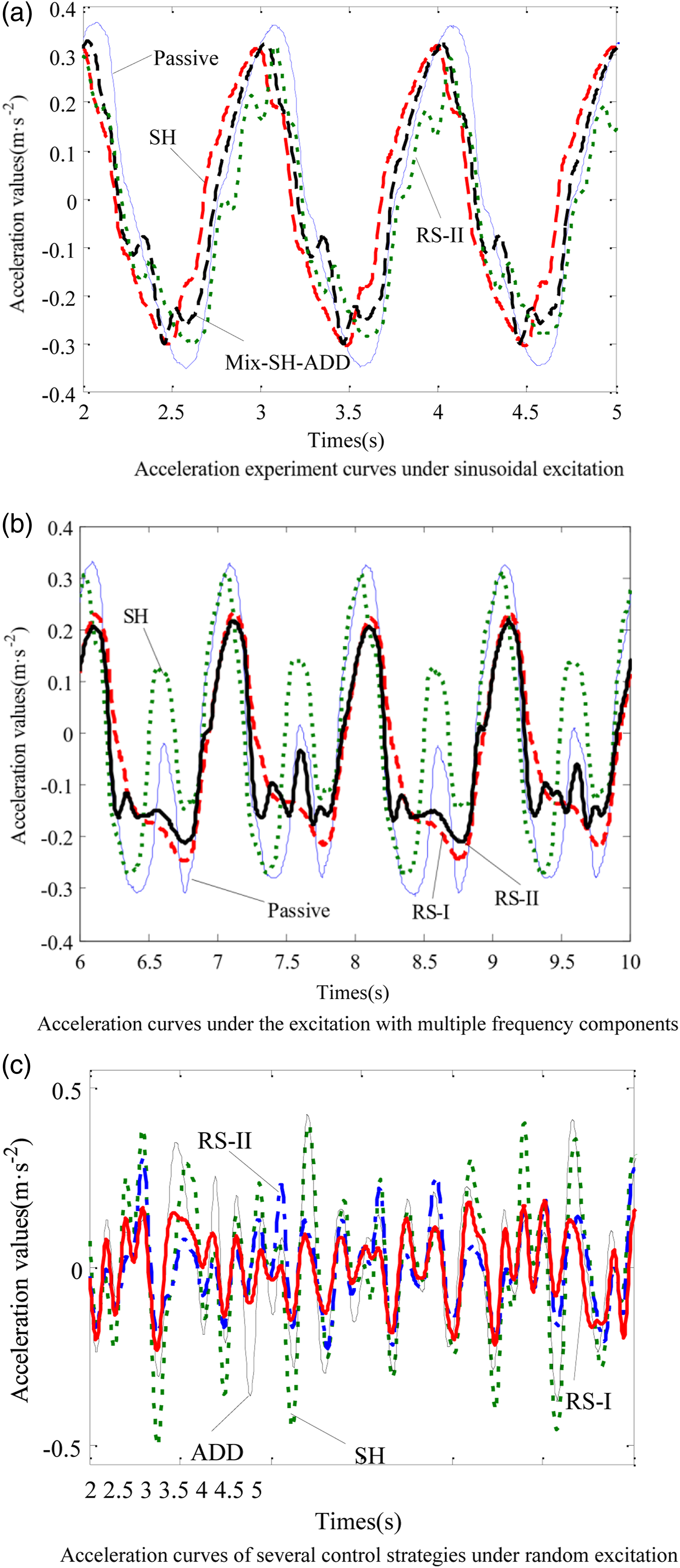
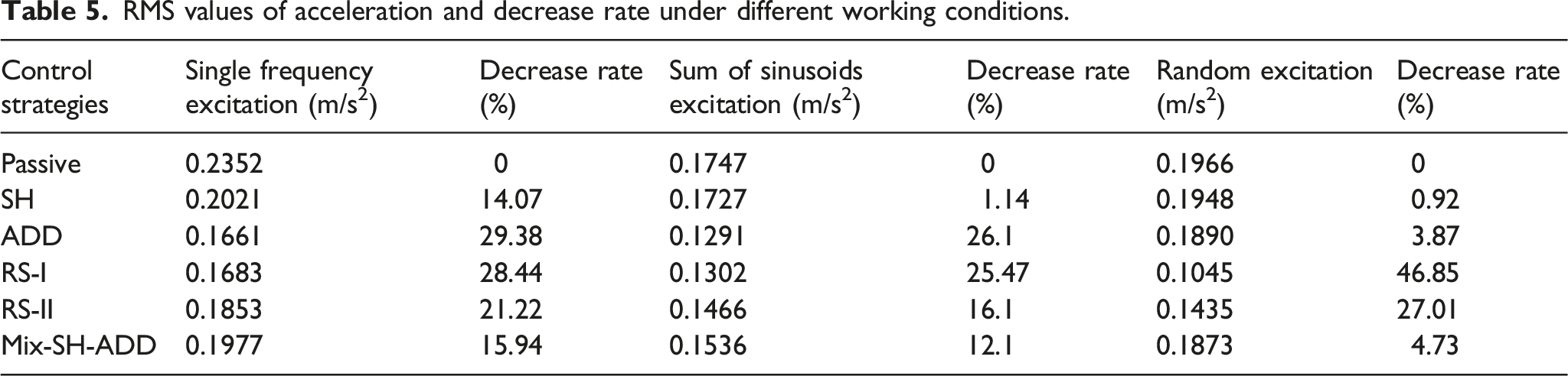
RMS values of acceleration and decrease rate under different working conditions.
Conclusion
The conclusions of this paper are as follows: (1) The two control strategies, RS-I and RS-II, are designed in this paper and compared with other control methods. Simulation analysis with a quarter railway vehicle model is carried out. The results show that the two control strategies can reduce the acceleration of the vehicle body and have a good control effect. (2) The UM-MATLAB simulation results show that the two control strategies can not only improve ride comfort but also ensure the safety of the train. The control effect takes into account the dynamic performance of the train. Furthermore, RS-II has the best stability among all semi-active control strategies in this paper. (3) In this paper, the hardware-in-the-loop method is used to analyze the semi-active control strategy. The results show that the experimental results are consistent with the theoretical results, which proves that the control strategy proposed in this paper is practical. (4) It is very interesting to study semi-active control strategies. This paper is just the beginning. Most importantly, the research results should be applied to engineering practice. In the future, a controller with semi-active control algorithms will be developed, and a real full-scale vehicle test will be carried out. Furthermore, the authors not only improve the comfort by using semi-active control strategies but also enhance the safety and stability of high-speed trains. Meanwhile, the continuous control strategy will also be studied.
Footnotes
Acknowledgements
The author(s) thank the State Key Laboratory of Mechanical Behaviour in Traffic Engineering Structure and System Safety for providing equipments to the experiment. The work is supported by the National Natural Science Foundation of China (Nos. 11790282, 12172235, 12072208 and 52072249), the Opening Foundation of State Key Laboratory of Shijiazhuang Tiedao University (ZZ2021-13), and the Postgraduate Foundation of Hebei Province (CXZZBS2021112).
Declaration of conflicting interests
The author(s) declared no potential conflicts of interest with respect to the research, authorship, and/or publication of this article.
Funding
The author(s) received no financial support for the research, authorship, and/or publication of this article.