
Abstract
It is known that good curving performance and stability often have conflicting requirements given a passive yaw stiffness of the wheelset. Using an active steering system, however, has the potential to realize improved curving performance with a satisfactory running stability. Relatively simple active control solutions of yaw relaxation and yaw compensation are illustrated and compared in this paper. In both control solutions, only low-cost electromechanical actuators and load cells are adopted for low-frequency actuations. Associated with a prototype of the two-axle vehicle, the dynamic performances of yaw relaxation and yaw compensation controls for different yaw stiffness configurations are simulated. The homogenous simulation results demonstrate excellent dynamic performance in curve negotiation and stability with the active steering strategies adopted.
Introduction
It is well known that a solid-axle wheelset has good passive steering capacity due to its conicity and its integrity of wheels and axle. With a low yaw stiffness, the solid-axle wheelset has a relatively good curving performance; however, the hunting motion (kinematic instability) can result due to the wheel tread conicity. In contrast, using a high yaw stiffness can resist hunting motion but result in large wear and wheel/rail force during curve negotiation, since the steering of the wheelset is strongly constrained. As curve negotiation and hunting motion take places at different time scale, curve negotiation and stability issues can be solved separately in the frequency domain without a compromise of the yaw stiffness value. In this sense, an active control could be a suitable approach to obtain satisfactory curving performance and stability simultaneously.1–4
To improve the dynamic performance of the wheelset, many active steering approaches have been discussed and investigated.5–13 The measurement of the control signal is a very important issue for the feasibility of the control system. Naturally, it is preferable to utilize the vehicle-based quantities as the control signals for the actuation system, since the measuring systems can be robust and cost-effective and the measured signals are more reliable. In fact, the physical quantities of the wheel/rail interface are difficult to measure, such as the wheel/rail lateral displacement, the wheelset attack angle, etc., which possibly involve high costs and unsatisfactory reliabilities.
In various studies,5,9,11,12 active strategies with the concept of ‘zero suspension torque in yaw direction’ are discussed and illustrated. This simple approach in Shen and Goodall 5 takes the advantage of the natural steering effect of the wheelset to negotiate the curve with an almost pure rolling performance. The low-frequency linear actuator can properly control the steady-state curving behaviour by releasing the constraints of the wheelset in the yaw direction. This actuator only needs to provide very low frequency steering forces below 0.5 Hz, whereas the instability of the wheelset can be resisted at higher frequencies by a relatively large yaw stiffness. In this actuation system, the electromechanical actuator can be selected for this application due to its low cost and relatively high reliability.
For the railway industry, a relatively high yaw stiffness for the wheelset is required not only to resist the hunting motion but also to ensure the integrity of the vehicle in the longitudinal direction, especially during the traction and braking. ‘Yaw relaxation control’ 5 is based on the serial connection between the actuator and the principal longitudinal spring, which provides the main yaw stiffness at high frequencies. In this configuration, a low value of other contributions to the yaw stiffness, such as the shearing stiffness of the vertical coil spring, is required to achieve the effective curving. However, the yaw relaxation control cannot function effectively in the vehicle with a high yaw stiffness, since the curving behaviour is determined by the high yaw stiffness. To realize the radial curving performance for a high-yaw-stiffness vehicle, the control solution for the configuration of the actuator and longitudinal spring in parallel needs to be investigated. Under this framework, a control method named ‘yaw compensation’ is developed based on the ‘yaw relaxation’ control.
Active steering solutions via electromechanical actuators
Yaw relaxation control – actuator and spring in series
The yaw relaxation approach utilizes the natural steering effect of a wheelset with a low yaw stiffness to negotiate a curve by releasing the internal steady-state loads of the electromechanical actuators. Therefore, the measurement required by the control system is only the actuation force of the electromechanical actuator, which can be measured readily by a load cell. Since the active steering system is designed to function in the yaw direction only, traction and braking components of the actuator loads need to be eliminated from the feedback signal. During a traction or braking process, two equal forces in the longitudinal direction can occur in both actuators’ load cells of the same wheelset. The needed feedback signal, the actuator force, should be calculated by subtracting the average of the measured loads from both load cells. This principle also applies to the yaw compensation control. Figure 1 demonstrates the electromechanical actuator model used in this application. Inside this actuator model, the PID controller is used to control the displacement of the screw nut to release the low-frequency internal load by a current control. Since the actuation process only takes place at very low frequencies (far below 1 Hz), the controller is designed to have low frequency response features with a high-frequency cut-off effect. In this sense, the high-frequency hunting motion of the wheelset can be prevented by the serial spring. Moreover, the serial spring with a high stiffness has almost no influence on the curve negotiation. It can be seen that the relaxation is a displacement-based control strategy for active steering.
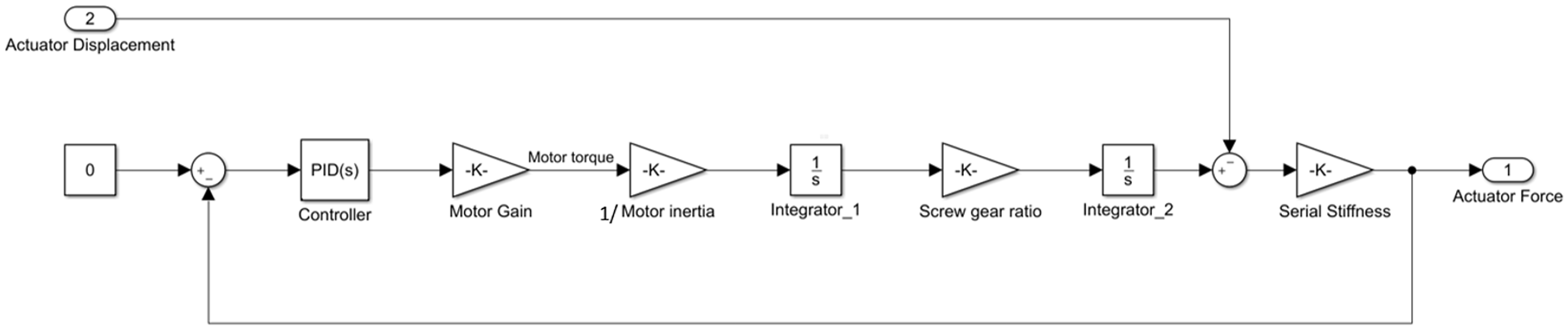
Yaw relaxation control model via electromechanical actuator (per side).
Yaw compensation control – actuator and spring in parallel
As a high yaw stiffness is adopted for the wheelset without active steering, the steering of the wheelset is constrained due to the large yaw stiffness, generating the unwanted longitudinal and lateral creep forces. However, it is feasible to construct a ‘low yaw stiffness’ during the curve negotiation by introducing an active force from the actuator to balance the load generated by the longitudinal spring. By a continuous compensation of the longitudinal spring force, the wheelset is able to steer to the radial position with the ‘constructed’ low yaw stiffness. Meanwhile, the longitudinal spring can still function at high frequencies to resist the hunting motions. Similar to the yaw relaxation control, it is also feasible to employ the electromechanical actuator to provide the low-frequency actuation force. Figure 2 illustrates the electromechanical actuation model for this scenario.
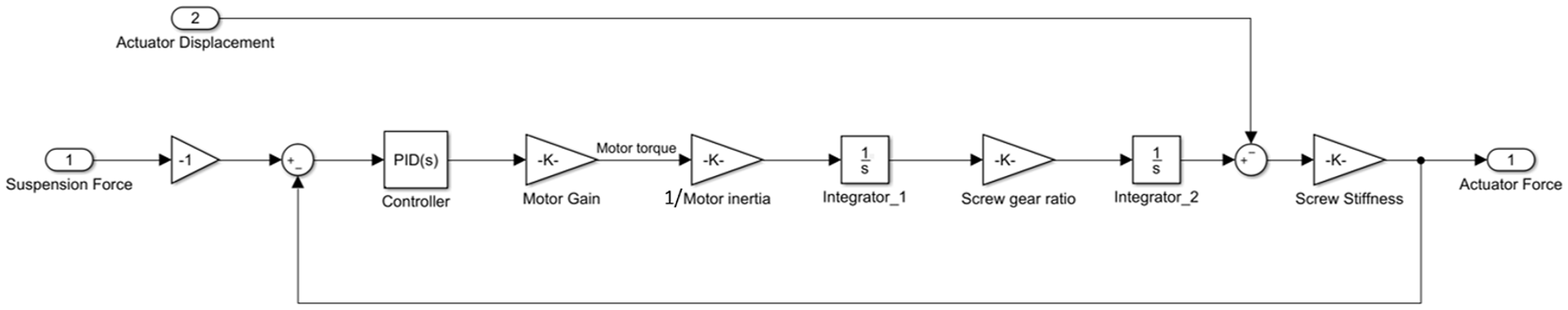
Yaw compensation control model via electromechanical actuator (per side).
In this actuation model, in addition to the load cell inside the actuator for the feedback control, another load cell needs to be installed to measure the internal force of the longitudinal spring. Corresponding to the measured longitudinal spring force, the electromechanical actuator generates the low-frequency actuation load in the opposite direction by the adjustment of the displacement of the screw nut. Similar to yaw relaxation, the longitudinal traction and braking components of the actuator loads should be eliminated from both feedback signal and control signal of the same wheelset. In this scenario, the feedback signal, the load cell measurement of the actuator, should be calculated by subtracting the average of measured loads from both actuators’ load cells. Meanwhile, the control signal, the load measurement from the suspension, should be calculated by subtracting the average of the corresponding measured suspension forces. For the electromechanical actuator, the actuator length also leads to the spring force due to the stiffness of the screw nut, which virtually increase the yaw stiffness at high frequency to resist the hunting motion.
Comparisons of yaw compensation and yaw relaxation
For the steering mechanism, the principle of yaw compensation control is similar to yaw relaxation control in the allowance of the free steady-state movement of the wheelset during the curve negotiation. In yaw relaxation control, the actuator only needs to release its own internal load during the curve negotiation, since the suspension force in the yaw direction has almost no influence on the natural curving behaviour of the wheelset. However, in the yaw compensation control, the actuator is required to counteract the suspension force during the curving process to realize the ‘relaxation’ of the wheelset in the yaw direction. This means that the suspension force is required to be measured and functions as the input signal of the control system. Meanwhile, for both control methods, the passive springs (serial or parallel) of high yaw stiffness function at high frequencies to avoid the hunting motions, which guarantee the stabilities of the wheelsets. In this research, the two simple actuation models (shown in Figures 1 and 2) are used to illustrate that the control characteristics and mechanical properties of electromechanical actuators can be properly utilised to improve dynamic behaviours of the vehicles. A more comprehensive modelling of the actuation system can be carried out in a further development process.
Simulations and analyses
In order to compare the control strategies mentioned above, the Simpack-Simulink co-simulation is utilized here regarding a prototype of a two-axle bogie-less vehicle. In this co-simulation, the multi-body model in Simpack can directly communicate with a control model designed in MATLAB/Simulink in the time domain. For a multi-body vehicle model, its control input is the force/torque by the actuation system, while its output is the measured dynamic signal from the vehicle. In this two-axle vehicle with an axle load of 11 t, only one single stage of suspension is adopted in the suspension system. The wheelset is connected with a sub-frame, on which the suspension component is installed. The relative movement between the wheelset and the sub-frame only takes place in the pitch direction. Figure 3 provides general layouts of running gears regarding the two active control approaches. Several key parameters of the two-axle vehicle are listed in Table 1. This table also includes actuator parameters used in the simulation as a general example. In a real application, the selection of actuator parameters should be based on corresponding mechanical and electrical requirements. As the vehicle is equipped with the active steering technique, a wheel profile with a larger flange clearance can be applied due to the reduced flange contact on the curve. Here the British wheel profile BR-P8 with a flange clearance of 9.3 mm is adopted in this vehicle model.
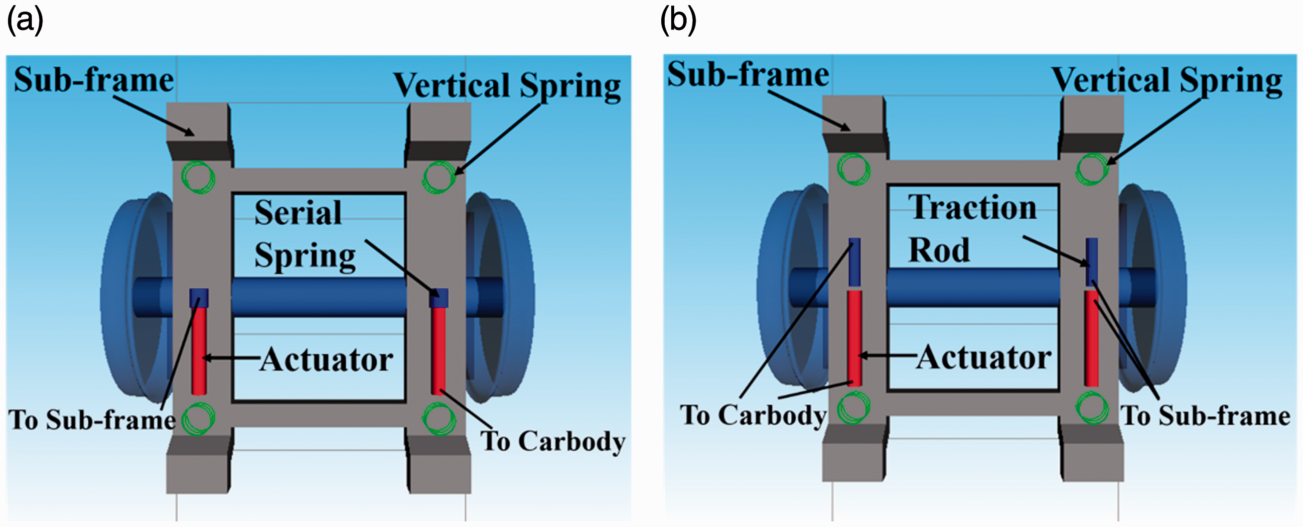
General layouts of running gears for two active steering approaches. (a) Yaw relaxation control; (b) yaw compensation control.
Main parameters of the two-axle vehicle model.
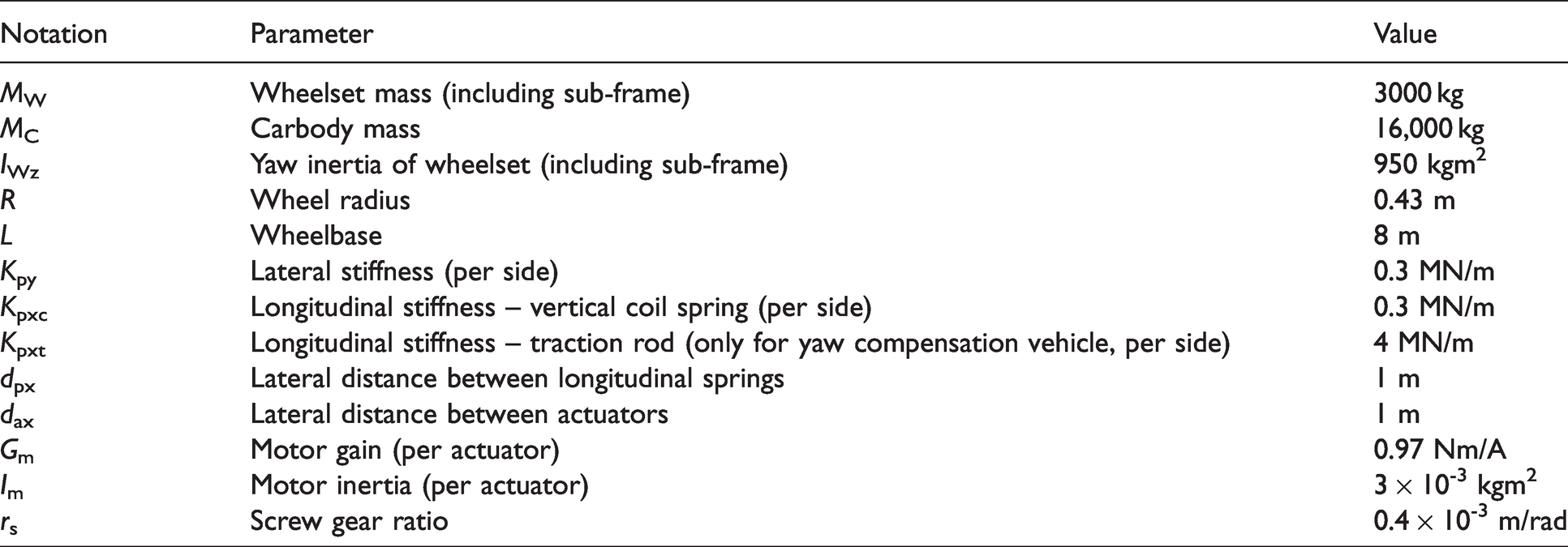
For the yaw relaxation configuration, the shearing stiffness of the vertical coil spring contributes to the yaw stiffness of the wheelset during the curve negotiation with a very small value of 0.15 MNm/rad (per side). The stiffness of the serial spring connected with the actuator is 5 MN/m (per actuator), which functions at high frequencies. For the yaw compensation configuration, besides the shearing stiffness of the vertical coil spring, the traction rod is installed between the carbody and the sub-frame serving as a principal longitudinal spring for the stability purpose, whose stiffness value is 4 MN/m per side. In its actuator, a low value of the stiffness is selected (1 MN/m for each actuator) to avoid a large reaction force in the curve. To clarify the characteristic of the yaw stiffness with the introduction of the active steering system, it is possible to define a quasi-static yaw stiffness for the curve negotiation and a dynamic yaw stiffness for the stability. Table 2 provides the quasi-static and dynamic yaw stiffness for both control approaches, which have the same values. It can be seen the dynamic yaw stiffness are much higher than the quasi-static yaw stiffness.
Quasi-static and dynamic yaw stiffness for different control approaches.
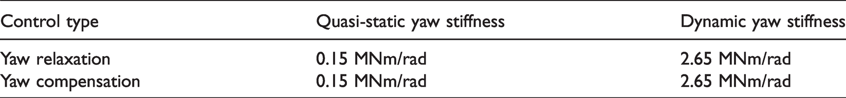
Figure 4 exhibits the frequency responses of the tuned closed loops for both control strategies. It can be noticed that the movement of the actuator mainly concentrates on the very low frequency range, while the response at a high frequency is very small. This represent a ‘low-pass filtering’ effect. It means the actuator can move freely at very low frequencies and keep rigid at high frequencies. This behaviour is beneficial for both curving and stability performances. In fact, only small PID gains are used to achieve this behaviour. The small control gain requires low control efforts and is well-suited to a low-cost controller.
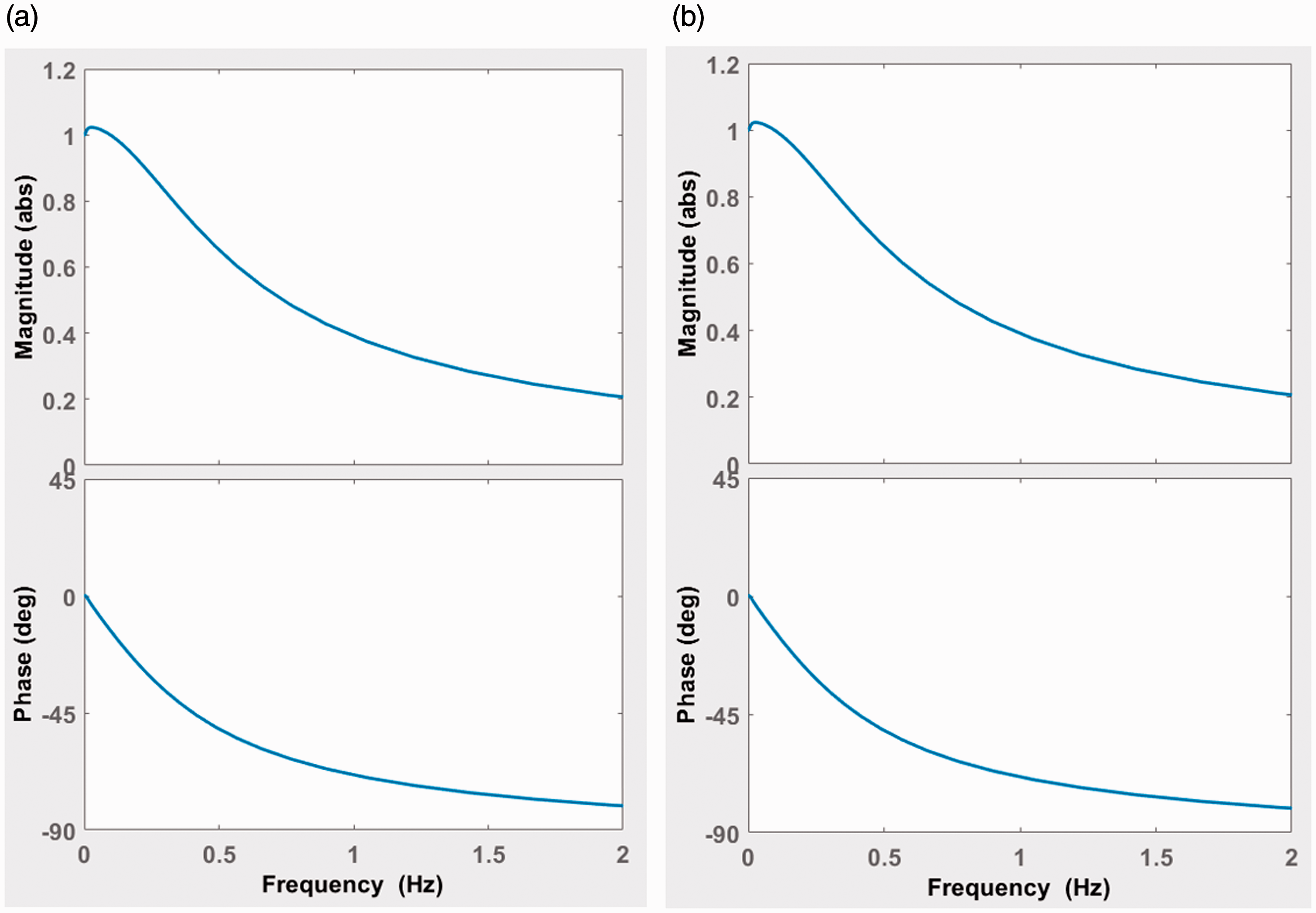
Bode diagrams of tuned control loops for both active approaches. (a) Yaw relaxation approach; (b) yaw compensation approach.
Curve negotiation performance
Here a few track cases are adopted to test the curving performances with the active steering approaches. The track cases include a 250 m radius curve with a cant of 150 mm and a very short transition of 60 m.
Figure 5 shows the dynamic behaviour of the passive two-axle vehicle with a yaw stiffness of 2.65 MNm/rad for the 250 m curve at 72 km/h, corresponding to a cant deficiency condition with an uncompensated lateral acceleration of 0.65 m/s2. It can be seen from Figure 5 that flange contact at the leading wheelset results in very large track forces and wheel/rail wear indices. The attack angle of the leading wheelset is very large because the high yaw stiffness restrains the yaw movement of the wheelset. The understeer of the leading wheelset results in a large lateral creep force. Although the trailing wheelset exhibits a better performance than that of the leading wheelset in the curve, the high yaw stiffness still confines the movements of the trailing wheelset and leads to its oversteering.
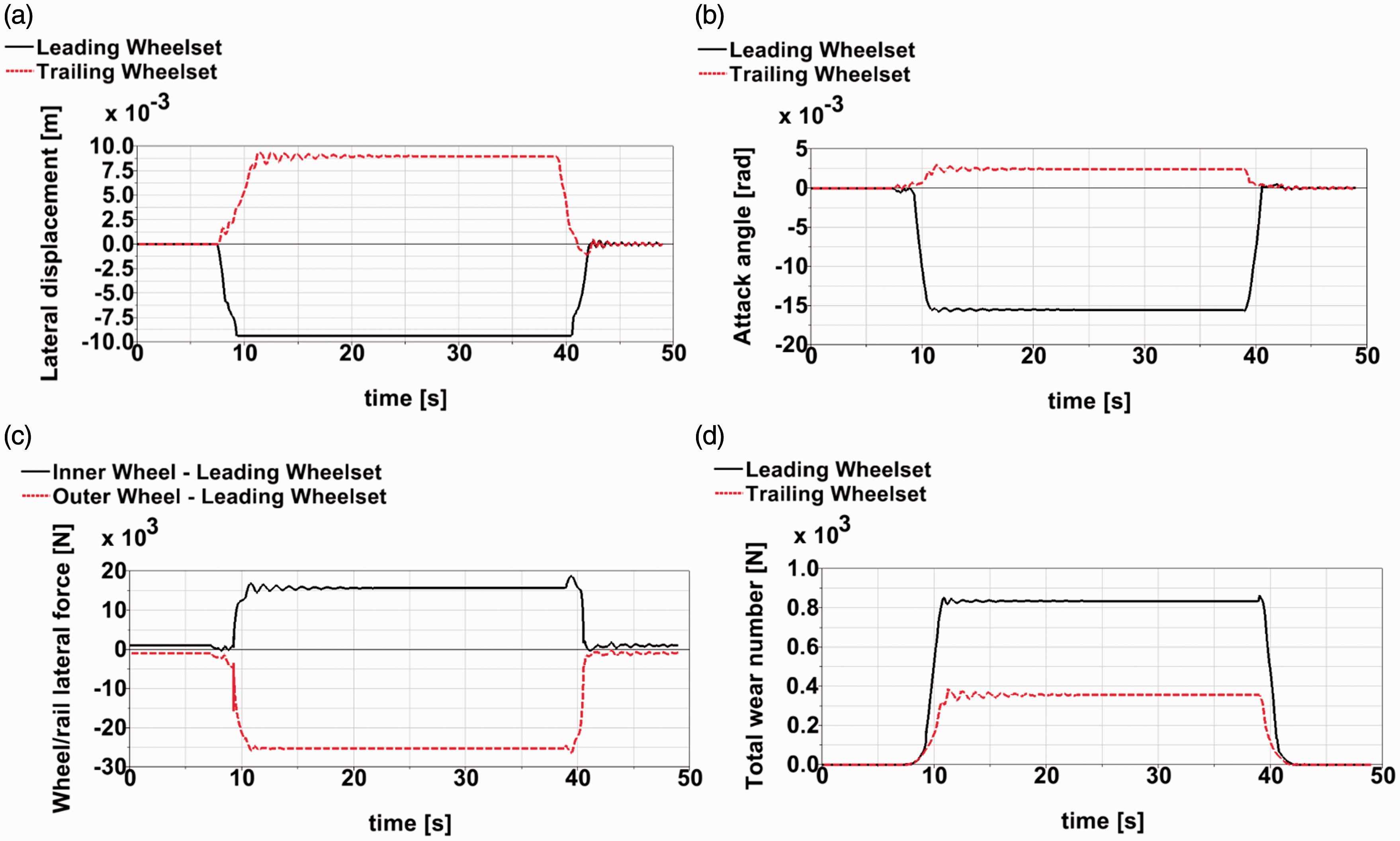
Dynamic responses of a passive two-axle vehicle in negotiation a 250 m curve at 72 km/h. (a) Wheelset lateral displacement; (b) wheelset attack angle; (c) wheel/rail lateral force; (d) wear index.
Considering the 250 m curve mentioned above, Figure 6 shows the wheelset lateral displacements and attack angles with the yaw relaxation control and the yaw compensation control respectively. From Figure 6, although the two control methods are designed for different vehicle configurations, both vehicles demonstrate consistent dynamic behaviour due to the tuning of the controllers. Different from the passive vehicle, for both control approaches (see Figure 6(a) and (b)), it can be seen that both the leading and trailing wheelsets move outwards in the lateral direction to obtain the correct rolling radius differences needed for the curve negotiation. In Figure 6(c) and (d), the attack angles of both wheelsets are very small and toward the curve centre representing a proper steering condition, which are different from the behaviour of the passive vehicle with the understeering and the oversteering. The similar attack angles of two wheelsets generate the equal lateral creep forces to balance the uncompensated centrifugal forces of the whole vehicle due to the cant deficiency in this scenario. These behaviours of the wheelsets with the active controls are very similar to the pure rolling conditions.
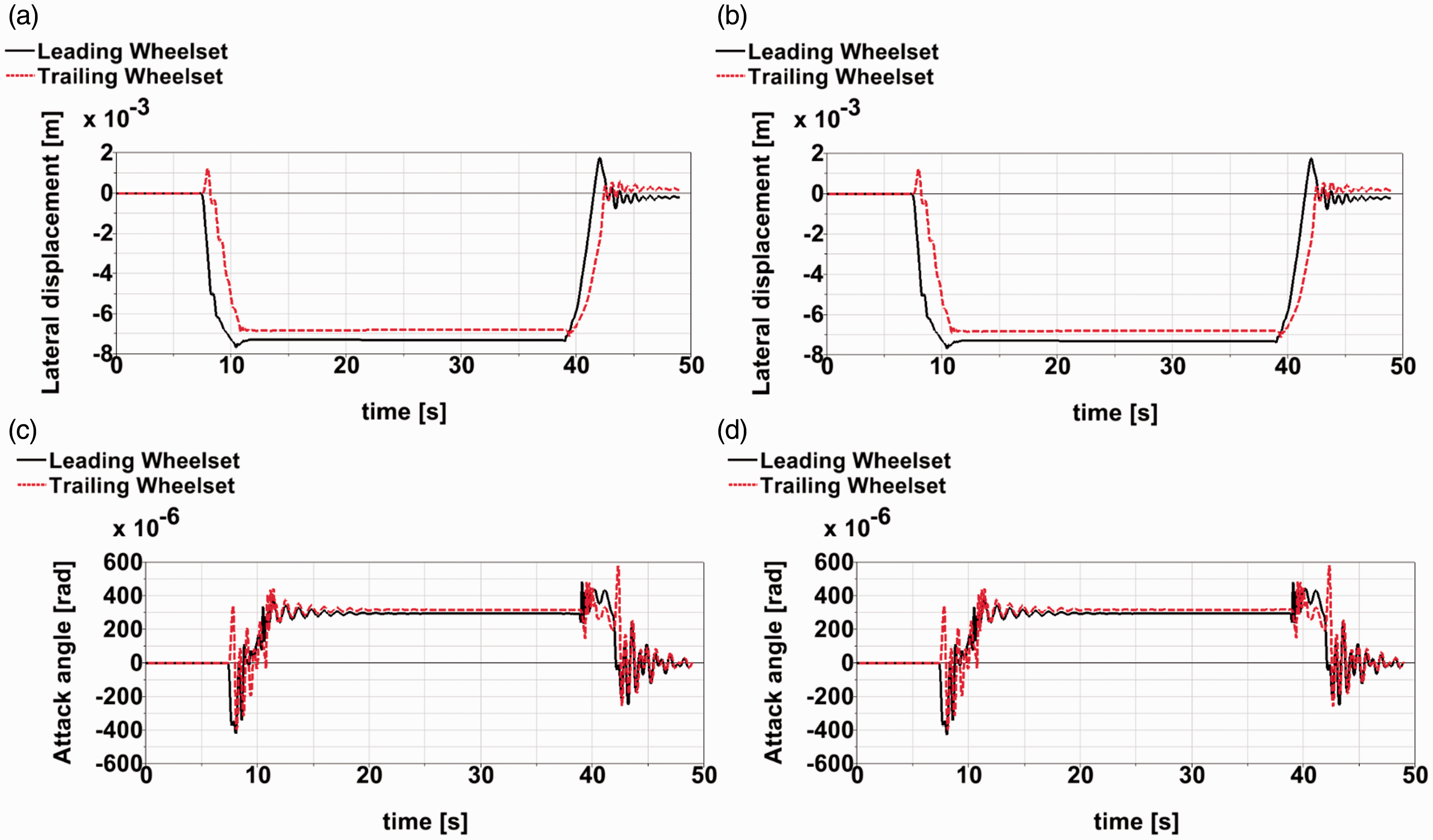
Wheelset lateral displacement and attack angle of two-axle vehicle for a 250 m curve at 72 km/h. (a) Wheelset lateral displacement – yaw relaxation; (b) wheelset lateral displacement – yaw compensation; (c) wheelset attack angle – yaw relaxation; (d) wheelset attack angle – yaw compensation.
Figure 7 demonstrates the wheel/rail lateral forces and the wear indices for the two control methods. It can be seen that much lower wheel/rail lateral forces and the significant reduction of the wears can be achieved by the active steering controls with the radial curving performances. Figure 8 demonstrates the actuation forces for the yaw relaxation control and the yaw compensation control. Due to the high yaw stiffness with yaw compensation control, large yaw torques are needed in order to steer the wheelsets to the radial positions. For yaw compensation control, the highest actuation force happens in the circular curve with the highest yaw angle. In contrast, for the yaw relaxation vehicle with a low yaw stiffness, the actuation forces of the actuators are very small in the circular curves, which is due to the adjustment of the actuation length to the equilibrium positions. In Figure 8(a), the highest actuation force occurs at the curve transition, because the low-frequency actuator needs to response gradually to the continuous change of the desired actuation length in the transition. This could also explain why the maximum wear takes place during the entry of the transition curve (see Figure 7(c) and (d)), where a higher longitudinal creep force also occurs.
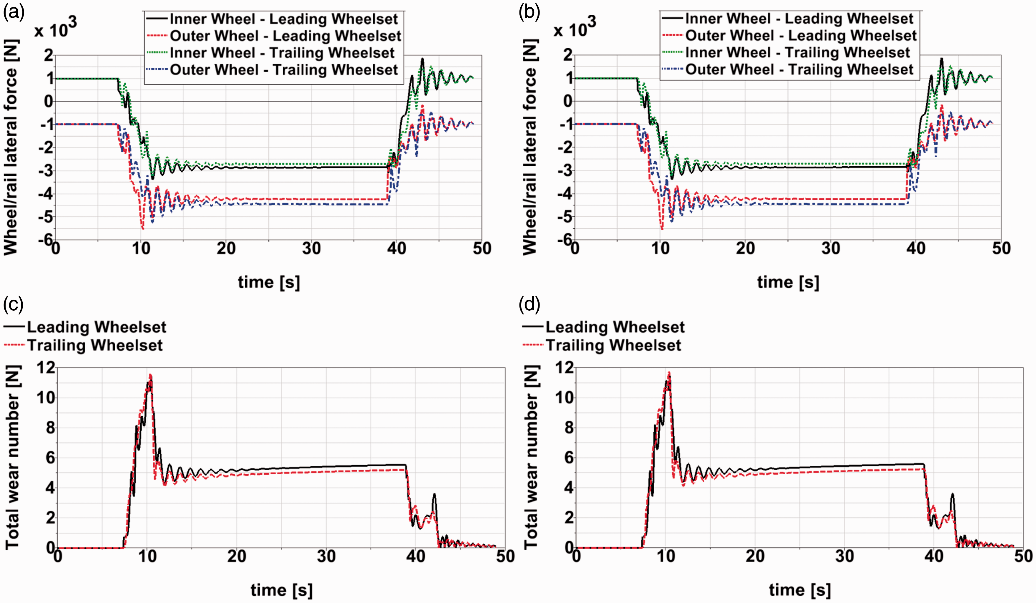
Wheel/rail lateral force and wear index of two-axle vehicle for a 250 m curve at 72 km/h. (a) Wheel/rail lateral force – yaw relaxation; (b) wheel/rail lateral force – yaw compensation; (c) wear index – yaw relaxation; (d) wear index – yaw compensation.
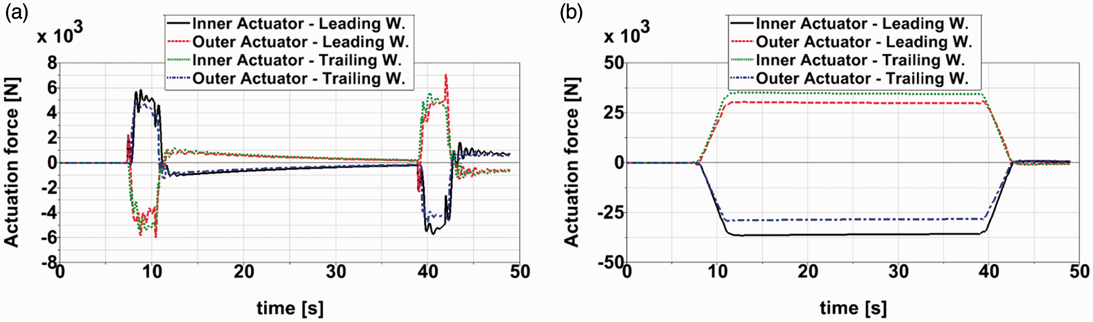
Actuation force for two-axle vehicles for a 250 m curve at 72 km/h. (a) Yaw relaxation; (b) yaw compensation.
Several other curving cases are simulated to investigate the curving dynamics of the yaw relaxation and yaw compensation systems at cant-deficiency and cant-balance speeds. Here the cant-deficiency speed refers to the vehicle speed with an uncompensated lateral acceleration of 0.65 m/s2. Since the yaw relaxation control and yaw compensation control provide very homogeneous results in most curve cases due to the tuned controllers, Table 3 lists the curving indices for the yaw relaxation control together with the actuation forces and power ratings for the yaw compensation control. It is obvious that the wheel/rail interaction indices are very low compared with the values of the passive vehicle with a high yaw stiffness. The wheel/rail wear can be significantly alleviated to very low levels with the introductions of the control approaches where the radial steering can be realized, especially for the small radius curves. For the yaw compensation control the steering torque required to negotiate the curve is inversely proportional to the curve radius, which is corresponding to the required yaw angle. For the yaw relaxation control, a higher vehicle speed leads to higher actuator loads due to the actuators’ low-frequency response. From the simulation results, it is also found for both control methods the maximum power ratings of actuators take place in the transition curves where the highest transient actuation velocities occur. In contrast, the actuator power ratings in circular curves are at very low levels due to the very small actuation velocities.
Curving indices for two-axle vehicle with active steering at cant-deficiency (d) and cant-balance (b) speeds.
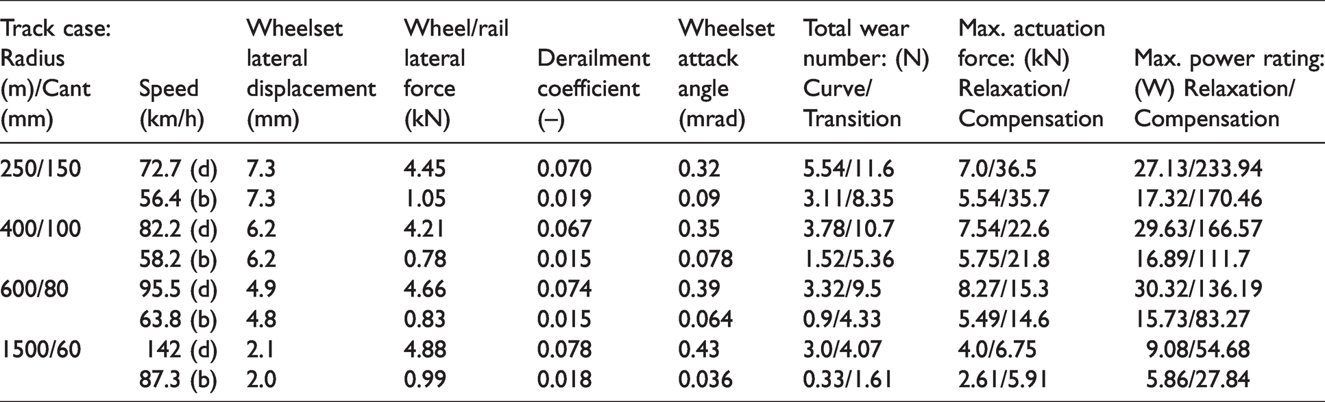
From Table 3, it appears that the high actuation force is inevitable for the yaw compensation vehicle in negotiation of a small radius curve; however, a partially compensated active force can still provide an obvious wear reduction in the curve negotiation. Figure 9 exhibits the wheelset attack angles and the wear indexes with the partially compensated active forces for the same curving case (250 m curve at 72 km/h). In this scenario, the maximum output force of the actuator is limited to 20 kN. It can be seen that even though the wheelset cannot be fully steered to the radial position due to the uncompensated suspension force, the wheelset attack angles are very small in the circular curve leading to smaller lateral creep forces. Compared with the passive vehicle, the curving wear can still be reduced significantly for this scenario due to the avoidance of the wheel flange contact. The result suggests that it is possible to apply the yaw compensation system to the ordinary high-yaw-stiffness vehicle with a limited actuation capacity to improve the vehicle’s curving performance.
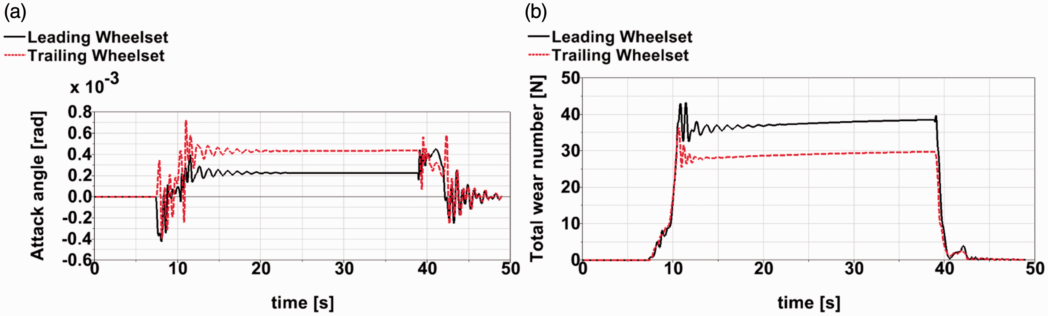
Dynamic performance of yaw compensation control with limited actuator load for a 250 m curve at 72 km/h. (a) Wheelset attack angle; (b) wear index.
Stability performance
With the yaw relaxation and yaw compensation controls, the performances of the stability and the curve negotiation can be governed by the dynamic yaw stiffness and quasi-static yaw stiffness respectively. As the improved curving performance is realized by the low-frequency actuation system, a higher critical speed can be obtained via the high yaw stiffness of the passive springs. Even though the curving behaviour and the stability performance can be regarded as ‘decoupled’, it is still very necessary to prevent the high-frequency actuation force from affecting the vehicle stability. This means the tuned controllers should be less sensitive to the high-frequency input signals. To test the vehicle stabilities with the active control approaches, the straight track with the high-speed track irregularity ‘BR – Track 270’ is adopted in the simulations. Figure 10(a) and (b) exhibits the wheelset displacements for the yaw relaxation and yaw compensation controls at the speed of 240 km/h. It can be seen that for both control approaches, the vehicles can still keep stable at this speed. By the comparison of the results with the passive vehicle with the yaw stiffness of 2.65 MNm/rad (as illustrated in Figure 10(c)), it is found all three vehicles have very similar critical speeds around 250 km/h. In contrast, the critical speed of the passive vehicle with the yaw stiffness of 0.15 MNm/rad is very low. From Figure 10(d), it can be seen that the critical speed with such a low yaw stiffness is even lower than 60 km/h. Therefore, these control approaches are capable to combine the good stability performance from the dynamic yaw stiffness and the excellent curving performance from the quasi-static yaw stiffness.
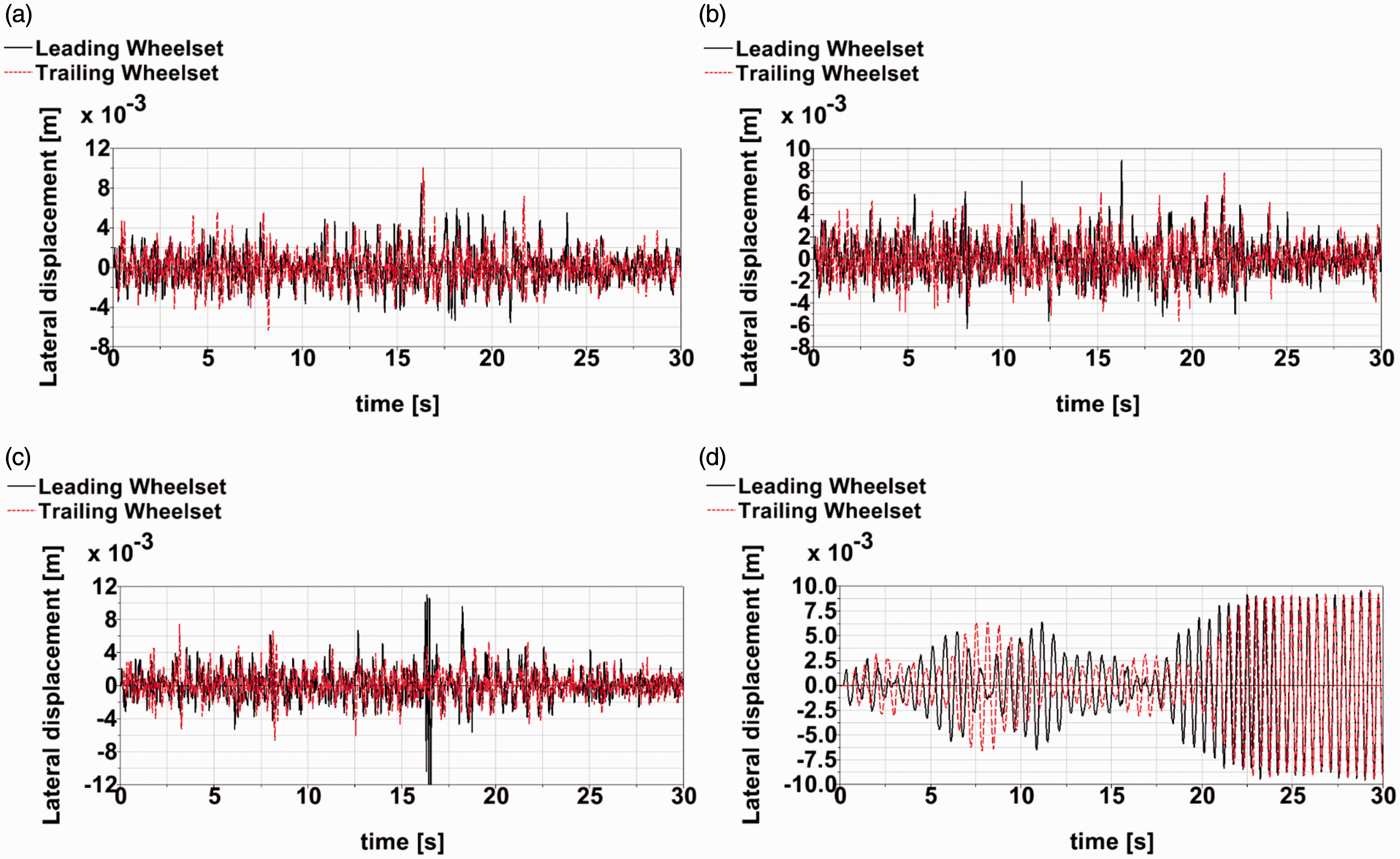
Wheelset lateral displacements of two-axle vehicle. (a) Yaw relaxation control at 240 km/h; (b) yaw compensation control at 240 km/h; (c) passive with yaw stiffness of 2.65 MNm/rad at 240 km/h; (d) passive with yaw stiffness of 0.15 MNm/rad at 60 km/h.
Conclusions
Active steering strategies for yaw relaxation and yaw compensation methods are comprehensively compared in this paper. For both control approaches, only the load cells and the electromechanical actuators, which have relatively low costs and high reliabilities, are needed to realize the radial steering performance. The difficult measurements for the wheel/rail interface quantities, such as wheel/rail lateral displacement and wheelset attack angle, can be avoided. For the yaw-relaxation control, the focus is on the enhancement of the stability for the low yaw stiffness vehicle. In contrast, the yaw-compensation control is dedicated to the improvement of the curving performance for the high yaw stiffness vehicle. For a low yaw stiffness vehicle, the radial curving of the wheelsets can be realized by simply releasing the internal loads of the actuators. However, for a high yaw stiffness vehicle, the high yaw stiffness hinders the natural movements of the wheelsets during curve negotiation. Under these circumstances, the actuators need to continuously compensate the spring loads to allow the wheelsets to steer towards their radial positions. For both systems, the steering actuation only takes place over a very low frequency range, whereas the control of the stability relies on the high yaw stiffness only functioning at high frequencies.
Considering a prototype of a two-axle vehicle, the co-simulation results for the dynamic behaviour via yaw relaxation and yaw compensation controls are compared. From the homogenous results, both control methods exhibit virtually perfect-curving performances with very low wear and wheel/rail forces due to a ‘zero torque’ strategy. For both approaches, the stability of the vehicle can be guaranteed at a high operational speed due to the high dynamic yaw stiffness, which has very limited influences on the curving behaviours. The simulation results reveal that the radial steering of the wheelset can be achieved with both low and high yaw stiffness configurations by properly tuned controllers. It also reveals that even by partially compensating the suspension forces, the yaw compensation control can still contribute to wear reduction during the curve negotiation. In fact, ‘yaw relaxation’ control can be regarded as a special case of ‘yaw compensation’ control with a ‘zero’ compensation. By contrast, a ‘yaw compensation’ control demonstrates that the application of the ‘yaw relaxation’ principle can be extended to an ‘actuator and spring in parallel’ configuration. In the scope of industrial application, the yaw relaxation control is more suitable for the newly developed vehicle equipped with an active steering system; In contrast, the yaw compensation control is more suited for the introduction of an innovative active steering device to the conventional ‘high-yaw-stiffness’ vehicle for a higher dynamic performance.
Footnotes
Declaration of Conflicting Interests
The author(s) declared no potential conflicts of interest with respect to the research, authorship, and/or publication of this article.
Funding
The author(s) disclosed receipt of the following financial support for the research, authorship, and/or publication of this article: The authors acknowledge the EU ‘Shift2Rail’ RUN2Rail project under grant agreement No. 777564 and ‘Shift2Rail’ NextGear project under grant agreement No. 881803 for the financial supports to this research.