
Abstract
Railway track switches, commonly referred to as ‘turnouts’ or ‘points,’ are a necessary element of any rail network. However, they often prove to be performance-limiting elements of networks. A novel concept for rail track switching has been developed as part of a UK research project with substantial industrial input. The concept is currently at the demonstrator phase, with a scale (384 mm) gauge unit operational in a laboratory. Details of the novel arrangement and concept are provided herein. This concept is considered as an advance on the state of the art. This paper also presents the work that took place to develop the concept. Novel contributions include the establishment of a formal set of functional requirements for railway track switching solutions, and a demonstration that the current solutions do not fully meet these requirements. The novel design meets the set of functional requirements for track switching solutions, in addition to offering several features that the current designs are unable to offer, in particular to enable multi-channel actuation and rail locking, and provide a degree of fault tolerance. This paper describes the design and operation of this switching concept, from requirements capture and solution generation through to the construction of the laboratory demonstrator. The novel concept is contrasted with the design and operation of the ‘traditional’ switch design. Conclusions to the work show that the novel concept meets all the functional requirements whilst exceeding the capabilities of the existing designs in most non-functional requirement areas.
Introduction
A novel concept for rail track switching has been developed as part of a UK research project with substantial industrial input. The concept is currently at the demonstrator phase, with a scale (384 mm) gauge unit currently operational in a laboratory – as depicted in Figure 1, and is covered by published patents.1,2 The design meets the set of functional requirements for track switching solutions, in addition to enabling multi-channel actuation and rail locking, to provide a degree of fault tolerance. The concept also offers several features that the current designs are unable to, in particular more than two routes out of a single switching element. This paper describes the formation, design and operation of the novel switching concept, from requirements capture and solution generation through to the construction of the laboratory demonstrator.
Photographs of the general arrangement of the novel track switching demonstrator in the laboratory at Loughborough University, at 384 mm gauge. Top: general arrangement. Bottom: detail of interlocking rail ends.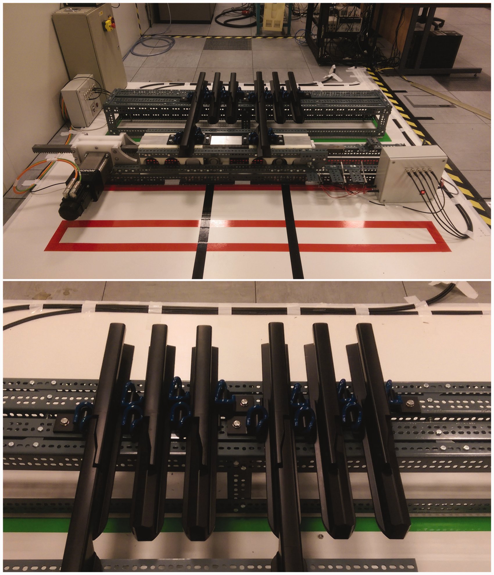
Track switches (‘turnouts’ or ‘points’) are a necessary element of any rail network. Switches enable vehicles to take many different routes through the network. A single switch, or a clustered group of switches (e.g. at a station throat), is variously considered a junction, and/or a ‘node.’ It is generally the nodes which define the capacity and performance of any transport system, as extensively explored in literature – for example in the European case by Abril et al.,
3
and by the Transportation Research Board in the US case.
4
Waterloo station throat, one of the most complex pieces of track work in the United Kingdom, is responsible for the safe arrival of just under 108 million passengers per year
5
and features 80 switches within just 500 linear metres of route. Figure 2 shows the simplest junction element – a single turnout arrangement, which also forms the simplest possible node.
Typical traditional switch layout, with sleepers/bearers omitted for clarity. (1) Line-side type electromechanical actuator featuring integral lock and detection; (2) Drive rod and drive stretcher; (3) Detection rods; (4) Switch rail toes; (5) Stretcher bars; (6) Switch rails; (7) Stock rails; (8) Common crossing (of given angle); (9) Check rails.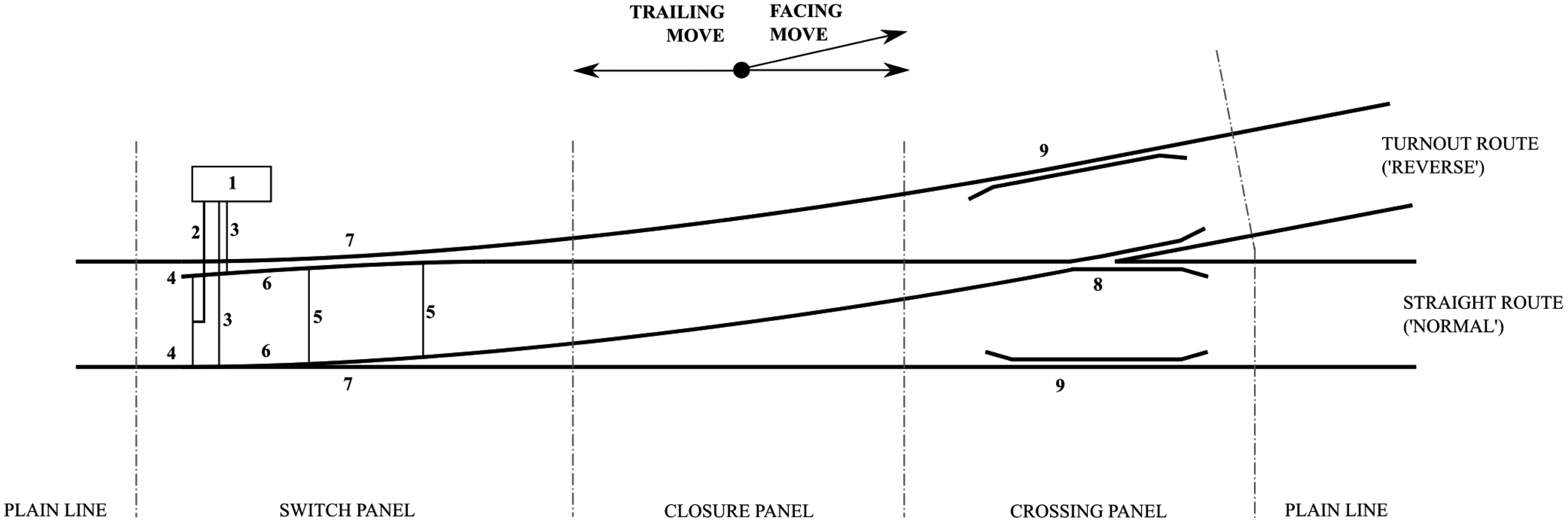
However, because of their nodal nature, track switches represent single points of failure, and their failures can prevent use of extensive sections of the network. It is for this reason that rail network performance is negatively affected by switch failures to a greater degree than any other asset. 5 Due to this, extensive plans have been put in place to minimise the impact of switch failures, involving hand-signallers at each node manually winding points and flagging trains through, as further explored later. Switches are expensive and are of complex designs when compared to the equivalent plain line sections. Their population is therefore generally optimised at design time – alongside a known timetable – in order to minimise initial outlay and substantial ongoing maintenance costs. The result of this optimisation is the availability of few, if any, diversionary options should a failure occur. This can compound the negative effects upon network delay performance, especially during timetable perturbation. Even when fully operational, switches can introduce capacity constraints due to the design of physical track components and the associated signalling systems for control and operation.6,7
On the European network, there is an anticipated move towards universal in-cab signalling. 8 With the gradual removal of other line-side assets related to signalling and control, the only remaining active line-side elements will be switches and level crossings. Switches will thus contribute to an ever-increasing portion of network delay totals without significant further work to improve performance. Open-access statistics 5 show UK passenger counts are at their highest level since re-privatisation in 1993, with some lines now running at or near operational vehicular capacity. This fact, when coupled with cross-industry initiatives such as the ‘24/7 Railway,’ 9 ‘On-time Railway,’ and increasing overnight freight utilisation as suggested in the recent IMechE Rail Freight Report, 10 further reduces the portion of time available to take maintenance possessions of infrastructure. Importantly, it is often not the physical maintenance act itself which is expensive in monetary terms, but rather the time the asset is out of use – whether this be for a planned maintenance intervention or unanticipated failure. Capacity cost is explored by Nash et al. 11 This monetary cost is associated to a nodal and, consequently, network-capacity cost.
Existing track switch systems are the result of the evolution of a single design solution dating to early mining railways in the 1700 s. 12 The operating parameters of a modern railway system are much changed from those early days. Other elements of rail systems have undergone step changes as disruptive technologies have made an impact. Notable examples are the moves from steam to diesel and electric traction, the widespread adoption of reinforced concrete for viaducts and tunnels, and the move to solid state interlocking (SSI). However, apart from small incremental changes, for instance to actuation methods, a modern track switch is of the same design and operation as those early days despite the requirements having changed significantly.
This paper considers the design and operation of track switches with a view to improving their negative impact upon network performance. Performance, in this instance, is considered as maintainability, system capacity, reliability and cost, though it is accepted that other measures could be utilised. Existing systems, their limitations and impact upon performance are considered in ‘Existing systems’ section. A requirements capture exercise follows in the ‘Requirements analysis’ section, which sets out the minimum functional set required of a track switching solution. The following section, ‘Generation and evaluation of solutions,’ presents some switching concepts generated from a series of expert focus groups, and follows the process used to down-select these options to the most appropriate. The paper then presents more detail on what has been termed ‘The Repoint solution,’ including its general arrangement, feasibility, and the qualitative benefits and drawbacks. Conclusions to the Repoint study are then presented alongside the possible future work.
Existing systems
Mechanical design
There are many methods of achieving a solution to the conflicting issues posed by track switching. However, all major railway systems throughout the world utilising the ‘traditional’ arrangement of twin steel running rails and flanged wheels have adopted a broadly similar mechanical arrangement, extensively detailed in both industry publications 12 and academic literature.13,14 This arrangement is shown in Figure 2. Switch arrangements consist of three distinct elements, or panels; namely ‘switches,’ ‘crossings’ and ‘closure panels.’
Referring to the numbered elements in Figure 2, a pair of longitudinally extending switch rails (6) are free to bend or pivot beyond a given point, and slide upon supporting plates or chairs, between two fixed ‘stock’ or ‘running’ rails (7). Actuation power and transmission is variously provided by humans and mechanical lever arrangements, pneumatics, hydraulics or electro-mechanics (1). A mechanical linkage from the power source links the two switch rails (2, 5), operating so as to open one rail and close the other, either synchronously or sequentially. In most jurisdictions, mainline switches that carry passenger traffic also feature a locking arrangement, which prevents the switch rails moving uncommanded, or when incorrectly commanded, for instance under the wheels of a passing train. However, in spring or ‘train-operated points,’ the switch rails are free to pivot in order that the wheelsets of a train in a trailing move can move the rails to provide a constantly supported route throughout. Standard design switches of different lengths and crossing (8) angles exist to satisfy different turnout speeds, longer switches generally being more complex and expensive, but capable of handling traffic turning out at much higher speeds. There are a range of generic switch designs approved for use upon British mainline infrastructure, and their properties differ depending upon purpose – the main differentiator being the design speed. Note that, whilst there is a ‘standard set’ of switch designs, in practice each installation would have its particular layout adapted for a given location. For example, a turnout placed on a curve needs differential curves on either route, meaning a different crossing angle. Designers of guided transport systems have to consider the trade-off of space, cost, line speed and capacity in selecting and locating switches for a given application. 15
Switch rails can be of the same cross section as the running rails, or in some designs, speciality ‘shallow depth’ rail. Switch rails are reduced in cross section along their length in a process termed ‘planing,’ in order that they accurately mate up against the full-section stock rails when closed, therefore providing a smooth dynamic transfer of load under a passing train. However, as the switch rails require a minimum cross section to support loads, there is some sacrifice of track alignment along one or both routes to enable the practical manufacture and wear management of the switch. Design for specific requirements, and maintenance thereof, is extensively covered in Morgan 12 and Cope and Ellis. 16
At the point where the outer rails of the two diverging routes cross, provision must be made for the wheel flanges to pass through unhindered. In common use are built-up and cast crossings, which have a gap in both running rails to allow this. As line speeds increase and curve radii become correspondingly larger, crossing angles become finer, and geometry dictates this gap – where the axle is unsupported or running on the flange – necessarily gets longer. This has led to the development of the swing-nose and swing-wing crossing, which have active components moving synchronously with the point ends in order to provide a continuously supported route. This solution has also been applied to very heavy axle loads where resultant impact forces on the crossing nose would be unacceptable. A closure panel then fills in the space between the movable switch rails and the crossing element, to provide support and guidance to traversing vehicles throughout the switch. The switch would generally be bracketed on all routes by sections of plain line, but in more complex junctions – especially those where footprint is restricted – switches may be adjacent or even overlap.
Signalling and operational rules
Switches remain in position and locked until commanded to move via the signalling system. The position of the blades, and the integrity of the position lock, is continually fed back to the interlocking via a subsystem known as detection. When changing position, traditional switch designs move through a state, which can be considered dangerous due to the inherent derailment risk, when the moveable blades are between the two set positions. Trains can be issued a movement authority (either by radio in communication-based signalling systems, or else by a line-side signal aspect) to pass the switch only once the movement process is complete. Switches under UK practice follow a move–lock–detect cycle. This means, upon command from the interlocking, the actuator moves the blades to the correct position, then locks them in place, then detects the position of both blades and the integrity of the lock before transmitting this information back. This process normally takes several seconds; around 8 s is allowed in British signalling practice. A more detailed discussion of the British practice of switch control and operation is provided in ‘Principles of power point control and detection.’ 17 Additional time is often required for remote interlocking processing and transmission of the authority. As the switch represents a derailment danger when between positions or unlocked, under no circumstance can the switch be moved within a previously issued movement authority. For instance, a switch actuated within the effective braking distance of the train, which subsequently fails to fully change positions, could cause derailment or a potentially disastrous misrouting. As nodes become more complex, this requirement becomes increasingly restrictive due to safety rules surrounding actuation of switches on adjacent lines and around conflicting moves, e.g. flank protection. 18 There is generally an element of the interlocking responsible for releasing the switch to be reset some time after a train has passed, for example train operated route release (TORR). Crucially, the signalling system is designed to pass back no more information on the current state of a switch than whether it is locked and detected normal or reverse, or not detected in either position. 17
Capacity
These restrictions upon movement lead to a reduction in the theoretical maximum capacity of a junction below what could be expected from an equivalent section of plain line. Additional capacity is lost in installations where the turnout route has a speed restriction below that of the straight route; in these cases some braking or acceleration must take place upon the mainline, which further consumes the available capacity. It is not possible to define capacity as an absolute value, thus it is not possible to calculate, in the general sense, what this capacity restriction equates to. Capacity consumption is the method utilised by the industry, as detailed in various literature,3,4,11 and further explored in standard UIC406. 19 The value for capacity consumption at a junction is linked to the proposed service pattern through that junction over a given time period. Previously published work has explored and, subsequently, modelled these capacity constraints and methods to alleviate, both from the authors of this paper,20,21 and others, for example Liu et al. 22 The application of moving block signalling schemes will not necessarily alleviate capacity constraints at junctions, as the fixed obstruction provided by a switch causes the signalling operation to revert to fixed block at this point. 23
Reliability
Incident count and subsequent delay minutes incurred for infrastructure asset failures between 2008–2014 upon UK mainline network, for top 18 incident categories by total count.
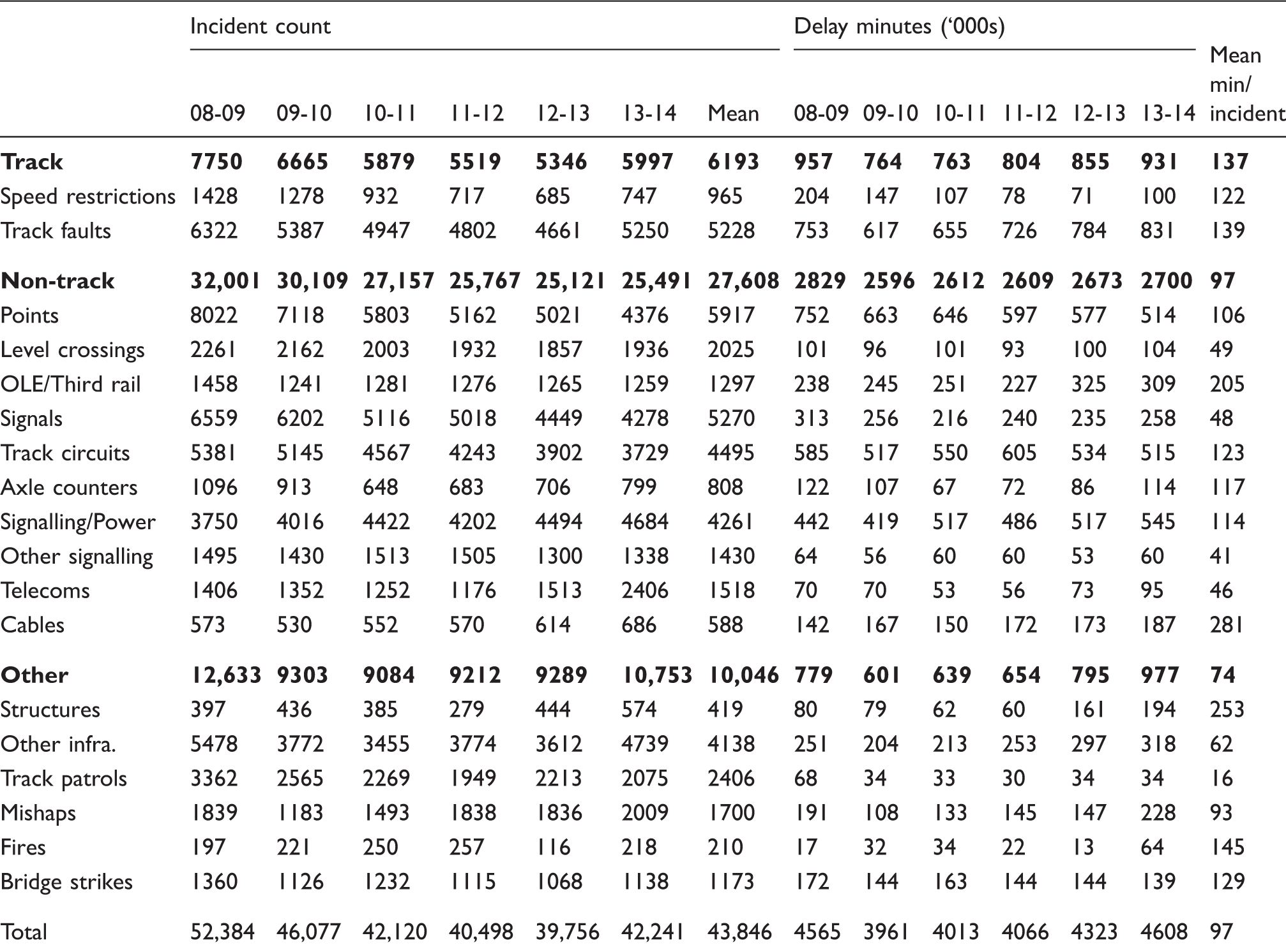
Source: ORR Data Portal. 5
The data shows that, for every published year apart from 2013 to 2014, points failures contribute the highest total of delay incidents. However, it can also be observed that points failure incidents, and subsequent delay minutes incurred, have fallen significantly over the same period. This is due, in part, to Network Rail’s Intelligent Infrastructure programme, more details of which are provided by Silmon and Roberts. 14 This programme aims to remotely monitor switch installations in order to detect faults in the period before they develop into system failures. However, there is a limit to the projected benefit without the provision of a backup system to take over if a fault is detected, as the switch still has to survive in a serviceable state until a maintenance team can attend. Should the fault detection algorithm be too sensitive, the number of false positives may serve to offset much of the benefit. Isermann 24 provides a comprehensive discussion of the benefits of fault detection versus fault tolerance.
Human factors
Considering the whole life-cycle of switches and crossings, there are several cases where humans come into contact with the system. Design, installation and commissioning, and end-of-life decommissioning are of consideration. Choices regarding the type of machine and location, and the practicalities and practices at installation are known to have a significant effect upon the performance of the switch. These will not be discussed further in this paper as the issues would affect all designs and there is much ongoing research into this field. 25 The primary human contact through the working life of the switch installation is via signallers, who operate (but may be remote from) the switch, and the maintainers, who visit regularly to perform inspections, maintenance and adjustments, but are generally unable to operate the switch locally. A systems context diagram of existing track switch solutions is shown in Figure 3. It identifies the main actors in the lifetime of a switch installation, and with which subsystems they primarily interact.
The signaller
In mechanical signal boxes, the signaller manually sets a route through a junction by operating levers. Levers are connected to points and signals, some of which may be out of sight of the signaller. If the switch was blocked, for instance, the signaller would receive feedback through the lever as he/she would be unable to complete the movement. The length of the mechanical rodding used to transmit the motion has a practical limit of around 200 m, so in the event of any issues the signaller may be able to inspect the site to establish the problem. In a more modern control centre, the signaller’s interaction with a switch is several levels removed. The signaller commands a route to be set by telling a computer or control panel the entry and exit points, and the control system then commands switches to move to correspond to this. The panel indicates the route is in the process of being set, generally with a flashing light, until the route is set at which point the lights change colour. If any of the switches fail to move to the commanded position, the lights continue to flash, and there is little the signaller can do apart from retry the route set command or contact the maintenance organisation. In the latest systems, automatic route setting (ARS) abstracts the signaller one layer further, in that human intervention is expected only when there is a failure or unresolvable conflict of traffic. Thus, no matter what the signalling installation type, the signaller is the daily user of the switch but acts at a level abstracted from its actual operation. The level of abstraction increases the more modern the signalling system, and this can compound issues when there is a switch failure. 26
The maintainer
Switches require a level of inspection and maintenance in excess of plain line due to additional moving parts.16,27 Failures of individual subcomponents almost inevitably lead to whole-system failures as there is minimal, if any, designed-in fault tolerance. Hence, switches are subject to careful inspection and maintenance regimes. UK switches undergo a rigorous and highly prescribed maintenance schedule to ensure all safety critical components are in good order. This involves two independent teams – Signalling and Permanent Way Departments – visiting each switch; the latter at a frequency of once per week. The maintenance organisations are not able to move the switch locally; instead they contact the signaller to effect this for them. In addition to time-interval maintenance, the maintenance organisation has a rapid response unit, which is responsible for attending any asset failures, including switches. These teams may have a large area to cover and, if several incidents occur at once, response times can be over 1 h. To reduce this impact, recent literature shows extensive research has been conducted into condition-based maintenance of existing designs, 13 and Network Rail, the UK infrastructure custodian, is currently rolling out condition monitoring equipment across its active assets. However, even condition-based switch maintenance requires a possession of the line and human intervention which is not always possible. With the drive in the United Kingdom towards a 24-7 railway, any planned maintenance requiring an exclusive track possession must occur in ever shrinking time windows. In any case, it is unlikely that regular inspections can be reduced to zero, due to the design of switches having several safety concerns for which regular inspection is the mitigation. This includes, but is not limited to, stretcher bar to switch blade mountings (see (5) in Figure 2), which when loosened are almost guaranteed to cause a facing move derailment.
For any switch redesign to be successful, concern must therefore be given to maintainability. It would be of specific benefit for any proposed design to:
Enable the continued and safe functioning of the switch despite a given number of known faults in subsystems. Communicate known faults to a control centre such that repair work can be managed and scheduled appropriately. Enable as many maintenance operations as possible to be conducted without maintenance possession. Enable as many maintenance operations as possible to be mechanised or conducted off-track to minimise risk to personnel, improve output and reduce costs. Use a minimum, commercial off-the-shelf (COTS) component set such that spares can be carried without needing adapting to specific switch installations.
Requirements analysis
Overview
The requirements of the system reduce to a simple set of key technical requirements. Those requirements are a combination of those for a track system, those for a safety-critical asset, and those for a mission-critical asset. The track system function is to support and guide vehicles. The active element has two functions: to direct vehicles along the correct path; and to confirm the route to the interlocking, or provide information that the switch is unsafe. This operation must be performed within a given timeframe. Traditionally, these have been the only requirements of a switching solution. However, given the high performance standards of a modern railway and the criticality of switch availability, another necessary requirement could be included, namely to communicate back to maintenance resources the current ability of the switch to perform its task, and the requirement for any immediate intervention. The following requirements set is proposed.
Essential requirements of a track-switching solution
The switch shall adequately support and guide all passing vehicles (from relevant track standards
28
).
It shall be strong enough for the required static loading. It shall be strong enough for the required dynamic loading. It shall guide the wheelsets with maximum deviations as specified for the given track quality. It shall manage the wear and degradation of support and guidance elements to allowable levels. The switch shall direct vehicles along the path specified by the interlocking.7,17
When commanded to, and not otherwise, it shall align any movable elements so as to direct the wheelset of a vehicle along the specified route. When commanded to, it shall align any movable elements for the requested route within a specified timeframe. It shall ensure all wheelsets of a passing vehicle are directed along the same route. The switch shall confirm to the interlocking the route vehicles will be directed along, and that all active elements are safe for the vehicle to pass.7,17
It shall provide feedback to the interlocking that the requested route is set. It shall provide feedback to the interlocking if the requested route is unable to be set. It shall provide feedback to the interlocking on (3a) and (3b) within a given timeframe. The switch system shall provide information to maintenance organisations regarding the future projected ability to perform requirements (1), (2) and (3).
It shall monitor wear of wear-susceptible parts and adjustment of adjustable parts. It shall communicate current state of wear and adjustment to maintenance organisations. It shall calculate and communicate the remaining time of useful operation of the asset without maintenance intervention. It shall achieve a given level of reliability commensurate with the operations at the node. It shall minimise the amount of time the node is unavailable due to maintenance activity, and the amount of time maintainers must spend trackside.
How do traditional switches perform these functions?
Referring to the functions specified above, traditional switches have evolved a particular design and operation in order to meet given requirements.
Requirement (1) is generally achieved by designing the track elements of the switch to be of equivalent rating to the surrounding plain line and traffic requirements. However, in order to meet (1c), in some cases this has meant relaxing the standards, notably around the switch toes, in order to prevent having infinitely thin blades at the point of intersection of routes. 28
For requirement (2), routing of vehicles is currently achieved by the combination of an actuator and two moveable switch rails, as detailed in the ‘Existing systems’ section. The actuator acts to close one switch rail against the corresponding stock rail, and open the opposite to create a flange-way. The same actuator, by means of a mechanical arrangement, then provides a locking function to prevent uncommanded movement of the rails. However, the use of a single actuator without any level of redundancy means that component failures may easily prevent the actuation elements performing this requirement on demand, even with appropriate maintenance as per (4).
Requirement (3) is provided through the detection elements of existing designs. Components essentially forming limit switches indicate that the two movable switch rails are in the correct position, and that the lock preventing movement to fulfil requirement (2c) is engaged. This signal is then passed back to the interlocking. If the switch is unable to be set for a particular route, then not all of the limit switches can be engaged, thus no detection signal is transmitted, and after a given timeframe as allowed for in (2b), the signaller would deduce there was a problem with the switch. Note that switches do not, in the signal to the interlocking, differentiate between ‘currently moving to desired position’ and ‘unable to move to desired position,’ as both states appear the same to the available set of limit switches.
Requirement (4) is perhaps the requirement subset which is most lacking in existing switch designs, as the requirement itself has only evolved with the enhanced performance requirements of a modern railway system. There has been a drive in the United Kingdom, over the preceding few years, to retro-fit condition monitoring equipment to better meet (4a) and (4b). 9 However, despite this, the safety-critical monitoring element is still achieved by sending teams out to complete regular inspections (as high a frequency as once per week), though this clearly clashes with requirement (4e). Requirements (4c) and (4d) are currently not catered for; however, work in the field seeks to improve these aspects, as discussed above. 14
Non-functional requirements
There are further requirements which need to be established, but can be considered non-functional. Whilst all switching solutions need to satisfy the full set of functional requirements, non-functional requirements form a set of trade-offs. For instance, UK and European infrastructure owners have goals to reduce the hours teams must spend working line-side with live traffic for safety reasons. There are political pressures to reduce the monetary costs of building and maintaining infrastructure.
29
In some locations, space is at a premium, and the alignment of track, or capacity, is sacrificed as there is not the space to fit a switch of the ideal specification. These elements form trade-offs, which are unique to each location. Non-functional requirements were considered and the most significant listed:
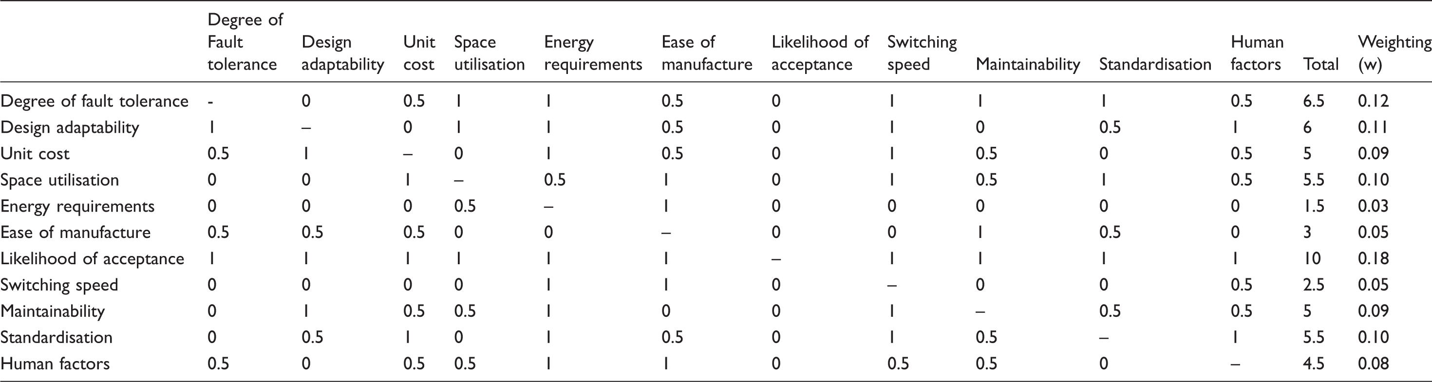
Degree of fault tolerance: How susceptible is the design to a single fault/failure rendering the switch unusable? How long could the switch survive in a usable state until such a time as repair can be performed? Design adaptability: Switches must handle many types of traffic at many speeds. Whilst it could be argued many different designs could fulfil these different purposes, a single, adaptable design is preferable. Cost: Monetary cost of the solution, estimated using engineering judgement. Space utilisation: Physical footprint of the solution. Energy requirements: Any actuation must require a level of energy which a reasonable existing power supply installation is capable of providing Ease of manufacture: Able to be mass-manufactured using existing techniques and processes. Likelihood of acceptance: The rail industry has strict process and standards regarding the design of products for use upon the network. Switching speed: The faster the switch can change positions, the better. Maintainability: There are pressures to reduce the amount of time personnel spend performing maintenance tasks trackside. Does the design help to achieve these ambitions? Standardisation: Can the design maximise the use of COTS components, or minimise custom components? Human factors: Maintenance teams and trespassers may be exposed to movable elements of the switch. How big is the risk posed compared to that currently present?
Non-functional requirements ranking and weighting matrix. If row is more important than column, then cell is equal to 1; of equal importance, 0.5; of lesser importance, 0.
Generation and evaluation of solutions
Solution generation
A cross-industry focus group was assembled on three occasions through 2011–2012, to generate candidate track switching solutions. The panel was UK-focussed, due to the funding arrangements, but with substantial international experience. Membership comprised personnel from rolling stock and infrastructure backgrounds (Track and Permanent Way), across: design; maintenance; operations; ‘head office’ (modelling and performance) functions; and regulatory bodies. Further to these sessions, a series of remote and face-to-face meetings was conducted with other stakeholders within UK infrastructure custodians – namely Network Rail and London Underground. Academics with a background in reliability engineering and fault-tolerant design were also invited to contribute.
These sessions resulted in just under 420 individual ideas related to improvements to switches and crossings, covering their physical design, signalling and operation and maintenance activities.
Initial filtering and down selection
The first filter for down-selection was to exclude any ideas which were mechanically implausible. Construction/operation of some ideas will not be possible, and these ideas must necessarily be rejected at an early stage.
Secondly, any ideas which would require wholesale modification of the entire rolling stock fleet were excluded. These included, for example, the removal of all wheel flanges or steerable bogies. It is generally accepted that one option, ‘vehicle-based switching’ (VBS) may deliver higher levels of performance than track based switching; primarily as system failures are generally limited to a single vehicle. 30 However, the panel felt the development of such a solution in the United Kingdom would be prevented by the fragmented nature of rolling stock and related interface standards ownership.
Thirdly, any ideas which would require more than 20 years estimated ‘time to market’ were excluded. For example, novel vehicle control solutions which require European Rail Traffic Management System ERTMS Level 3/4 or higher. 23 The academic team were advised by regulatory bodies that the rail industry would be very unlikely to adopt such solutions due to the cyclic nature of development funding in the sector.
This left around 60 solution options to be investigated and ranked.
Ranking solutions
A selection of the highest scoring remaining solutions is briefly presented here.
A: ‘The Track Substitution Switch’: A whole section of track is lifted out of place and replaced with another section B: ‘The Single Flange Controlled Switch’: Only one flange of the wheelset is controlled through the switch, the other free. C: ‘The Wheel-face Switch’: Rails move into place which act upon the face of the wheel to select a route D: ‘Interlocking Rails’: A specially crafted rail end design locks itself in place when under the mass of a train E: ‘The Stub Switch’: Reverses the components in a traditional switch, and has stub ends which bend or move between positions to select route F: ‘The Over-Running Rail Switch’: Uses a removable ramp to lift one wheel over the corresponding running rail G: ‘Raising and Lowering the Switch Rails’: Existing switch rails move laterally, but it is possible to raise and lower them into position instead. H: ‘The Swing-nose Switch’: A moveable element similar to that in a swing nose crossing acts to select a route for the flange to follow. I: ‘The Hopping Switch’: Switch rails move vertically between positions such that when at rest they have dropped into a groove preventing them from moving. J: ‘The Spring Switch’: A passive design which always directs facing traffic in one direction, but allows trailing moves from both by allowing the switch rails to spring out of the way. K: ‘Hopping Stub Switch’ (D, E and I Combined): These concepts could be combined to provide the potential benefits of all three.
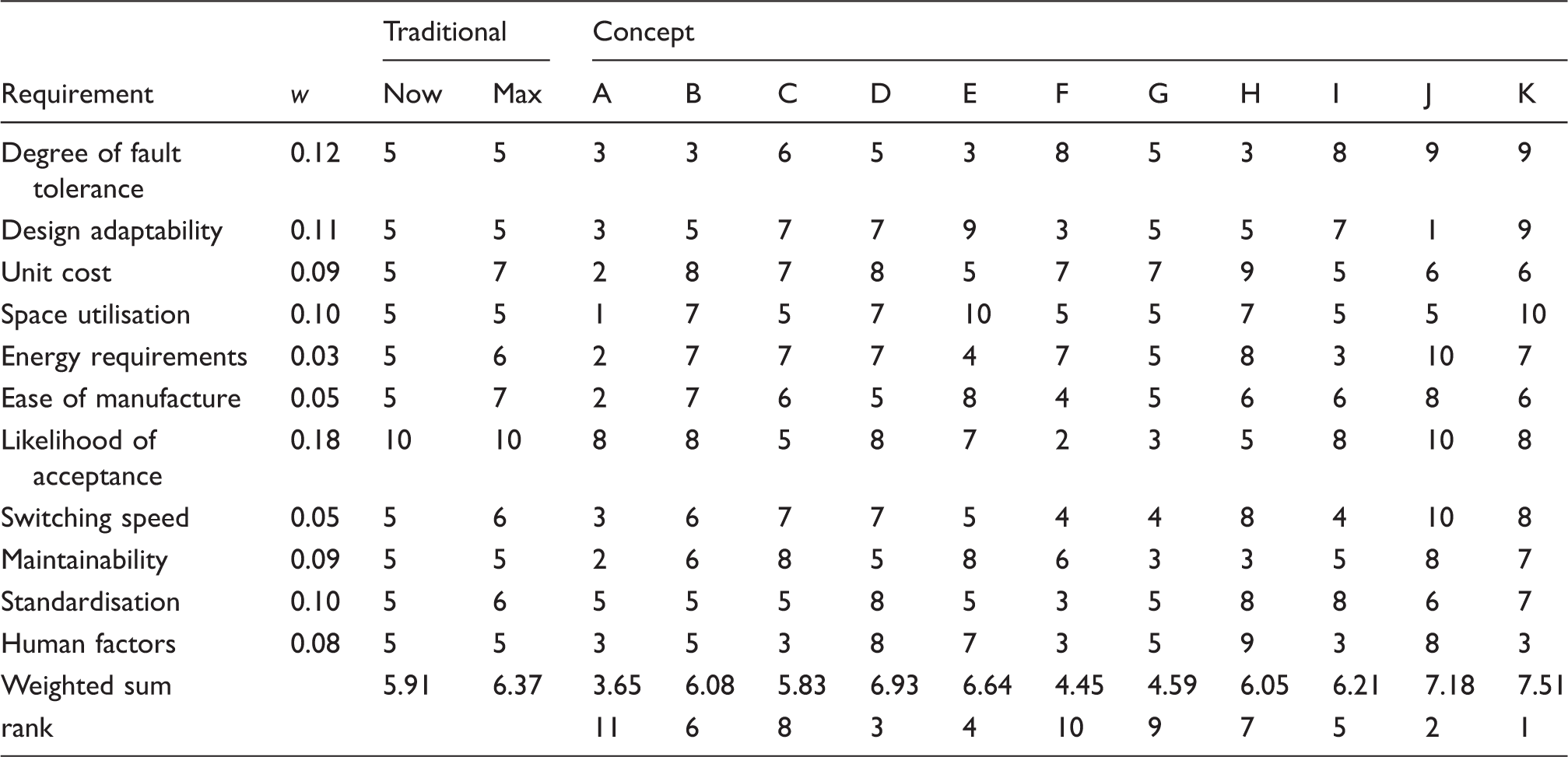
Each design was then scored out of 10 in each area of the non-functional requirements, using engineering judgement. The results of this scoring are shown in Table 3. It can be seen that concept K scores most highly. Concept J also scores highly, especially in the areas of energy consumption (zero) and switching speed (instant). This is to be expected for a passive solution, though it is clear spring switches could not be used in every location. However, the weighted matrix places less emphasis upon those areas. Concepts D and E also score highly. Concept K is a combination of concepts D, E and I, where each offers a unique set of benefits, but are complementary as none of the features of the individual concepts prevent them being used together. It is this combination of designs which was therefore selected for further investigation. This concept is now termed the ‘Repoint’ concept and is discussed in further detail in the following section.
Systems context diagram for Railway Track Switching. Interactions between the switching subsystems and external systems are shown. The most relevant interactions between systems entirely outside the system boundary are also indicated, though these interactions are not exhaustive. Results of the weighted scoring exercise, including concept rankings.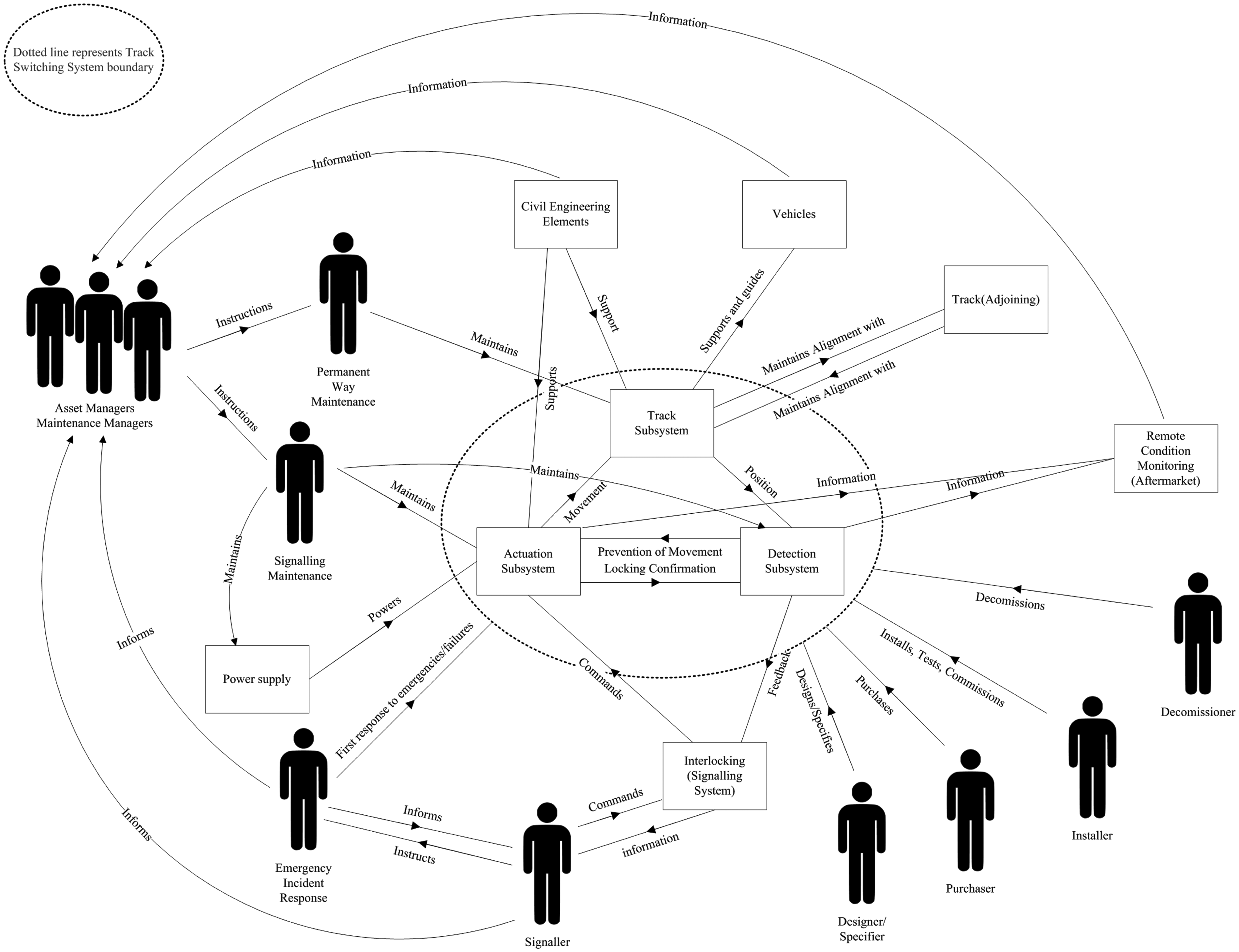
The ‘Repoint’ solution
General mechanical arrangement
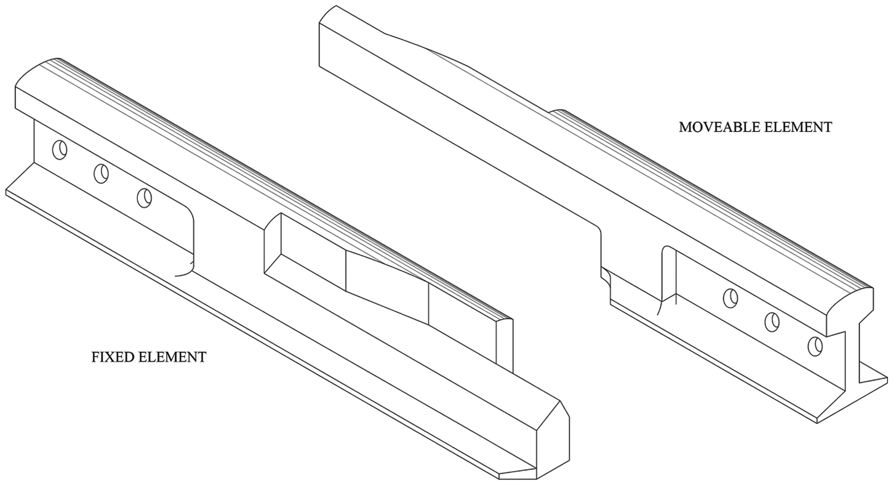
The design is based around an arrangement known as a stub switch. The stub switch reverses the elements in a traditional switch, and replaces the long, planed down switch rails shown in Figure 2 with short, stub-ends formed of full section rail which are able to move between positions. Figure 4 shows the general arrangement of a ‘Repoint’ stub switch, with an optional second turnout route shown. A bank of actuators is responsible for moving the full-section switch rails between each position. The actuators bend the rail between each position, from a stationary point, beyond which the track can be considered plain line. There is no hinge. To ensure the correct bending profile, it may be necessary to alter the cross section of the rail around the stationary point, and an established method such as flange relief could be applied to achieve this. Where the open, moving rail ends interact with the static rails in the track panel, a novel design of interlocking rail end is necessary. This is to allow the expansion and contraction (with temperature variation) of all rails in the assembly, whilst still providing support and guidance for wheelsets. The general arrangement of this rail end is shown in Figure 5. As the rail ends interlock to provide a consistent track alignment, when moving them between positions the required actuation path involves lifting them out of register.
Repoint stub switch general arrangement with electro-mechanical in-bearer type actuators, with most sleepers/bearers omitted for clarity. Numbered elements as follows: (1) In-bearer type electromechanical actuators featuring integral passive locking elements with detection system; (2) Bearer featuring integral passive locking elements; (3) Bendable, full-section switch rails; (4) Interlocking rail ends; (5) Line-side processing and condition monitoring cabinet; (6) Power, position and monitoring signal cables; (7) Stationary point of curve; (8) Common crossings (of given angles); (9) Check rails. Interlocking rail ends. Holes are shown for possible bolted mounting, but units could be welded in place. The chamfer in the horizontal plane locates the rails laterally, meaning the moveable rails require lifting to disengage this chamfer before they can be moved laterally. The concept allows for some longitudinal movement in the rails in the same way an expansion switch operates, with the chamfer in the vertical plane giving a smooth transfer of load from one rail to the other.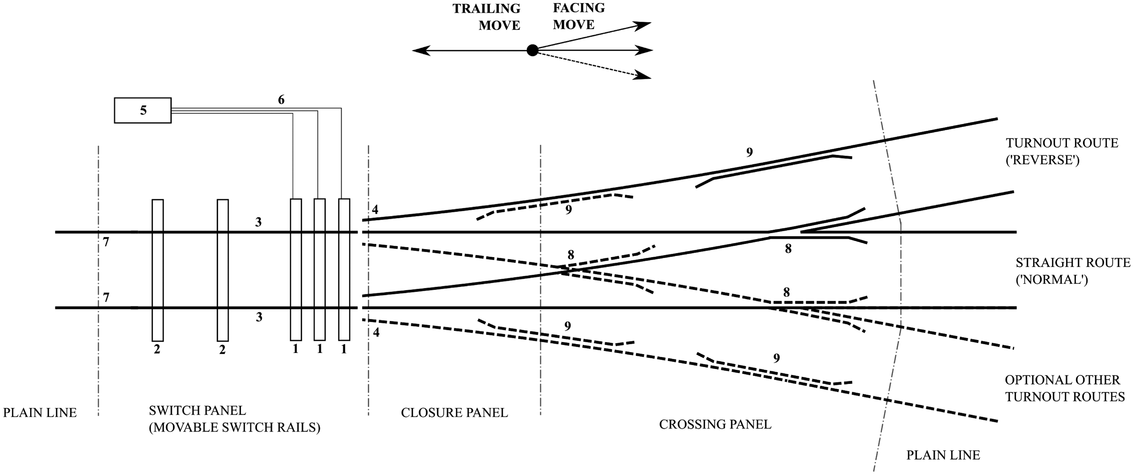
Actuation is provided by a multi-channel actuation bank, with the actuation elements contained within bearers near the movable rail ends. Each actuator is capable of moving the switch alone. Triplex redundancy is shown in Figure 4; however, the exact number of actuators required could be tailored to the particular requirements of each location on the basis of an operational reliability figure. A line-side processing and condition monitoring unit, abstracted from the interlocking, provides control of the elements. It is also responsible for isolation of suspected faulty elements, and may feature controls for maintenance teams to do the same. The moveable rail is supported upon said actuator-bearers, which transmit the static and dynamic loading from vehicles to the track substructure. These bearers have a movable top surface, termed a ‘shuttle,’ to which the rails are attached using appropriate traditional rail clips. The lower casing of the actuator-bearer is embedded in ballast, or affixed to concrete in the case of a slab track installation. Vehicle load is transmitted from the rails, through the shuttle and then locking blocks to the bearer casing, where it distributed to and through the substructure in the usual way. Additional support may be required at the rail ends, and the support conditions here are the subject of further study.
Multi channel actuation is provided through an arrangement which has been termed ‘passive locking.’ The theory of passive locking is that when the rail is in one of its stationary, lowered positions, it is unable to move in any direction apart from directly upwards. There are no significant uplift forces present compared to other axes, and a significant net downward force when the mass of a train is present. It is a requirement to lift the interlocking rail ends to disengage them. When the track is lifted, it is free to move laterally, but not longitudinally. Thus, the rail hops between adjacent positions. If an actuator is isolated for whatever reason, the adjacent unit(s) can still actuate the switch, as the lifting action will unlock the isolated unit. It is this feature which enables redundant actuation to be provided as part of the ‘Repoint’ concept, something not possible with the conventional switch. There are many ways to provide drive inside the actuator units, and one simple method utilising a rack, two cams and followers is shown in Figure 6(a). This is the method chosen for the laboratory demonstrator described in the later section. The actuators are enclosed in sealed, line-replaceable units. The motor and gearbox arrangement is back-drivable, in order that should a failure occur between positions, the mass and spring force of the lifted rail will cause the switch to drop back into one of the safe, lowered and locked positions. Modelling has been conducted, detailed in other papers, e.g. Ebinger and Wright
31
and Wright et al.,
32
to verify that the approach is mechanically feasible.
Cross sections of each actuator-bearer. (a) shows internal elements related to the actuation system chosen for the demonstrator system, though other arrangements to provide the necessary lift-move-drop curve would suffice. A motor and sealed gearbox drive a toothed rod, which acts upon two cams; a 180° rotation of the cams causes the shuttle to move between adjacent routes. (b) shows the associated locking elements, which would be present inside each bearer alongside (a).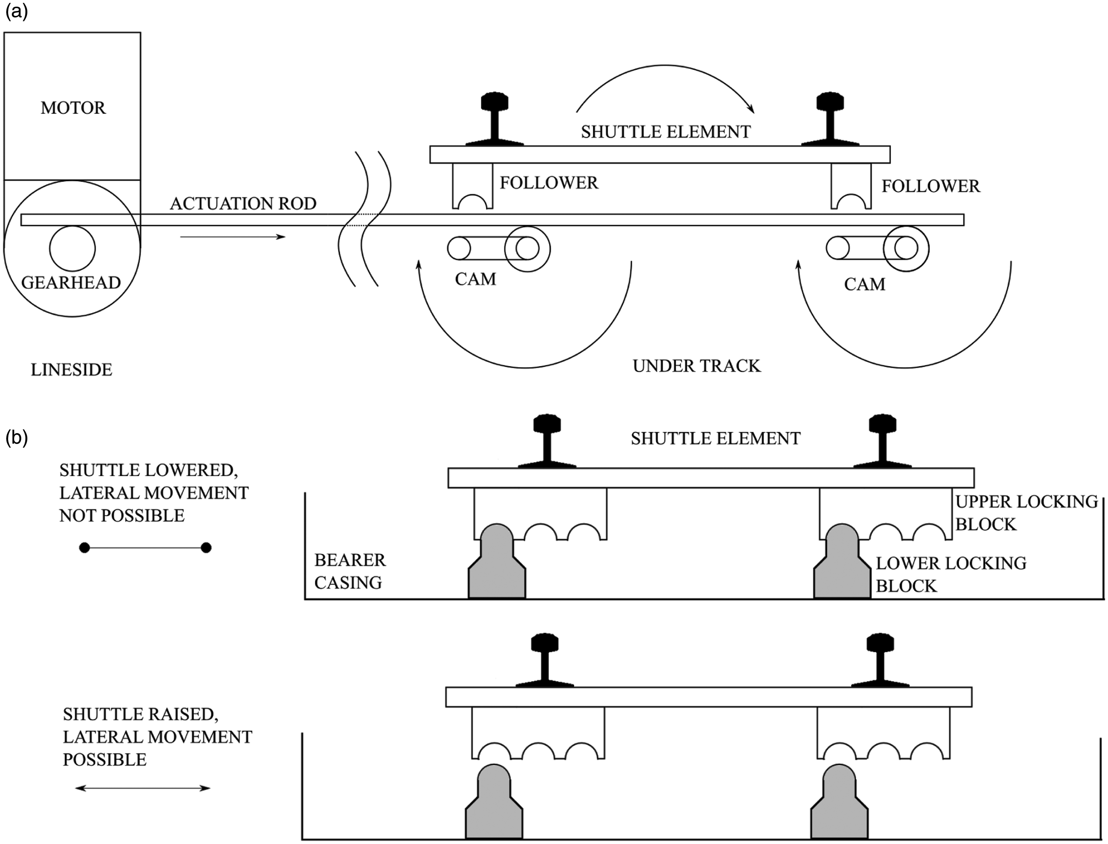
Satisfying the requirements
Referring to the functional requirements specified in the ‘Requirements analysis’ section, we can postulate that the Repoint solution can meet all requirements and, therefore, exceed the extent to which existing systems meet the requirements with regards several elements:
Adequately support and guide all passing vehicles:
The solution is constructed of the same, full section rail as surrounding plain line. Dynamic loading is reduced due to the track alignment through the switch being of full-section rails. The solution has full-section rail throughout, accurately aligned at each sleeper/bearer, exactly as for plain-line. (1b) means that wear could be reduced. The wear element is now the interchangeable and standardised chamfered rail end, rather than long switch rails. Wear will be easier to manage and the rail ends are replaceable as a relatively short pair. Direct vehicles along the path specified by the interlocking:
The switch can move to a new route when commanded; however, it can unambiguously form a route when commanded due to the multiplicity of actuators. The concept can switch at a faster rate as the actuators do not have to be sized to overcome the variable friction on plates, and instead store energy in a spring (the rails) which can be used to assist in the motion for the second half of the throw. The locking elements of each bearer ensure the switch remains locked on a single route for traffic until commanded otherwise. The switch is even less likely to move under the mass of a train, as the mass acts downwards and thus further locks the switch. The mechanism eradicates the ambiguous failure state between routes, for facing moves. Confirm to the interlocking the route vehicles will be directed along, and that all active elements are safe for the vehicle to pass:
Limit switches can provide confirmation to the interlocking that each bearer is in a given lowered position, and therefore which route is set. The local condition monitoring processor can determine if there is an issue preventing a route being set through comparing signals, and indicate such to the operator. The incidence of ‘unable to set’ would fall due to the parallel-channel actuation and reduced chance of blockages. Provide information to maintenance organisations regarding the future projected ability to perform requirements (2) and (3):
In-built condition monitoring, for the function of the multiply-redundant actuation, monitors wear points. Line-side processing can communicate switch prognosis through existing channels. See (4b). The redundant elements enable a higher level of operational reliability to be achieved; additionally this level can be tailored to the particular location by selecting the number of actuator-bearers used according to operational requirements. Redundant channels mean the active elements of the switch are fault tolerant, improving operational availability. They also allow any maintenance to be carried out in existing downtime, for example overnight. Line-replaceable units mean that maintenance tasks performed trackside are reduced in length.
Development of a laboratory-based demonstrator
A scale demonstrator of the concepts has been constructed in a laboratory at Loughborough University (Figure 1). The demonstration actuator/bearer features all components which would be required in a full-size design – controller, motor, gearbox, drive arrangement, roller-cams and passive locking elements. These components are mounted at the correct spacing in a substantial Dexion frame. There are three routes – one straight ahead, and two turnout. The demonstrator is at 384 mm gauge but all actuation components are sized for CEN-60 type rail, at the most common size of switch upon the UK infrastructure, termed a ‘C’ switch. Note that extensive associated dynamic modelling work was undertaken in MATLAB/Simulink, in order to demonstrate the viability of the full scale design.21,31,33 The demonstrator is a hardware-in-the-loop implementation of a full Repoint track switch. A single, physically constructed active actuator/bearer exists in the laboratory, in parallel with two virtual bearers simulated within a real-time software environment (utilising MATLAB/Simulink and D-Space). As the physical demonstrator is switched between positions, the software model co-simulates this motion for the other two bearers in the alignment. The modelling work presented in previous publications has been used to inform the design of the co-simulation. The demonstrator is equipped with a graphical front-end which can either simulate a maintenance control panel, showing traces of key operational parameters, or a signallers control console.
Critical to the operation of such a proposed switch arrangement is the ability for the three switch machines to operate in unison and in-phase whilst coupled to a traditional interlocking arrangement. By extension, also critical is the ability of two machines to operate in unison should a single machine be isolated when faulty or for maintenance. As only one machine is present, the first step of work towards development of a full-scale installation has been to validate the software models of the actuator bearers in order that a suitable control algorithm, and associated detection logic laws, can be designed to enable this motion. The validation of these models is also important to ensure the viability of the actuation, locking and detection elements of a full-scale design. In the physical implementation, detection is obtained when the shuttle element triggers one of three representative micro-switches when lowered and locked. In the software implementation, position detection is inferred from the coordinate position of the shuttle. A representative and validated model is also important for model-based condition monitoring algorithms, which are vital to fulfilling requirement (4).
The scale rig has been run at a range of speeds and with a range of loadings in order to validate the software models, and to tune the parameters within. Figure 7 shows a trace of position versus time for the physical actuator bearer, operating in the unloaded case. This includes the position commanded by the interlocking, and the detection signal returned to the interlocking. Note that whilst a traditional command or detection signal would be ‘Normal’ or ‘Reverse,’ with a three-position switch, we have adopted ‘0’, ‘1’ and ‘2’ to represent the three possible positions, with ‘1’ being centre. A detection signal of ‘−1’ indicates that no detection is currently made. For this plot, rig operation is governed by a script which, upon detection being made, selects a subsequent position at random, at a random time interval, in order to quickly and automatically collect large amounts of data; a 40 s time window is shown here for illustration. Switching time can be measured by examining the time for which the detection state is at −1, which indicates the time between detection being broken by the interlocking and the time detection is made in correspondence with the command signal. It can be noted from the plot that the switch machine can cycle between adjacent positions in just under 0.9 s. This is comparable to, and in many cases better than, contemporary machines. Additionally, the machine can move from extreme positions in around 1.7 s. The lower plot shows the vertical and horizontal displacement of the shuttle element. In a full implementation, the rail is attached to the shuttle and, therefore, in the co-simulation these displacements can be used to calculate the load upon the actuator which results from bending the full-section rail, at any point in the operation cycle.
Data plots for a series of actuations on the laboratory Repoint rig. Data is plotted for the physical actuator/bearer only. Top: Plot of command signal, detection signal, and lateral (drivetrain) position feedback. Position feedback has been filtered in software to provide a more easily interpreted signal. Actuation time is that between command signal changing, and detection being obtained, which is indicated by a loss of detection (i.e. detection is equal to −1). Bottom: Inferred horizontal and vertical displacement of rail ends, used to calculate and simulate load due to rail bending.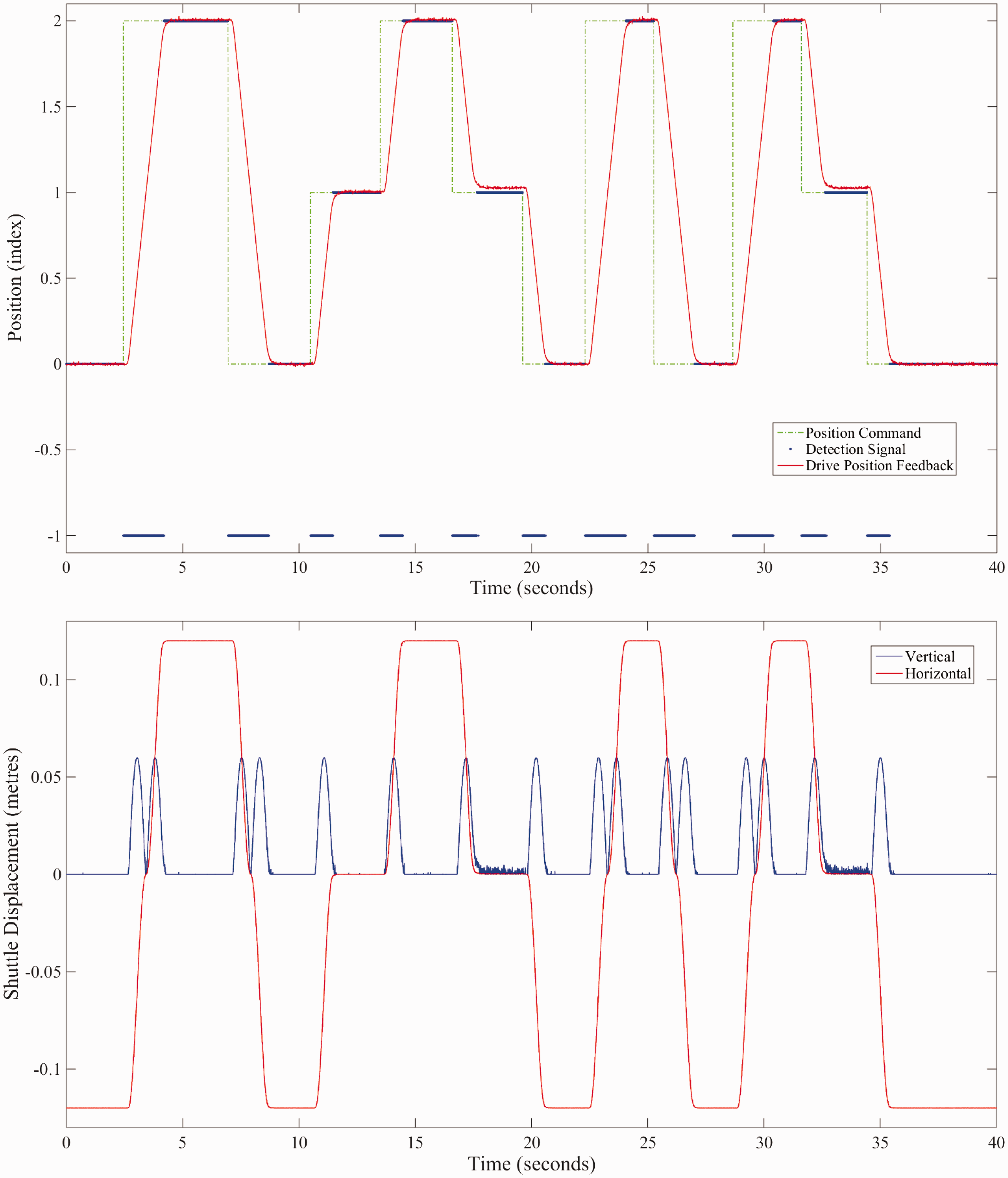
Figure 8 illustrates the comparison between the software model and rig over time, for the same sample of switch operations. It can be observed that the tuned software models presented in previous literature,
32
are a reasonable fit to the real-world data. Motor speed closely follows the simulated speed. This is to be expected as the simulated speed is also used as a basis for a speed profile to which all three motors are driven. There is a more significant error, however, in the motor current modelling. This is most noticeable in the period between rig operation, and comes from the inner current control loop amplifying sensor noise for the command signal. Sensor noise is not part of the software model, therefore the ‘at rest’ signal appears much cleaner. During periods of motion, the typical error is just over 200 mA on a 1.5 A command signal, equating to a mean model error of around 14% for the unloaded case. There is also significant error during the motor inrush period, though the inrush is to be eradicated in future implementations with a soft-start controller. Parameters have been built into the software model such that an actuator bank at full-scale and under a range of load cases can be simulated, as presented in Ebinger and Wright.
31
This will also be used in future work developing a full-scale implementation.
Plots from Repoint model validation process, for same set of runs as Figure 7. Top: Motor speed and modelled motor speed vs time. The modelled motor speed is also used as a command signal to the physical motor. Bottom: Modelled motor current, actual motor current and residual error, with moving average. There is a considerable level of noise on the signal, but residual error during periods of motion is around 10–15%.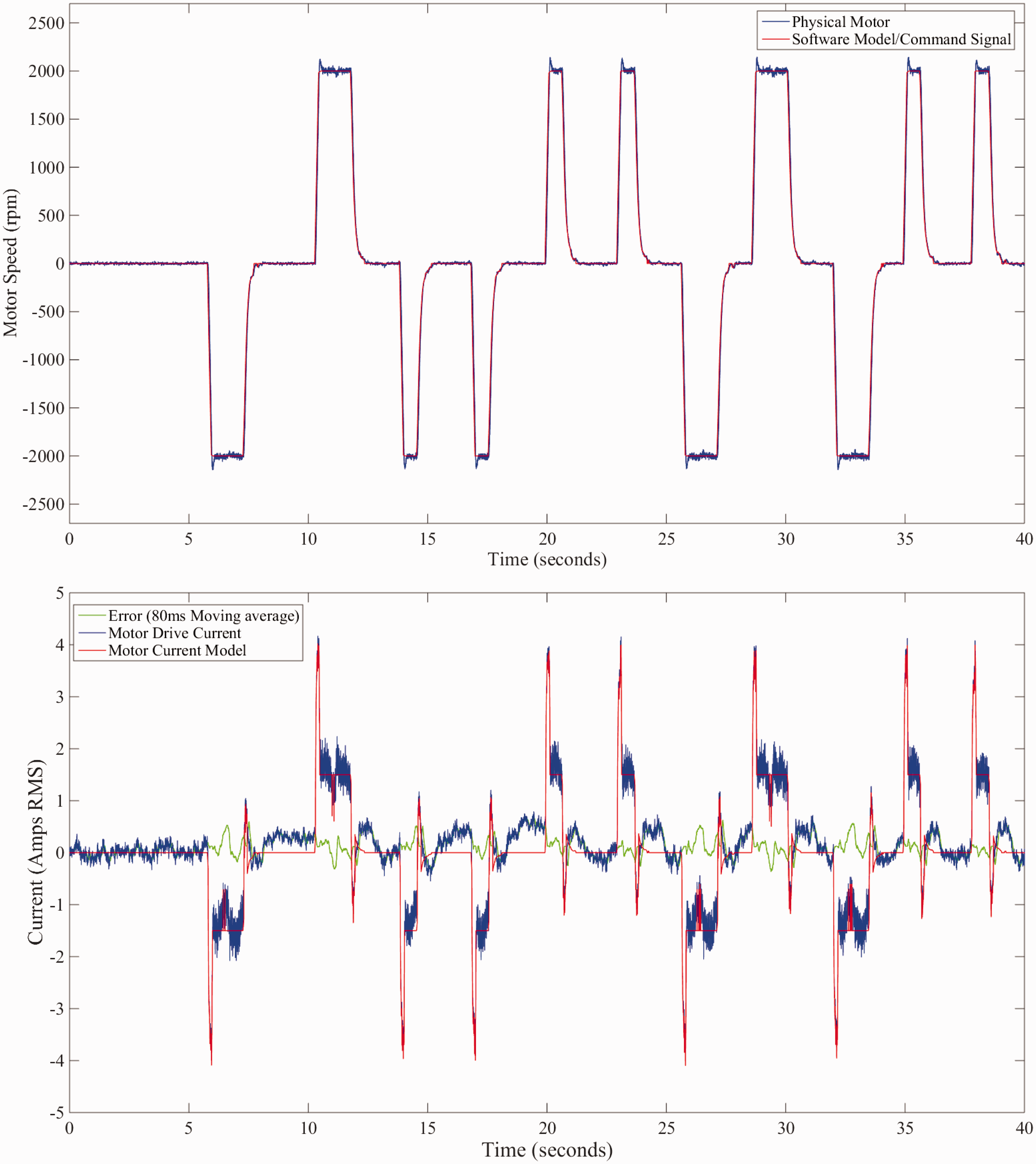
Conclusion
This paper has presented the background and context to railway track switching, including how track switches can limit the performance of rail networks. These limitations come about as track switch designs have evolved over time to fulfil a particular purpose, meaning they may not be optimised to provide the kind of performance a modern railway network requires. Specifically, the paper has established the formal requirements of track switching solutions, and presented the argument that traditional solutions do not meet all of these requirements. A shortlist of possible design options was generated alongside a non-exhaustive range of design options generated by a cross-industry panel. These options were then reviewed and ranked, with several of the options being combined to create a novel solution to the track switching problem. This novel solution, presented in academic literature for the first time, has been termed the ‘Repoint’ solution, and is described in mechanical detail, including how it satisfies the functional requirements. A scale demonstrator implementation of this solution has been constructed in a laboratory as a first step towards deployment.
Future work
The design has now been taken to a concept demonstrator phase, therefore the most obvious piece of follow-on work is to build a prototype upon a functioning railway and test – both the operation of the switch, and with the passage of traffic. Suggested, but non-exhaustive, areas of related research are as follows:
Further modelling of the capacity improvements brought about by a Repoint installation in real-world scenarios. Further investigation into, and modelling of, the reliability and maintainability improvements brought about by Repoint installations, singly or across a network. A full, formal fault tree analysis (FTA) of any proposed design. Investigation into wear and fatigue of the bending rails and part-section rail ends with a range of use cases. Investigation into other promising ideas from the concept down-selection phase, including ideas which were rejected for political or standards reasons, such as VBS.
Footnotes
Acknowledgements
The authors wish to extend their gratitude to the staff of industrial and academic organisations who have contributed their time, experience and ideas to the Repoint study, particularly in the focus group sessions. Non-exclusively, and in no particular order, the staff of: RSSB (Rail Safety and Standards Board), Network Rail, TfL (Transport for London)/London Underground, ATOC (Association of Train Operating Companies), Tracsis PLC, NTEC (Nottingham Transport Engineering Centre), Interfleet Technology Ltd, Andy Foan Ltd, Progress Rail Services (UK) Ltd, DfT (Department for Transport), and ORR (Office of Rail Regulation).
Declaration of Conflicting Interests
The author(s) declared no potential conflicts of interest with respect to the research, authorship, and/or publication of this article.
Funding
The author(s) disclosed receipt of the following financial support for the research, authorship, and/or publication of this article: The authors acknowledge the financial support provided by the United Kingdom EPSRC (Engineering and Physical Sciences Research Council) and the United Kingdom RSSB (Railway Safety and Standards Board) in grant number EP/I010823/1, for the project REPOINT: Redundantly engineered points for enhanced reliability and capacity of railway track switching. The authors also acknowledge the support of the UKs Future Railway, for providing funding towards concept demonstrator design and construction (![]() ).
).