
Abstract
Hydraulic interconnected suspension (HIS) systems represent a burgeoning technology in the automotive industry, notably due to their abilities to reconcile the well-known trade-off between ride comfort and handling performance. Numerous design possibilities for HIS systems exist, considering various hydraulic components (such as orifices, accumulators, and pipelines) and their topological connections. At present there is a lack of a systematic design approach for such systems. Traditional design approaches focus on making piecemeal modifications to existing designs, neglecting a substantial catalogue of fundamentally different and transformative schemes. Consequently, significant potential performance enhancements remain untapped. To address this limitation, this paper proposes a novel systematic design approach for HIS systems, which enables a wide range of design possibilities to be explored, and an optimal configuration to be identified. The efficacy of the methodology is demonstrated via a case study. Given a predefined design complexity, a beneficial single-axle HIS system is constructed, which can achieve a 15.6% ride comfort performance improvement while maintaining roll-control performance compared with the traditional system.
Keywords
Introduction
In automotive vehicles, suspension requirements for handling and ride comfort are inherently conflicting. 1 Hydraulic interconnected suspension (HIS) systems have shown superior capability in mitigating this trade-off compared to conventional standalone suspensions.2–4 An interconnected suspension system, by definition, generates a force at one wheel station in response to a displacement at another wheel station. 5 HIS systems contain either single or double-acting hydraulic piston cylinders, which replace conventional shock absorbers. Hydraulic circuits interconnect the fluid chambers within these cylinders, incorporating components such as orifices, gas-filled accumulators, and pipelines. These circuits enable tailored force distribution across suspension modes (roll, bounce, pitch, warp), allowing independent optimisation of vehicle dynamics. 5 Figure 1(a) illustrates a schematic representation of a conventional single-axle HIS system. 6 Single-axle HIS systems, such as those connecting right and left suspensions, are primarily employed to enhance roll stiffness and bounce mode control, improving stability during cornering without compromising ride comfort. Cross-axle HIS designs interconnect both right/left and front/rear suspension units, enabling simultaneous enhancements in roll and pitch stiffness. This configuration improves handling, braking stability, and overall body control. A well-known example is the Kinetic H2 system, which employs a fully cross-linked hydraulic network to deliver active-like roll and pitch control while remaining a passive system.2,6 Traditional HIS systems are passive devices, however, more recently, research efforts have been applied to develop advanced HIS systems using active strategies.7,8 Although active suspension systems are increasingly favoured for their ability to dynamically alter suspension characteristics in real time and further improve ride–handling balance, passive systems remain predominant in production vehicles due to their simpler architecture, lower energy demands, and proven long-term reliability. To this end, alternative passive HIS designs with enhanced performance characteristics are highly valuable to the industry. 2
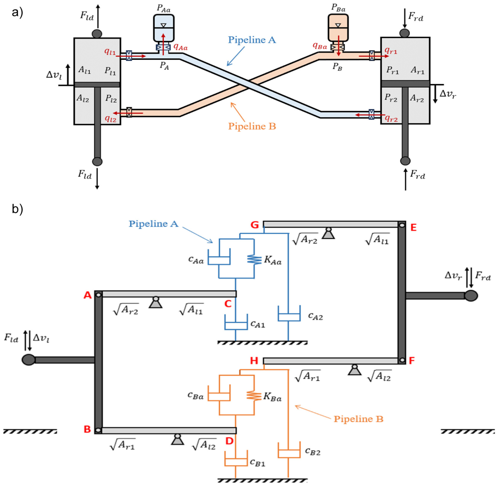
(a) A conventional single-axle HIS system, defined in the roll mode and (b) an equivalent unified mechanical network for the conventional single-axle HIS system (online version available in colour).
To further the performance of passive HIS systems, efforts have been applied to design the hydraulic circuit for both single-axle HIS configurations and cross-axle HIS designs. For instance, adding accumulators, 9 integrating air springs, 10 or testing fixed circuit variants. 11 While beneficial, these approaches explore only a narrow design space, overlooking fundamentally different configurations that could offer greater performance gains. Rather than focusing on piecemeal modifications to existing devices, network-synthesis-based approaches, such as the structure-immittance approach, 12 offer the opportunity to explore entirely new and distinct designs, in network representation. The structure-immittance approach enables the derivation of all possible series-parallel network configurations for a specified level of complexity (component type and number). 12 By using such techniques, researchers have identified optimal network-represented vibration absorber properties across various engineering fields, including automotive,13,14 railway, 15 civil engineering, 16 and wind energy sectors 17 ; these absorber properties showcase significant theoretical performance improvements compared to the best traditional designs. Li et al. 18 extended this concept to multi-domain systems by mapping physical absorbers to equivalent mechanical networks and applying network synthesis to find optimal properties, 12 later realised with physical multidomain components.
Despite a strong potential in performance improvement, it is challenging to apply the multi-domain synthesis approach in reference. 18 for the design of HIS systems. Specifically, the challenge lies in the need to develop an equivalent unifying mechanical network for the system. Naturally, HIS systems form a multi-port hydraulic network, and obtaining a dual equivalent mechanical network 19 which is a prerequisite for reference. 18 is extremely challenging since there is a lack of an existing approach which can obtain the dual of a multiport network.
To address this challenge, this paper introduces a novel design methodology for HIS systems that enables systematic exploration of a broad design space and identification of optimal configurations. Unlike previous approaches that require conversion to the mechanical domain, the proposed methodology models HIS systems directly as multi-port hydraulic networks. Network-synthesis-based techniques (e.g. structure–immittance approach) are then applied to enumerate all feasible topologies for a specified complexity. 12 The optimal network properties derived from this process are then mapped to physical hydraulic components, enabling the realisation of HIS architectures that extend beyond conventional designs. The methodology’s effectiveness is demonstrated through a single-axle HIS case study in this work. It is worth noting that the proposed methodology is also applicable to cross-axle configurations, including systems such as the Kinetic H2.
The remainder of this paper is structured as follows: Section ‘Design methodology overview’ outlines the proposed methodology. A case study demonstrating the effectiveness of this methodology is presented in Sections ‘Design problem formulation’, ‘Benchmark network development’, ‘Optimal network-represented HIS’, and ‘Physical device realisation’, whereby the accumulator branch of a single-axle HIS system is optimally designed. Finally, conclusions are drawn in Section ‘Conclusion’.
Design methodology overview
The existing multi-domain synthesis approach is difficult to implement for the design of HIS systems. Subsection ‘Challenge of developing an equivalent mechanical network’ will discuss the primary challenge associated with its application, while Subsection ‘Methodology overview’ will outline a novel HIS design approach, using a structured framework.
Challenge of developing an equivalent mechanical network
A conventional single-axle HIS system is displayed in Figure 1(a). Fluid flows, instantaneous system pressures, and cross-sectional chamber areas are denoted by the variables
The existing multidomain synthesis approach begins by establishing an equivalent unifying mechanical network for a conventional multidomain absorber.
18
According to Li et al.,
18
the conventional single-axle HIS system, shown in Figure 1(a), must first be translated into an equivalent hydraulic network, and then dually transformed into an equivalent mechanical counterpart.
19
The developed hydraulic network for pipeline A can be found in Figure 2(b), and it can be seen that the network has three-terminals (
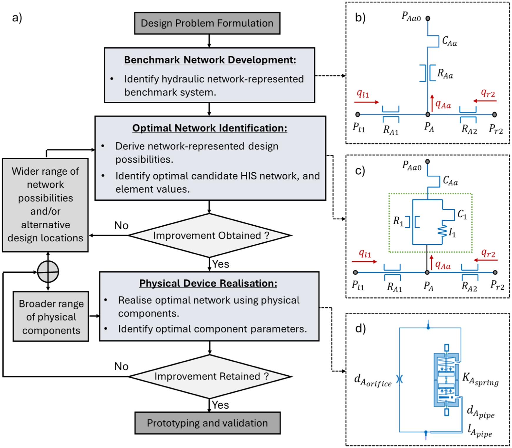
(a) A framework summarising the proposed methodology for the design of HIS systems, (b) a three-terminal network representation of pipeline A of a conventional single-axle HIS system, (c) pipeline A of an identified optimal candidate HIS network, and (d) physical device realisation. Note that (b–d) are specific for the case study demonstrated in this paper.
Following Li et al.,
18
an equivalent unified mechanical network for the conventional HIS can be developed as shown in Figure 1(b). For detailed derivation, readers are referred to the Supplementary Material.
20
The network consists of two pairs of lever arms and two three-terminal mechanical networks. The use of lever arms is to account for variations between the cross-sectional areas of the chambers, for the left and right single-rod piston cylinders (i.e.
The endpoints C, G, and the ground, are interconnected by a three-terminal mechanical network, which represents pipeline A of the conventional single-axle HIS, and the endpoints D, H, and the ground, are interconnected by another three-terminal mechanical network, which represents pipeline B. Such mechanical network is the dual of its hydraulic counterpart, illustrated in Figure 1(a). The properties
While the equivalent unified mechanical network for the conventional single-axle HIS can be obtained, the dual transformation process introduces inherent complexities, particularly due to the inclusion of lever arm pairs. These complexities are anticipated to escalate when addressing the mechanical dual of a non-mechanical multi-port network with an increased number of terminals. For instance, in the case of the Kinetic H2 system, a conventional four-wheel HIS configuration, the hydraulic network (representing a single pipeline) features five terminals. 21 To date, no equivalent unified mechanical network for this system has been identified, primarily because no existing method can reliably derive the dual of a multi-port network.
With the introduction of the inerter, a two-terminal device in which the forces applied at the terminals are proportional to the relative accelerations between them, the mechanical-electrical-hydraulic analogy becomes complete. 22 This comprehensive analogy facilitates the application of network-synthesis-based techniques across such domains. As a result, it becomes more practical to develop a network for a complex system and apply network-synthesis-based techniques within the domain that predominates its operation. Accordingly, the design approach proposed in this paper will exclusively utilise the hydraulic domain.
Methodology overview
This section presents an overview of the proposed methodology for the design of HIS systems, outlined as a framework in Figure 2(a). The methodology begins by mathematically formulating a design problem. This involves developing a vehicle model, termed ‘host structure’, and defining its operational scenarios. Based on the identified operational scenarios, an appropriate objective function and constraint(s) are selected to facilitate the optimal design of a HIS. Additionally, a physical model of a conventional HIS system, referred to as the ‘physical benchmark’, is established.
Upon formulating the design problem, a beneficial physical HIS system can be constructed in three key steps, outlined as follows:
(1) Benchmark network development
In this step, the physical benchmark is transformed into an equivalent multi-port hydraulic network configuration. During this transformation, physical components of the HIS system are represented using hydraulic modelling elements, and their topological arrangements are carefully accounted for. These modelling elements capture the essential linear properties of the physical components, in an idealised manner. 23 The resulting hydraulic network serves as a benchmark and is referred to as the ‘network-represented benchmark’. This benchmark network will allow a wide range of network-represented design possibilities to be explored in step 2.
For the case study detailed in this paper, Figure 2(b) illustrates the three-terminal equivalent hydraulic network for pipeline A of the physical benchmark, which is a single-axle HIS system. Linear hydraulic resistance elements (
(2) Optimal network identification
In this step, an optimal network-represented HIS configuration is determined. Initially, a full set of hydraulic network-represented design possibilities are generated for a pre-determined complexity, using an existing network synthesis technique, such as the structure-immittance approach. 12 The pre-determined complexity is a design choice. Next, a decision is made regarding which part of the network/system will be designed. Once this choice is made, the generated network possibilities will replace the corresponding original section in the network-represented benchmark configuration. These integrated networks are termed ‘candidate HIS networks’. Each candidate HIS network is subsequently incorporated into the host structure model. An optimisation algorithm is then employed to determine the optimal network in terms of topology and element values, assessed against the selected cost function and constraints.
For the case study detailed in this paper, a full set of series-parallel hydraulic network layouts consisting of one inertance, one resistance, and one compliance element are enumerated based on the so-called generic networks shown in Figure 7(a). The focus for this case study is to design the accumulator inlet, that is, modify
(3) Physical device realisation
In this step, the optimal network properties identified in step 2 are realised using physical components, such as orifices and pipelines. The topological arrangement of the selected physical components remains consistent with the modelling elements in the optimal network. However, due to inherent non-linearities, the behaviour of the physical device will inevitably differ from its optimal network representation. This necessitates further modelling and optimisation. By integrating the model representing the physical device with the host structure, key design parameters are optimised according to the objective function and constraints, resulting in a physical HIS solution.
For the case study detailed in this paper, different physical components are selected to realise the linear hydraulic inertance, resistance, and compliance modelling elements of the identified optimal network configuration. The selected components are implemented within the multi-physics modelling software AMEsim, as shown in Figure 2(d). 24 Parameter definitions for the variables in Figure 2(d), can be found in Section ‘Physical realisation development’.
It should be noted that within this framework, there exists two conditional loops: (1) If step 2 does not yield satisfactory performance improvements, a wider range of network-represented design possibilities should be explored, that is, considering an alternative complexity, and/or alternative design locations; (2) Following step 3, if the performance of the physical HIS system is not satisfactory, a broader selection of physical hydraulic components should be considered. Alternatively, one may revert to step 2. The physical HIS system is deemed ready for prototyping and subsequent performance evaluation only upon completion of these steps.
Design problem formulation
In this section, the design problem for the case study is formulated. Firstly, a linear four-degrees-of-freedom (4-DOF) roll-plane half-car model, compatible with a single-axle HIS system, is developed. Next, an appropriate objective function and constraint(s) is chosen to quantitatively measure the vehicle’s dynamic performance under different operational scenarios. Subsequently, a multiphysics model of a conventional single-axle HIS system is constructed.
Development of a 4DOF half-car model
A linear 4DOF roll-plane half-car model, which exhibits left-right symmetry, is depicted in Figure 3. The model consists of two unsprung masses,
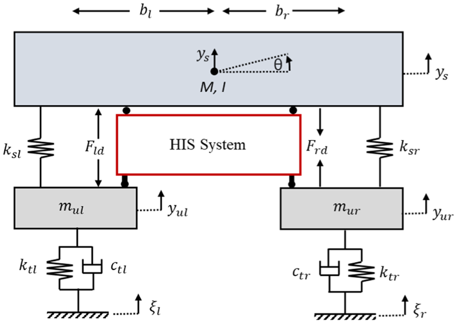
Schematic diagram of a linear 4DOF roll-plane half car model integrated with a single-axle HIS system.
The equations of motion describing the half-car model in the Laplace domain, can be expressed as follows:
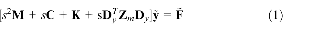
where
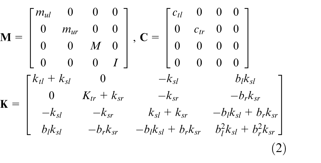
The vector

where
Optimisation cost function and constraints
By implementing the equations of motion for the HIS-integrated half-car model, as detailed in subsection ‘Development of a 4DOF half-car model’, in MATLAB, 26 the effects of various HIS systems on vehicle dynamics can be analysed under diverse operational conditions. In this case study, ride-handling dynamics are investigated. The design target is chosen to improve the ride-comfort performance, without compromising the handling performance, of a conventional single-axle HIS system. To enable an analysis of ride-handling dynamics, a single-wheel bump input and a fishhook manoeuvre scenario are selected as the operational conditions for the vehicle, respectively.27–30
The single-wheel bump input is simulated in MATLAB, characterised by a sinusoidal wave spanning 180°.
26
The bump features dimensions

where

where,
The fishhook manoeuvre is selected to assess the vehicle’s roll control performance. A torque input is generated based on the steering angle input in reference, 31 and it is applied on the roll DOF of the HIS-integrated half-car model, in MATLAB. 26 A constraint is applied to the peak roll angle of the vehicle’s sprung mass during this operational scenario, to ensure vehicle roll control. This constraint can be mathematically expressed as:

where,
Multiphysics HIS model
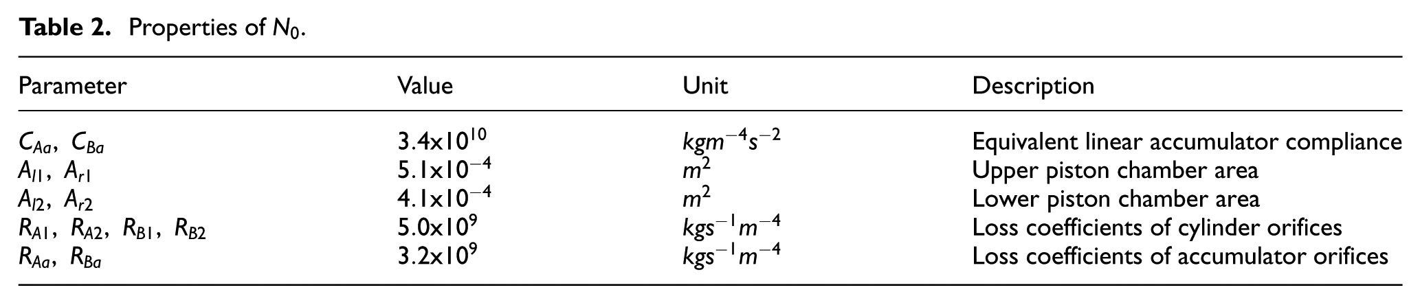
Establishing a physical benchmark system is essential for defining a reference performance, which in turn is crucial for evaluating new physical designs. In this case study, the physical benchmark system, a conventional single-axle HIS, is developed using the hydraulics library within AMEsim and in accordance with the parameters in References.24,25 The constructed physical benchmark, termed
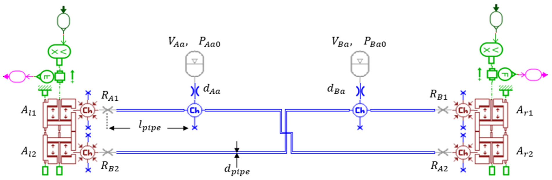
Multiphysics model of the physical benchmark HIS system,
Properties of
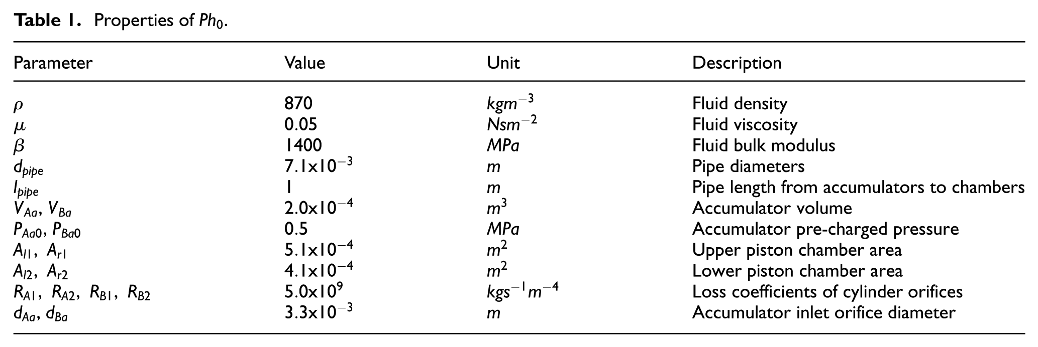
There is a notable difference between the parameters specified in reference 25 and those used in this study, which pertains to the accumulator inlet properties. In reference, 25 each linear hydraulic resistance element, representing a flow restriction in the accumulator branch, is replaced with an orifice characterised by a realistic physical property, specifically a diameter. This modification aims to achieve a more realistic analysis of the physical benchmark system. Various orifice diameters are examined, using a least squares regression polynomial fitting technique, to determine an outer diameter which can provide equivalent pressure drop and flow rate characteristics to the linear hydraulic resistance described in reference. 25 Figure 5 shows the conducted polynomial fitting. 34
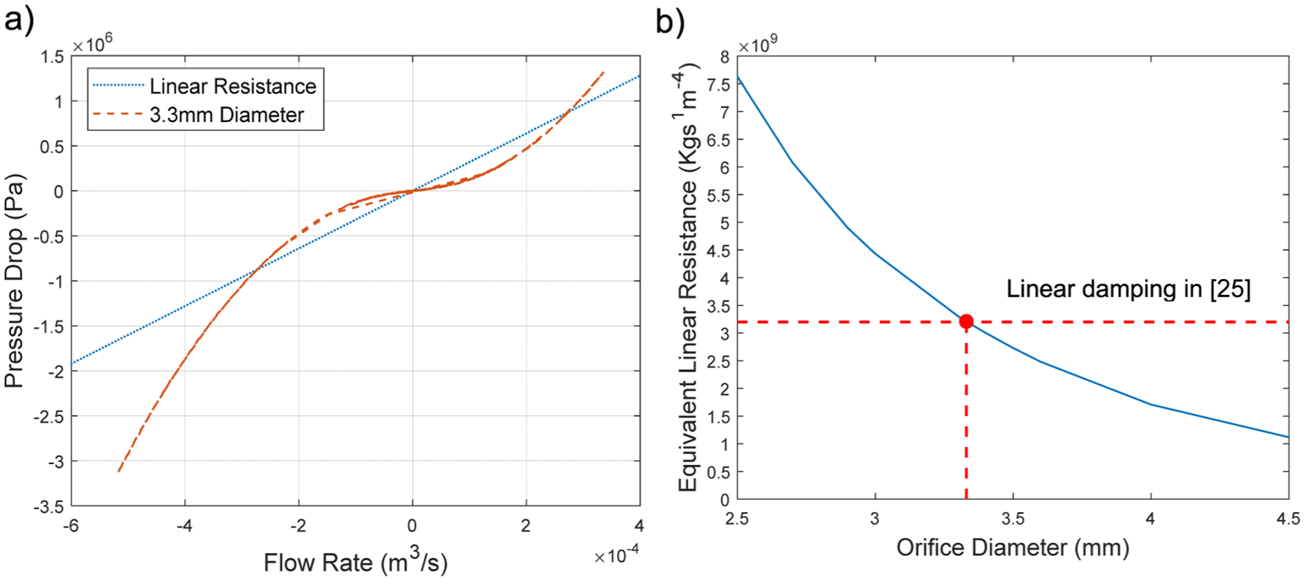
(a) Orifice diameter identified as providing equivalent linear properties and (b) relationship between different orifice diameters and their corresponding equivalent linear hydraulic resistance.
The physical benchmark is built to be compatible with MATLAB.
26
In Figure 4, the green AMEsim components represent mechanical elements, while the pink AMEsim components are sensors. These sensors facilitate the conversion of hydraulic signals from the HIS into mechanical signals compatible with the host structure model in MATLAB, and vice versa, transforming mechanical signals from the host structure into hydraulic inputs for the HIS system in AMEsim. With the physical benchmark system developed, co-simulation of the HIS-integrated half-car model in MATLAB-AMEsim is performed to establish a benchmark performance.24,26 This co-simulation is conducted under the operational scenarios defined in Section ‘Optimisation cost function and constraints’. Performance for
Benchmark network development
To apply network synthesis techniques for the design of HIS systems, it is essential to represent the physical benchmark system, as shown in Figure 4, as an equivalent hydraulic multi-port network, comprising modelling elements. In Figure 2(b), the three-terminal hydraulic network representation for pipeline A of the physical benchmark system is shown. The network contains hydraulic modelling elements
In this case study, the network representation for pipeline B is not provided; however, it would precisely mirror pipeline A as symmetry preservation is fundamental in HIS systems. By leveraging the network representations for both pipelines A and B, the network-represented benchmark system, denoted as
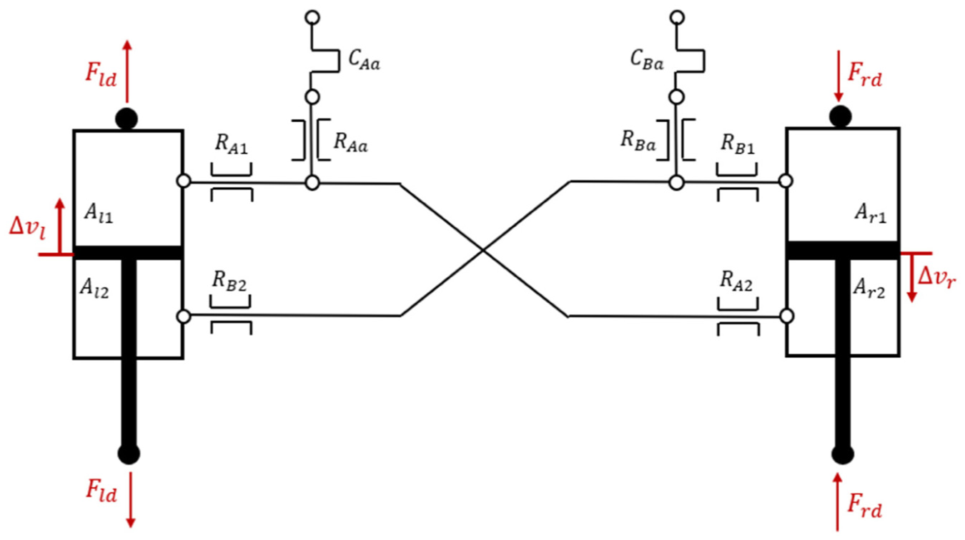
A schematic diagram of the network-represented benchmark system,
The relationship between the dynamic forces and relative velocities of

Where,
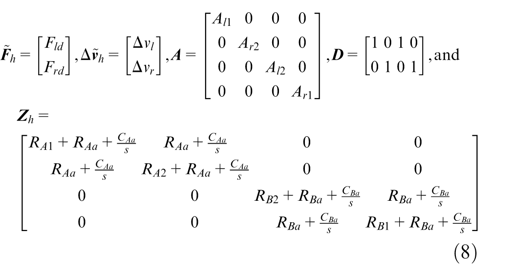
Here,

The parameter values for
Properties of
By integrating
Performance and parameter settings for the benchmark, optimised benchmark, and beneficial candidate network-represented HIS configurations.
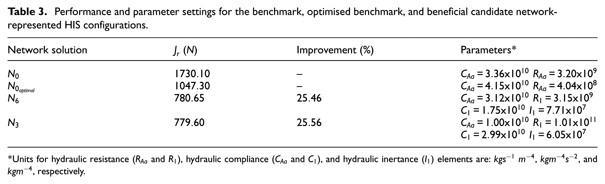
Units for hydraulic resistance (
Optimal network-represented HIS
Based on the benchmark network developed in Section ‘Benchmark network development’, a wide range of candidate HIS networks are explored. Firstly, network-represented candidate design possibilities are proposed using the structure-immittance approach. 12 These design possibilities are then individually integrated into the benchmark network, and in turn the host structure model. By performing optimisation, several beneficial network-represented designs are identified.
Candidate design possibilities
In this case study, the structure-immittance approach is employed to systematically enumerate network-represented design possibilities for the HIS system.
12
Two so-called generic networks, with a given complexity of one hydraulic inertance,
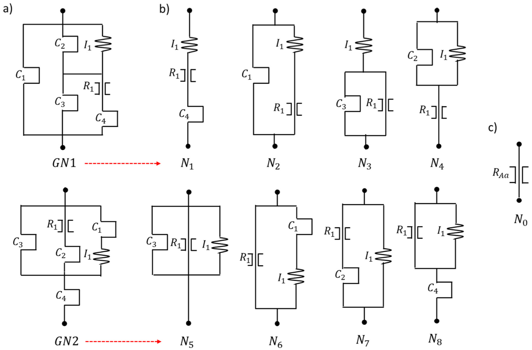
(a) Two so-called generic networks,
The accumulator branch is selected as the design focus for this case study. Specifically, each network possibility will replace the accumulator inlet damping component
Identification of beneficial network configurations
To identify the network configurations that enhance dynamic performance, the network-represented design possibilities proposed in Subsection ‘Candidate design possibilities’ are optimised. Specifically, each network possibility is substituted into the benchmark network-represented system, thereby creating candidate HIS networks. These candidate HIS networks are then integrated within the host structure model. Optimisation is conducted in MATLAB to determine the optimal set of element values that minimise the cost function
In addition to optimising the new designs, it is important to also optimise the benchmark accumulator branch (i.e.
The results indicate that network configurations
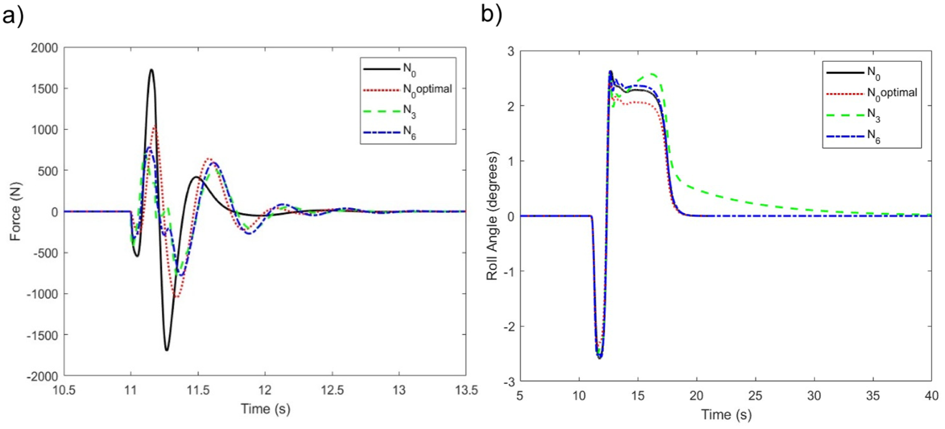
Response for the: (a) total right suspension force when subject to a single-wheel bump input and (b) sprung mass roll angle under a fishhook manoeuvre.
Physical device realisation
In this section, a physical device is constructed to realise the optimal hydraulic network configuration identified in Subsection ‘Identification of beneficial network configurations’. Upon establishment, this device is integrated into the physical benchmark HIS system, replacing each accumulator inlet orifice component. The novel physical HIS system is then unified with the host structure model, and key design parameters are optimised in accordance with the selected objective function and constraints to assess system performance.
Physical realisation development
Having identified the optimal hydraulic network configuration
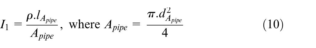
Here,
Through the use of a dual spring device, a straight pipe, and an orifice, the hydraulic network for
Physical parameter identification
It is essential to identify the parameter values for the physical components within
To ensure a fair comparison between the performance of the newly identified physical HIS system and that of the physical benchmark system, it is necessary to also optimise the components within the accumulator branch (
Performance and parameter settings for the physical benchmark, optimal physical benchmark, and the newly identified physical HIS system.
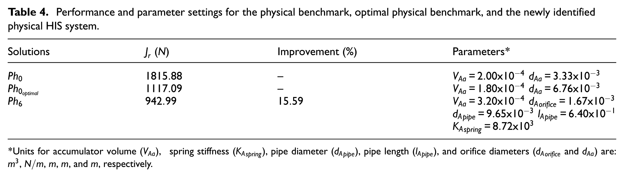
Units for accumulator volume (
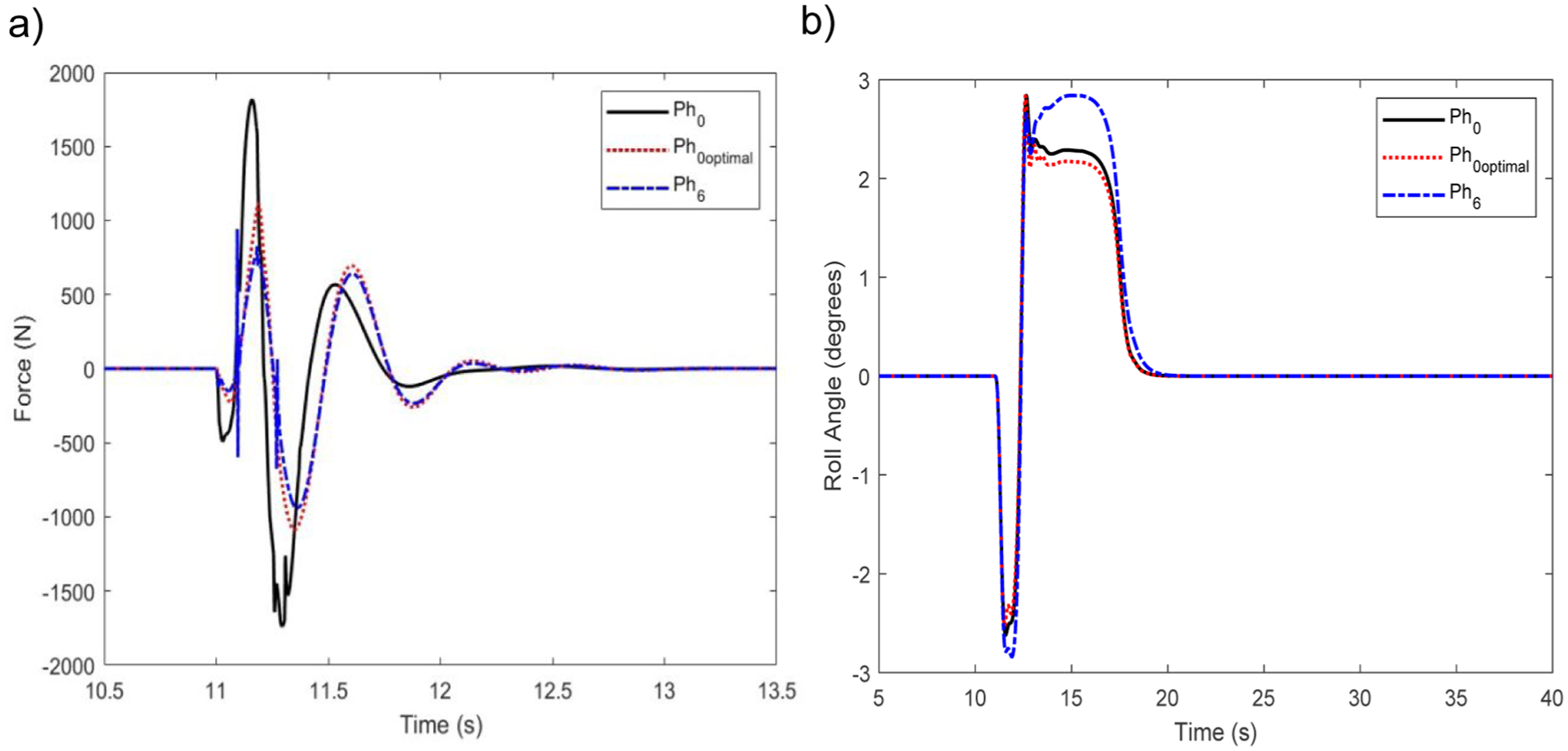
Response for the: (a) total right suspension force when subject to a single-wheel bump input and (b) sprung mass roll angle under a fishhook manoeuvre, for the physical benchmark
In addition to the cost function and constraints considered in the optimisation, it is crucial to carry out a comprehensive performance assessment of the obtained beneficial HIS design. Figure 10(a) and (b) depict the suspension travel and tyre–contact force under a single-wheel bump input, while Figure 10(c) and (d) show the corresponding responses during the fishhook manoeuvre. For brevity, only the right side of the vehicle is presented; however, both sides were analysed, and the results are consistent. Under the single-wheel bump input, no compromise in suspension travel or tyre–contact force is observed. During the fishhook manoeuvre, a slight compromise is observed; however, this deviation is minor and remains within an acceptable margin, particularly given that this study serves as a demonstration of the proposed design methodology. To further evaluate the performance of
where
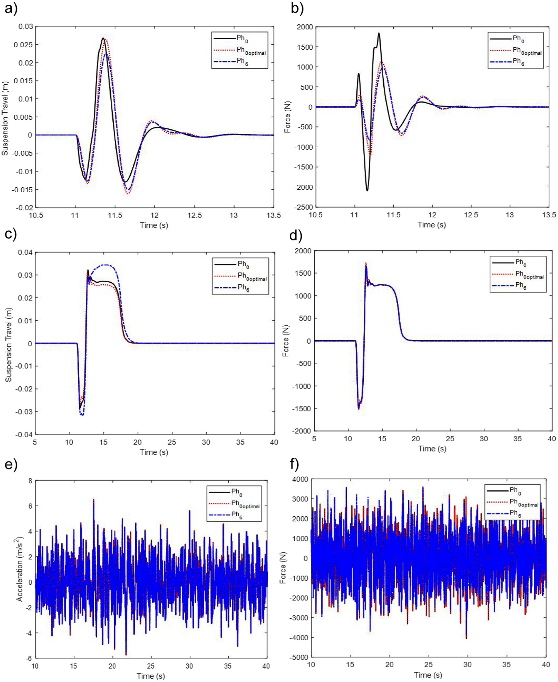
Further physical HIS system responses for: (a) right suspension travel, (b) right tyre-contact force, over a single-wheel bump input, (c) right suspension travel, (d) right tyre-contact force, during a fishhook manoeuvre input, (e) central body vertical acceleration, and (f) right tyre-contact force, during a rough road input.
Conclusion
This paper proposes a design methodology for HIS systems. The methodology firstly allows a conventional HIS system to be represented as an equivalent hydraulic multi-port network configuration. Subsequently, it enables an optimal network-represented HIS system to be identified, considering the totality of design configurations for a predetermined complexity, utilising existing network synthesis techniques. Finally, the methodology facilitates the physical realisation of a beneficial network-represented HIS system. Compared with traditional HIS design approaches which focus on making piecemeal modifications to existing configurations, the proposed methodology systematically explores a wide range of possibilities. This broadens the design scope for HIS systems, allowing significant performance benefits to be unlocked. The effectiveness of the proposed methodology is demonstrated via a case study, wherein the accumulator branch of a single-axle HIS system is designed. An optimal network represented HIS system is identified, considering a predetermined complexity of one hydraulic inertance, one hydraulic resistance, and one hydraulic compliance elements. This network representation can achieve 25.5% ride comfort performance enhancement over the conventional configuration. The optimal network-represented HIS system is constructed using physical components. Compared with the optimal conventional physical HIS system, the novel physical design can yield a 15.6% performance enhancement in ride comfort under a single wheel bump input, without compromising the roll control performance. A comprehensive performance assessment of the proposed design, compared with the optimal conventional physical HIS system, has also been carried out with no evident compromise identified. It is worth nothing that integrating a multi-objective optimisation function into the design problem formulation could further enhance overall system performance. It is also important to emphasise that this case study represents only one design example. Within the design framework the network complexity can be readily adjusted to consider a wide range of configurations, including variations in the number and types of elements. In addition, the proposed methodology can be directly applied to optimally design other components of the HIS system, such as pipes and piston-cylinder assemblies; and it can be extended to investigate more advanced HIS configurations, including cross-axle interconnection topologies for multi-axle systems and active-passive hybrid configuration.
Supplemental Material
sj-docx-1-pid-10.1177_09544070251395345 – Supplemental material for A design approach for hydraulic interconnected suspension systems
Supplemental material, sj-docx-1-pid-10.1177_09544070251395345 for A design approach for hydraulic interconnected suspension systems by Emily Nar, Duanqi Zhao, Yuan Li, Jason Zheng Jiang, Monzer Al Sakka, Branislav Titurus and Simon Neild in Proceedings of the Institution of Mechanical Engineers, Part D: Journal of Automobile Engineering
Footnotes
Appendix
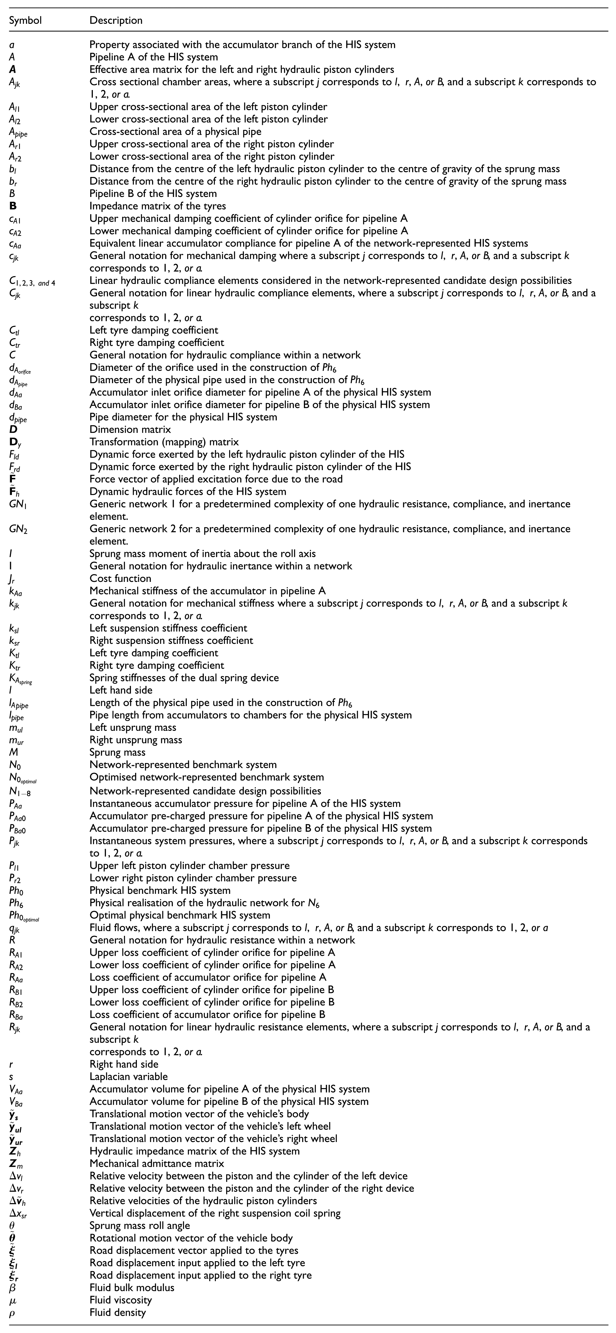
| Symbol | Description |
|---|---|
| Property associated with the accumulator branch of the HIS system | |
| Pipeline A of the HIS system | |
| Effective area matrix for the left and right hydraulic piston cylinders | |
| Cross sectional chamber areas, where a subscript corresponds to , , or , and a subscript corresponds to , , or . | |
| Upper cross-sectional area of the left piston cylinder | |
| Lower cross-sectional area of the left piston cylinder | |
| Cross-sectional area of a physical pipe | |
| Upper cross-sectional area of the right piston cylinder | |
| Lower cross-sectional area of the right piston cylinder | |
| Distance from the centre of the left hydraulic piston cylinder to the centre of gravity of the sprung mass | |
| Distance from the centre of the right hydraulic piston cylinder to the centre of gravity of the sprung mass | |
| Pipeline B of the HIS system | |
| Impedance matrix of the tyres | |
| Upper mechanical damping coefficient of cylinder orifice for pipeline A | |
| Lower mechanical damping coefficient of cylinder orifice for pipeline A | |
| Equivalent linear accumulator compliance for pipeline A of the network-represented HIS systems | |
| General notation for mechanical damping where a subscript corresponds to , , or , and a subscript corresponds to , , or . | |
| Linear hydraulic compliance elements considered in the network-represented candidate design possibilities | |
| General notation for linear hydraulic compliance elements, where a subscript corresponds to , , or , and a subscript corresponds to , , or . | |
| Left tyre damping coefficient | |
| Right tyre damping coefficient | |
| General notation for hydraulic compliance within a network | |
| Diameter of the orifice used in the construction of | |
| Diameter of the physical pipe used in the construction of | |
| Accumulator inlet orifice diameter for pipeline A of the physical HIS system | |
| Accumulator inlet orifice diameter for pipeline B of the physical HIS system | |
| Pipe diameter for the physical HIS system | |
| Dimension matrix | |
| Transformation (mapping) matrix | |
| Dynamic force exerted by the left hydraulic piston cylinder of the HIS | |
| Dynamic force exerted by the right hydraulic piston cylinder of the HIS | |
| Force vector of applied excitation force due to the road | |
| Dynamic hydraulic forces of the HIS system | |
| Generic network 1 for a predetermined complexity of one hydraulic resistance, compliance, and inertance element. | |
| Generic network 2 for a predetermined complexity of one hydraulic resistance, compliance, and inertance element. | |
| Sprung mass moment of inertia about the roll axis | |
| I | General notation for hydraulic inertance within a network |
| Cost function | |
| Mechanical stiffness of the accumulator in pipeline A | |
| General notation for mechanical stiffness where a subscript corresponds to , , or , and a subscript corresponds to , , or . | |
| Left suspension stiffness coefficient | |
| Right suspension stiffness coefficient | |
| Left tyre damping coefficient | |
| Right tyre damping coefficient | |
| Spring stiffnesses of the dual spring device | |
| Left hand side | |
| Length of the physical pipe used in the construction of | |
| Pipe length from accumulators to chambers for the physical HIS system | |
| Left unsprung mass | |
| Right unsprung mass | |
| Sprung mass | |
| Network-represented benchmark system | |
| Optimised network-represented benchmark system | |
| Network-represented candidate design possibilities | |
| Instantaneous accumulator pressure for pipeline A of the HIS system | |
| Accumulator pre-charged pressure for pipeline A of the physical HIS system | |
| Accumulator pre-charged pressure for pipeline B of the physical HIS system | |
| Instantaneous system pressures, where a subscript corresponds to , , or , and a subscript correspondsto , , or . | |
| Upper left piston cylinder chamber pressure | |
| Lower right piston cylinder chamber pressure | |
| Physical benchmark HIS system | |
| Physical realisation of the hydraulic network for | |
| Optimal physical benchmark HIS system | |
| Fluid flows, where a subscript corresponds to , , or , and a subscript corresponds to , , or | |
| General notation for hydraulic resistance within a network | |
| Upper loss coefficient of cylinder orifice for pipeline A | |
| Lower loss coefficient of cylinder orifice for pipeline A | |
| Loss coefficient of accumulator orifice for pipeline A | |
| Upper loss coefficient of cylinder orifice for pipeline B | |
| Lower loss coefficient of cylinder orifice for pipeline B | |
| Loss coefficient of accumulator orifice for pipeline B | |
| General notation for linear hydraulic resistance elements, where a subscript corresponds to , , or , and a subscript corresponds to , , or . | |
| Right hand side | |
| Laplacian variable | |
| Accumulator volume for pipeline A of the physical HIS system | |
| Accumulator volume for pipeline B of the physical HIS system | |
| Translational motion vector of the vehicle’s body | |
| Translational motion vector of the vehicle’s left wheel | |
| Translational motion vector of the vehicle’s right wheel | |
| Hydraulic impedance matrix of the HIS system | |
| Mechanical admittance matrix | |
| Relative velocity between the piston and the cylinder of the left device | |
| Relative velocity between the piston and the cylinder of the right device | |
| Relative velocities of the hydraulic piston cylinders | |
| Vertical displacement of the right suspension coil spring | |
| Sprung mass roll angle | |
| Rotational motion vector of the vehicle body | |
| Road displacement vector applied to the tyres | |
| Road displacement input applied to the left tyre | |
| Road displacement input applied to the right tyre | |
| Fluid bulk modulus | |
| Fluid viscosity | |
| Fluid density |
Funding
The authors disclosed receipt of the following financial support for the research, authorship, and/or publication of this article: This research was supported by Engineering and Physical Science Research Council (Grant no: EP/T016485/1).
Declaration of conflicting interests
The authors declared no potential conflicts of interest with respect to the research, authorship, and/or publication of this article.
Supplementary material
Supplementary material for this article is available online.
References
Supplementary Material
Please find the following supplemental material available below.
For Open Access articles published under a Creative Commons License, all supplemental material carries the same license as the article it is associated with.
For non-Open Access articles published, all supplemental material carries a non-exclusive license, and permission requests for re-use of supplemental material or any part of supplemental material shall be sent directly to the copyright owner as specified in the copyright notice associated with the article.