
Abstract
Lateral vehicle dynamics control is important for autonomous driving. This paper presents a data-driven design of model-referenced model-free control (DD-MR-MFC) based on an ultra-local model for vehicle yaw rate control. The characteristics of lateral vehicle dynamics systems depend on vehicle velocities and weights. For this system, fixed proportional–integral–derivative (PID) controllers cannot provide the desired control performance. Additionally, although model-based control can be applied to lateral vehicle dynamics, the modeling process is time-consuming. To efficiently design controllers that can realize the desired performance, we adopt a model-free approach. In this study, the control law of practical MR-MFC is derived by extending the traditional MFC based on an ultra-local model and using a data-driven design method. The MFC approach can be applied to nonlinear systems with few parameters, and the data-driven method provides optimized parameters from single-experiment time-series data without the need for repeated experiments and system model to be controlled. Additionally, the processing cost is considerably low because the controller parameter can be obtained using least-square methods. The effectiveness of the proposed method is verified using a multibody vehicle simulator. The yaw rate tracking performance is examined under different velocities and loads. Results showed that the root-mean-square error of the proposed method is approximately 1/100th of that when using a fixed PID controller optimized using a data-driven method.
Keywords
Introduction
Vehicle yaw rate control is important for autonomous driving. The target yaw rate is calculated for reducing the tracking error between the actual and target paths of an automated driving vehicle. A yaw rate controller calculates the steering angle as a control input signal for reducing the tracking error between the yaw rate and its target value. The desired yaw rate response enables desired path planning1–3 because path-tracking control is converted into yaw rate control. 4 The popular conventional methods employ proportional–integral–derivative (PID) control.5,6 PID control is popular in industry owing to its simplicity7,8; however, when the vehicle velocity varies, a fixed PID controller cannot realize the desired yaw rate response 9 because the lateral dynamics of the vehicle system become time-dependent. 10 A variable vehicle velocity changes the cut-off frequency and the direct current (DC) gain of lateral dynamics. These time-variant properties of the vehicle deteriorate the control performance of normal PID control. We can adopt model-based approaches, such as model predictive control,11,12 sliding mode control, 13 and robust gain-scheduled control. 14 However, controller performance is dependent on modeling accuracy. Additionally, it may be difficult to build accurate models for industrial systems.
In the past decade, model-free control (MFC) or data-driven control that does not need a plant model has garnered attention because this control can simplify the process of system identification and can be easily used. First, we describe MFC. Many types of MFC have been explored, including MFC based on ultra-local models, 15 model-free adaptive control, 16 controller parameter tuning for vibration control, 17 PID tuning via simultaneous perturbation stochastic approximation, 18 intelligent PID control for Type-1 diabetes, 19 and model-free adaptive iterative learning control for robustness and event-triggered systems.20,21 Among the numerous types of MFC, we focus on an MFC based on an ultra-local model 15 because it can be applied to nonlinear systems despite its simple controller. This control law is called MFC or intelligent PID control.15,22 MFC can achieve the desired control response even when the controlled objects exhibit nonlinearity and time-variant properties. Such MFC is efficient because it involves few tunable parameters. For industrial systems, it is crucial to maintain a small number of parameters; therefore, MFC has been widely studied.1,23–25 However, efficient MFC performance cannot be achieved without optimizing the MFC parameters. Next, we describe data-driven control. Various types of data-driven control have been proposed. 26 In this study, we considered data-driven tuning. In particular, virtual reference feedback tuning (VRFT)27–29 is well-known among the data-driven parameter tuning methods. VRFT considers the model-referenced (MR) problem and allows tuning the controller parameters using single-experiment time-series data without modeling the system. VRFT has been widely studied with regard to its applications in multi-input–multi-output systems,30,31 linear parameter-varying systems, 32 sparse gain–scheduled control, 33 model-free controllers,34,35 and look-up table type controllers. 36 Additionally, VRFT has been used in industrial systems such as vehicle lateral control, 9 bicycle control, 37 internal-combustion engines, 38 and clutch actuators. 39
In this paper, we propose a data-driven MR MFC (DD-MR-MFC) design method for vehicle yaw rate control. The proposed method combines the controller structure of the MR MFC (MR-MFC) and data-driven design method based on the VRFT framework. Practical MR-MFC is realized by extending the standard MFC to realize model matching for a vehicle system. We demonstrate that the traditional MFC is not suitable for the MR problem and derive MR-MFC that contains feedback and estimation terms. The estimation term of the traditional MFC adopts algebraic identification techniques that provide an accurate estimate but incur high calculation cost. Thus, as a practical solution to this issue, we adopt low-pass filters in the proposed method. When accurate estimation is possible, the feedback controller can be uniquely and analytically determined. In practice, an estimation error may arise because of the phase delay caused by the filter. Thus, the MR-MFC parameters should be tuned; accordingly, we adopt the VRFT framework for the data-driven method. The desired yaw rate control, which depends on vehicle velocity, can be achieved by introducing practical MR-MFC that can be designed based on single-experiment time-series data by introducing data-driven tuning.
The effectiveness of the proposed method (DD-MR-MFC) is verified using multibody vehicle (truck) simulators to consider various vehicle velocities and vehicle weights. Additionally, the performance of the proposed method is compared with the performances of other controllers, such as the standard PID tuned by VRFT and MR-MFC tuned by an analytical scheme. Simulation results showed that the proposed method provides the best tracking performance for the yaw rate and that its parameters can be designed using the proposed data-driven method. The contributions in this study can be summarized as follows:
MR-MFC is introduced to achieve the desired tracking performance. The analytical tuning scheme is derived by assuming ideal estimation.
The proposed DD-MR-MFC method is built on the VRFT framework without assuming ideal estimation. In this method, the design parameters of practical MR-MFC are directly optimized from data without a system model.
DD-MR-MFC method is applied to lateral vehicle dynamics control using multibody vehicle (truck) simulators for examining its performance under various vehicle velocities and weights. Results show that the proposed method provides the desired control performance.
The remainder of this paper is structured as follows. Section “Problem formulation” presents the problem formulation. Section “Controller structure” describes the traditional MFC and proposed practical MF-MFC. Section “Data-driven design for MR-MFC” explains the data-driven tuning method for practical MR-MFC. The numerical simulation results are presented in Section “Simulation verification.” Finally, Section “Conclusion” concludes this paper.
[Notation] To enhance readability, we denote the output time signal y(t) of G(s) relative to the input time signal u(t) as y = G(s)u and the time-derivative signal
Problem formulation
We explored MR yaw rate control. Figure 1 provides an overview of the system configuration for yaw rate control. Figure 1(a) shows a system of a front-wheel steering vehicle. In the figure,
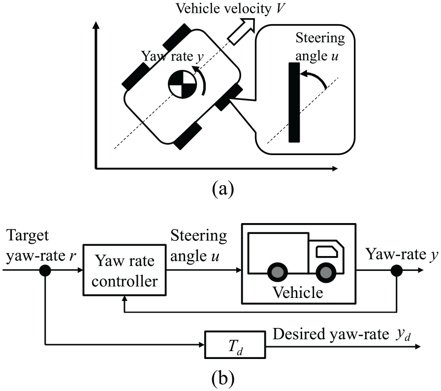
Control system configuration: (a) front-wheel-steering vehicle and (b) model-referenced (MR) control.
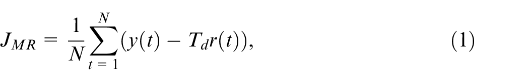
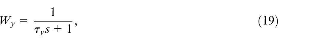
Furthermore, we briefly describe the characteristics of lateral vehicle dynamics because a model-free approach is adopted. The physical model of the general nonlinear two-track vehicle dynamics is described in Appendix 1. Lateral vehicle dynamics depend on vehicle velocity, as shown in Figure 2. This figure shows the frequency response of a vehicle model. 1 At higher vehicle velocities, the DC gain is higher and the cut-off frequency is lower, while at lower velocities, the DC gain is lower and the cut-off frequency is higher. Therefore, lateral vehicle dynamics have parameter-varying characteristics for a given vehicle velocity. Additionally, the weight of a truck changes according to the loads it carries, that is, the vehicle dynamics characteristics are variable. To address these problems, we adopt a model-free approach; in this approach, we do not use the model of the system to be controlled. We aim to construct the yaw rate MFC and introduce the data-driven design method for the proposed MFC from single-experiment data to realize model matching as follows:
where
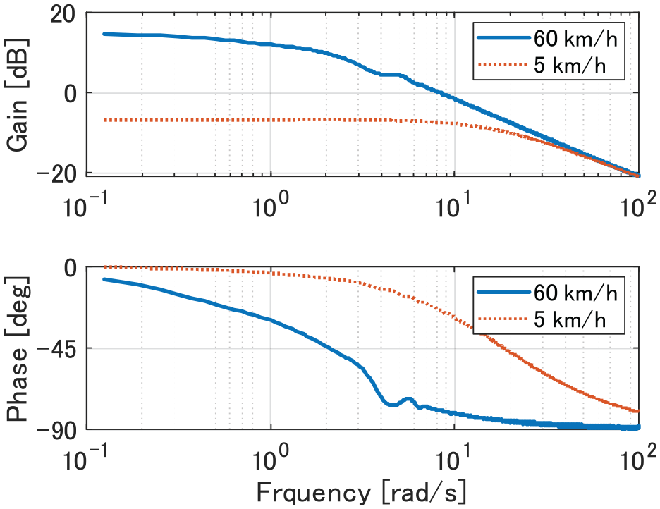
Frequency response characteristics of the vehicle dynamics.
Controller structure
In this section, we describe the traditional MFC based on an ultra-local model and introduce practical MR-MFC.
Traditional MFC based on the ultra-local model
The controlled object is a nonlinear single-input single-output system that can be expressed as follows:
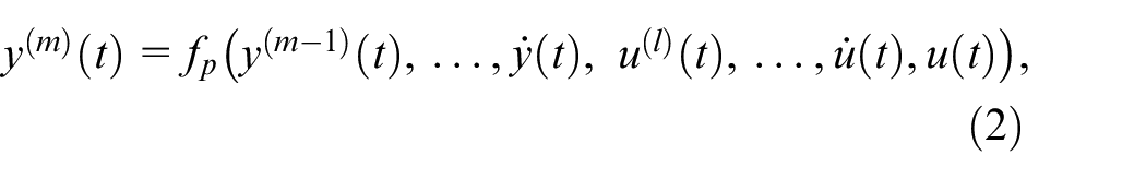
where

where

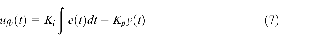
Figure 3 shows the traditional MFC based on an ultra-local model; in the figure, r represents the set point and P represents the system to be controlled. Based on the ultra-local model, the MFC law is given as

with

where
with

Model-free control (MFC) with an ultra-local model.
Practical MR-MFC
In this section, we introduce MR-MFC. Based on (4) and (5), the traditional MFC yields the following relationship:
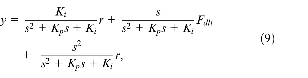
where

In (9), the first term represents feedback control; the second term represents the estimation error for
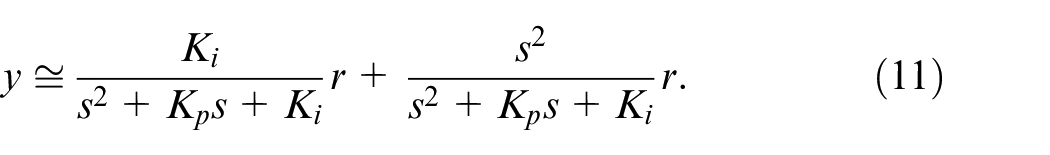
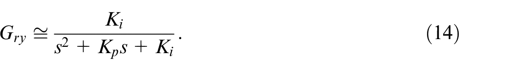
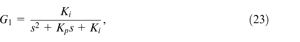
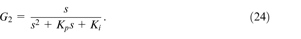
As shown in the problem formulation, we explore the model-matching problem as well as prior data-driven control studies. For model matching, the feedforward term is not necessary. For instance, when the reference model is given as
the PI gain can be uniquely and analytically determined as

where
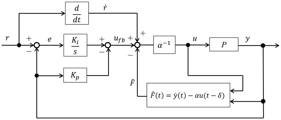
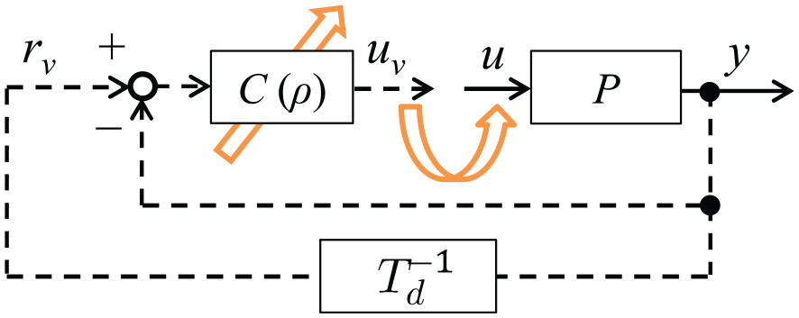
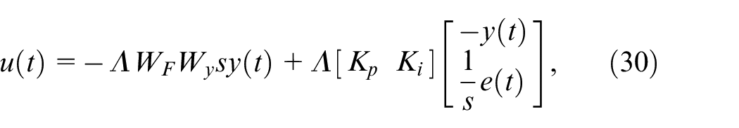
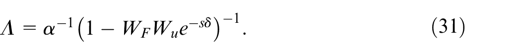
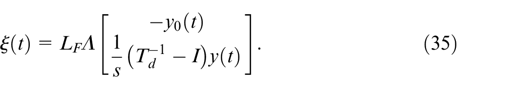
Thus, model-matching is realized without the feedforward term. In addition, the feedforward term derived from the ultra-local model may negatively affect model matching. Thus, MR-MFC comprises a feedback controller and an estimator as shown in Figure 4. The desired closed-loop response can be realized under the control law given as

In practice, noise reduction is necessary to estimate F for an actual system. Algebraic identification techniques for estimating F have been proposed earlier 15 :
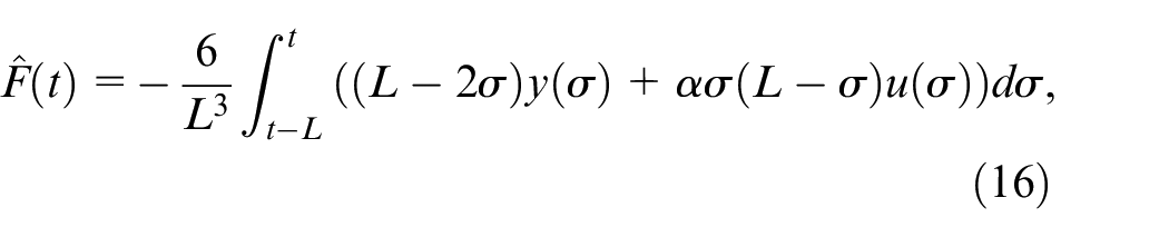
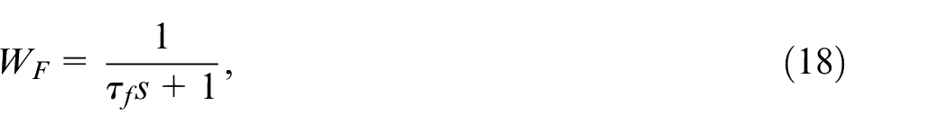
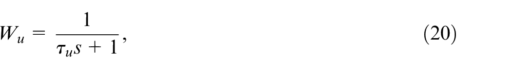
where L depends on the sampling period and noise level. This approach realizes accurate estimation. However, it may be difficult to implement the mass-product controller because the order of the estimator increases for short sampling periods. Hence, we use low-pass filters that are more suitable for implementation. The estimator is expressed as

where
where
In general, the PI gain determined using (13) cannot provide the desired tracking performance because the analytical solution (13) is based on the assumptions that
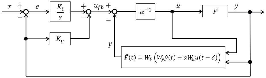
Model-referenced MFC (MR-MFC) with an ultra-local model.
The difference between this study and previous studies on MFC tuning is described here. In a previous study,
41
a data-driven design based on fictitious reference feedback tuning was proposed for extended MFC; however, a linear system was targeted and
Stability analysis
Let us now consider the stability analysis of MR-MFC. Practical MR-MFC includes the error estimation

with
Let us assume bounded error estimation, that is,
Data-driven design for MR-MFC
In this section, we first describe the standard VRFT, which involves data-driven tuning, and then describe the data-driven method for MR-MFC.
Standard VRFT
VRFT
28
is a direct controller parameter-tuning method for a linear time-invariant (LTI) feedback controller with a prespecified structure. Tuning is achieved using input/output data in an open-loop test without a system model. Furthermore, VRFT is an MR data-driven control that automatically tunes the control parameter

Using
with

where
with

Concept of virtual reference feedback tuning (VRFT).
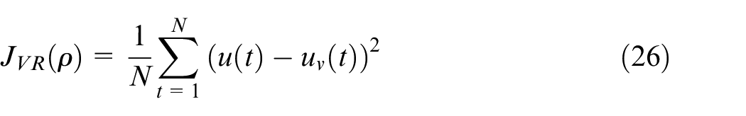
Data-driven tuning of the proposed controller
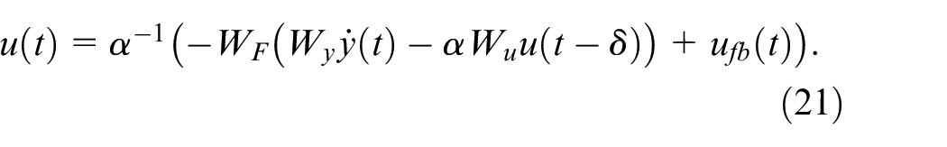
Herein, we introduce DD-MR-MFC based on VRFT. Based on practical MR-MFC, the control input is given as
with
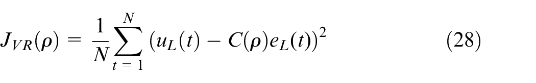
By replacing
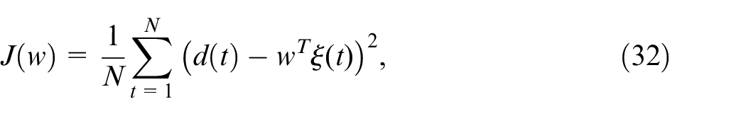
with


and
Because the cost function is convex, the optimized parameters can be obtained using the least-squares method:
with

and

Algorithm
The algorithm for the direct data-driven tuning method of MR-MFC is as follows:
[Step1] Obtain the input/output data via a test.
[Step3]After calculating
In implementing the controller, we use the controller (21) with the tuned parameters.
Simulation verification
We verified the effectiveness of the proposed method using a high-accuracy multibody vehicle simulator. We compared the performances of the proposed method, initial PI controller, popular data-driven approach using the PI controller tuned by VRFT, MR-MFC tuned by (13), and MR-MFC tuned by the proposed method. Additionally, the effectiveness of the controller performance for different vehicle weights was examined.
Simulation environment
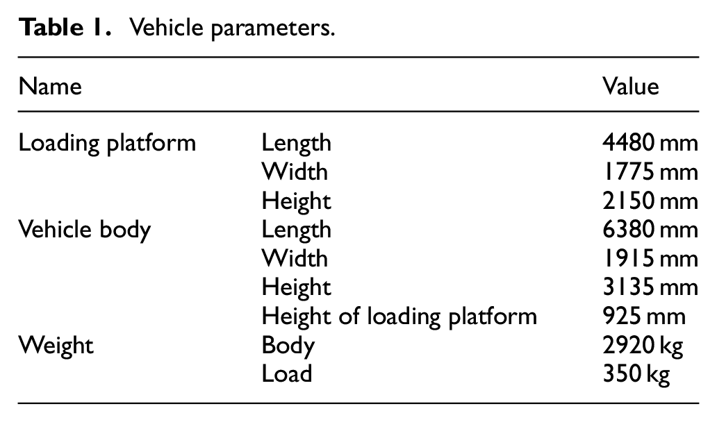
We used a high-accuracy vehicle simulator that combines MATLAB/Simulink and TruckMaker (IPG Inc.). 43 TruckMaker is exclusively used for testing commercial vehicles. As the vehicle models in TruckMaker are designed based on various experimental data and mechanism analyses, they can reproduce nonlinear vehicle characteristics with high accuracy. In the simulation, we built a vehicle model and a running course using TruckMaker and created a controller using MATLAB/Simulink. We set the sampling period of the controller to 0.01 s and discretized the controller. Figure 6 shows the multibody vehicle in TruckMaker. This vehicle model implemented in TruckMaker was modeled as a multidegree-of-freedom multibody dynamics system to reliably simulate the vehicle motion characteristics of the truck ISUZU ELF (Table 1). 44
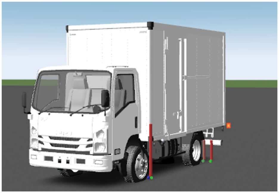
Vehicle model in TruckMaker.
Vehicle parameters.
Initial run results
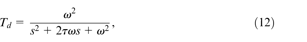
This section describes the initial results. The desired transfer function is defined as follows:
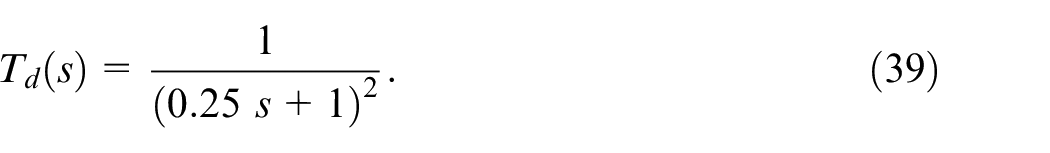
This reference model has poles with a negative real part, which helps avoid overshoot. The order of the reference model is determined using (12). The time constant is determined based on previous studies. 45 In practice, the reference model parameters can be set based on prior system information. The fixed PI controller
is used in a closed-loop test for measuring the initial data.
Time-series data for the initial proportional–integral (PI) controller.
Time-series data for the initial proportional–integral (PI) controller at different velocities.
Tuning results
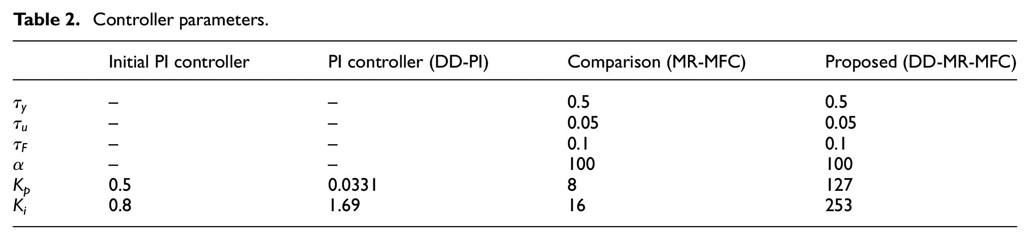
We examined the performances of the PI controller tuned via VRFT (DD-PI), MR-MFC with (13), and MR-MFC tuned using the proposed method (DD-MR-MFC). Table 2 summarizes the tuned parameters. Based on the results of the stability analysis (Section “Stability analysis”), we confirmed that for MR-MFC and DD-MR-MFC, the real part of the poles has negative values. We compared the yaw rate responses by varying the vehicle velocity in the range of 5–60 km/h.
Controller parameters.
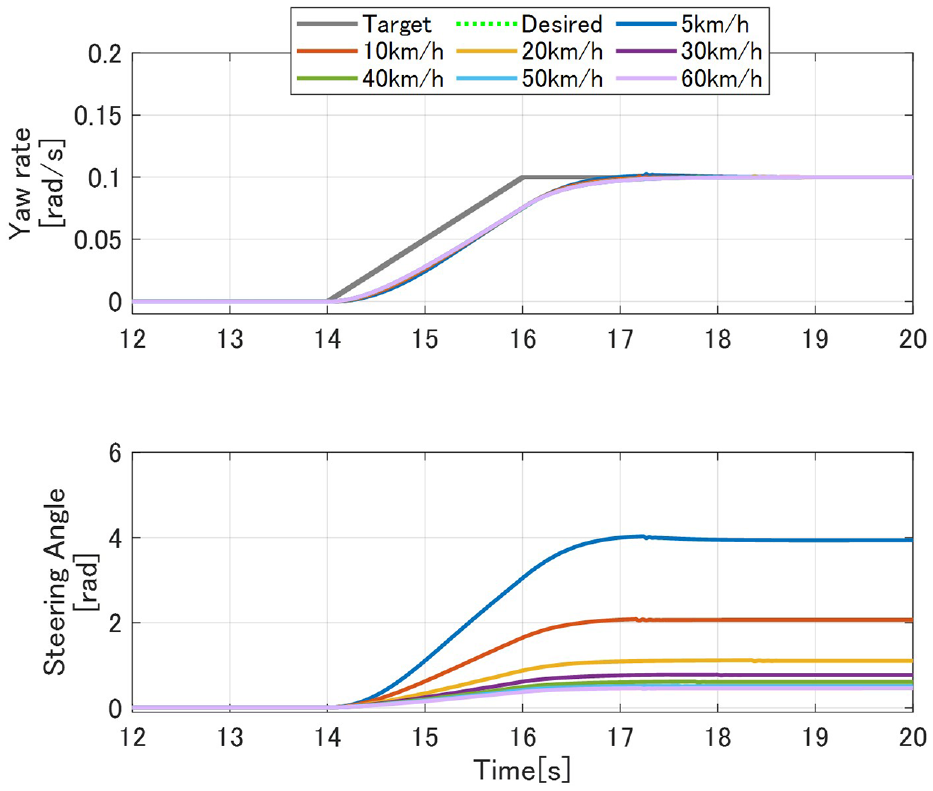
First, we confirmed the results of the tuned standard PI controller. Figure 9 shows the numerical simulation results for the fixed-gain PI control tuned via VRFT, which is a commonly used data-driven method; this figure shows the plotted yaw rate (output) and steering angle (input) values. The broken green line in the figure indicates the desired transfer function response. The actual yaw rate is close to the desired responses only at a vehicle velocity of 30 km/h. At other vehicle velocities, the desired and actual yaw rates are different. This implies that the standard PI controller, which is an LTI controller, cannot achieve high tracking performance for the lateral vehicle dynamics that depend on vehicle velocity (see section “Problem formulation”). Thus, the result indicates that a controller structure that is applicable to nonlinear (or LPV) systems is necessary for realizing the desired vehicle lateral dynamics control.
Time-series data with the fixed PI control tuned by VRFT (DD-PI).
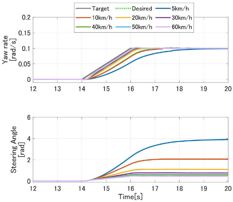
Next, we consider the MR-MFC tuned using equation (13). Figure 10 shows the time-series data for this control, where the yaw rate (output) and steering angle (input) values are plotted. This figure shows that the actual yaw rates do not follow the desired responses for different vehicle velocities. As can be seen, the tracking error at low velocities is larger than that at high velocities. This is because the dynamic characteristics undergo greater changes at low velocities than at high velocities. In the analytical tuning scheme (13), we assume that the low-pass filter lag is not considered for estimating F. However, in practice, a low-pass filter is essential for dealing with noise, and the MR-MFC is equipped with such a filter. Thus, the controller with the parameters tuned by (13) provides a low tracking performance. This implies that it is essential to obtain optimal parameters in addition to selecting an appropriate structure of MR-MFC, which has the potential for application to nonlinear (or LPV) systems.
Time-series data with MR-MFC parameters tuned by (13).
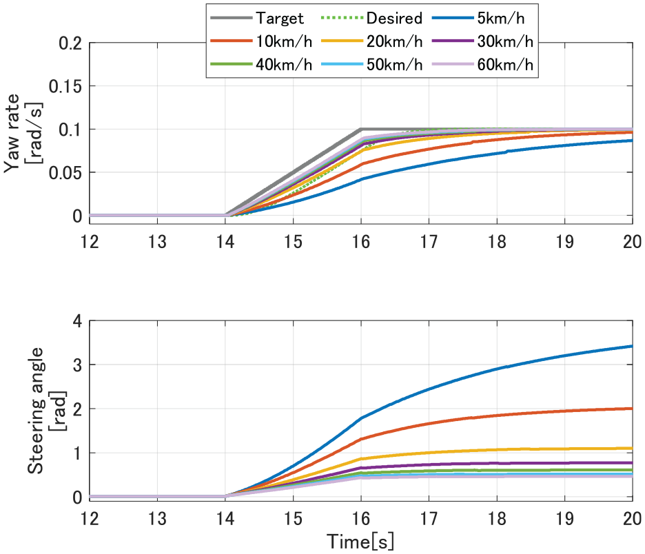
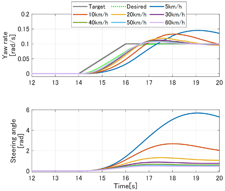
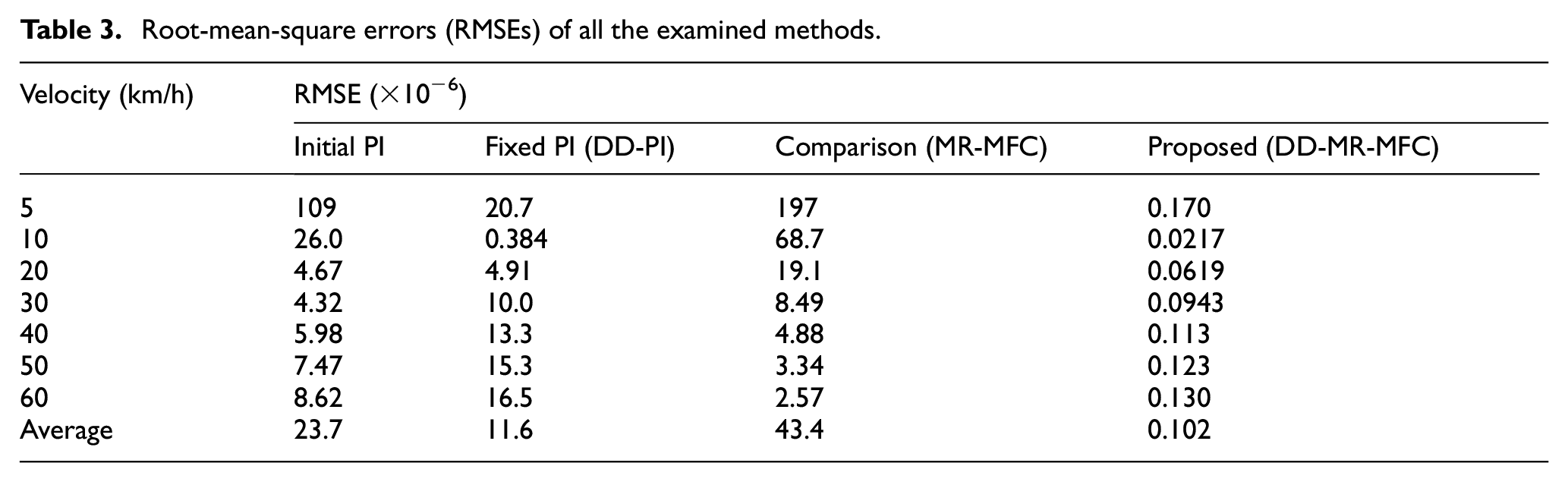
Finally, we tested the proposed method. Figure 11 shows the time-series data applied to the proposed method, that is, DD-MR-MFC, in which the MR-MFC is tuned using a data-driven method. The yaw rate (output) and steering angle (input) values are plotted in the figure. The desired and the actual yaw rate signals almost overlap. The proposed method provides a high tracking performance for vehicle velocities of 5–60 km/h. Table 3 lists the root-mean-square errors (RMSEs) of all methods. The data in the table show that the proposed method provides the best performance. The RMSE for DD-MR-MFC was approximately 1/100th of that for DD-PI and approximately 1/400th of that for the MR-MFC tuned using (13). Thus, the effectiveness of the MR-MFC structure and data-driven tuning method was established. Furthermore, the performance of MR-MFC tuned by (13) was lower than that of DD-PI control in the velocity range of 5–20 km/h. This is because the estimation delay increases in low-velocity ranges where a large change in the steering angle is required. In DD-MR-MFC, the controller parameters are optimized to compensate for the estimation error. A detailed discussion is provided in the next section.
Time-series data with the proposed method (DD-MR-MFC). The yaw rate of the desired and proposed methods almost overlap.
Root-mean-square errors (RMSEs) of all the examined methods.
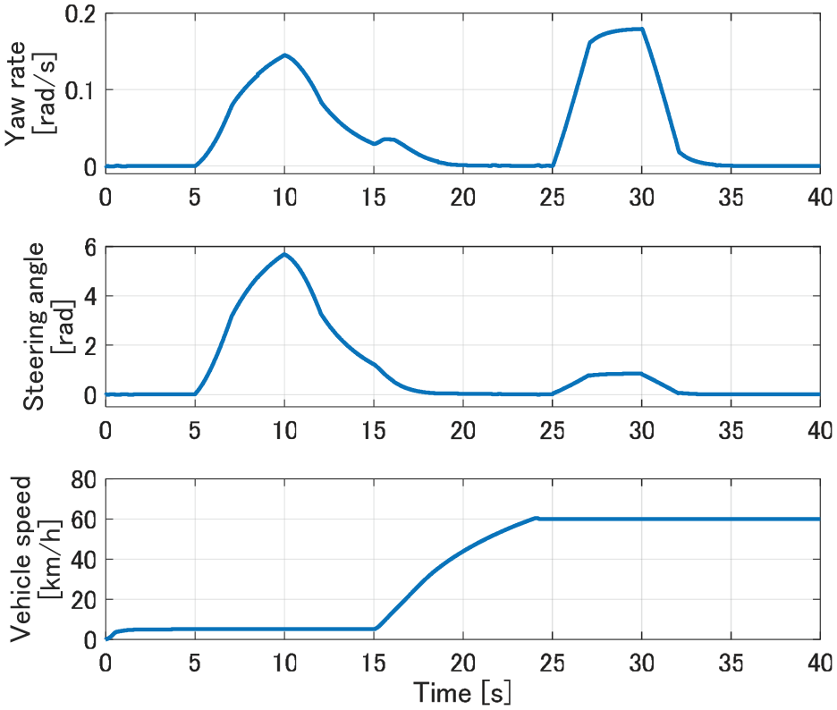
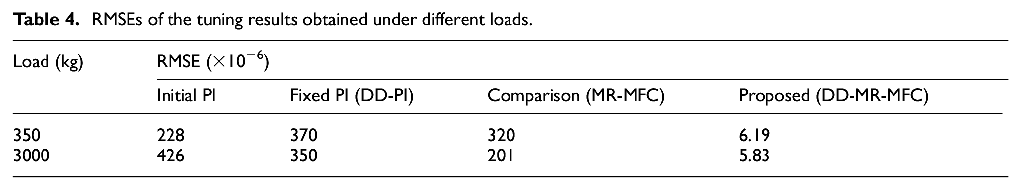
We confirm the effectiveness of the proposed method under varying vehicle velocity and various setpoints. Figure 12 shows the time-series data for changing the vehicle velocity using the proposed method; the yaw rate (output), steering angle (input), and vehicle velocity are plotted. The actual yaw rate follows the desired signal. In addition, we confirmed that the proposed method provides robust performance under different vehicle loads. This consideration is particularly important for trucks, which are vehicles that tend to carry widely varying loads. Notably, we used the controller designed for a load of 350 kg (Table 2). Table 4 lists the RMSEs for the same target signal and velocity as those presented in Figure 12 and for a load of 3000 kg in addition to 350 kg. The data presented in Table 4 show that the proposed method provides the best tracking performance for different loads. These results show that the proposed DD-MR-MFC is effective for the lateral dynamics control of trucks despite the simple controller. Such performance cannot be easily achieved using the model-based approach because it requires an accurate vehicle model, including real-time weight estimation. Additionally, the model-based controller tends to be complex. Thus, the effectiveness of the proposed method was validated.
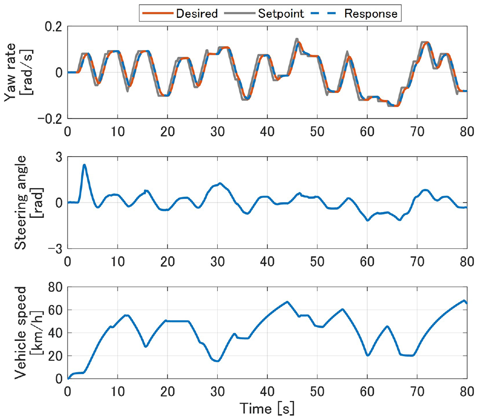
Time-series data for the case of changing vehicle velocity with DD-MR-MFC. The yaw rate of the desired and response lines almost overlap.
RMSEs of the tuning results obtained under different loads.
Discussion
We applied the proposed DD-MR-MFC method to vehicle lateral dynamics control. The effectiveness of the proposed method was verified by comparing its performance with the performances of other methods, namely, DD-PI and the MR-MFC tuned using the analytical tuning scheme. The compared methods did not provide good tracking performance with respect to yaw rate. Because DD-PI used the LTI controller, it could not be applied to nonlinear lateral dynamics although PI gain is optimized. In case of MR-MFC, the analytical scheme (13), which requires the assumption of ideal estimation, did not provide the optimal parameters because of the estimation errors of the low-pass filters. Conversely, the proposed method realized high tracking performance for variable vehicle velocities and weights. The proposed method provided the controller parameters that compensate for the effect of the estimation error. The simulation results showed that MR-MFC optimized using a data-driven method is effective for vehicle lateral dynamics control. The proposed data-driven tuning method does not need the model to be controlled and provides the optimal control parameters from single-experiment time-series data. Moreover, this method incurs considerably low optimization cost because it uses the least-squares method. Additionally, the proposed practical MR-MFC has a very simple structure, and it is easy to implement the mass-produced controller.
Furthermore, we discuss the parameters listed in Table 2. The difference between the PI gains of DD-PI and MR-MFC obtained using (13) is explained. When the analytical solution (13) is used, we assume that the error of estimation F is zero (
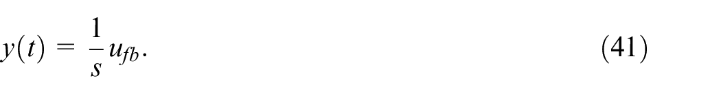
That is, the feedback component of MR-MFC treats (41) as the target plant. Notably, so long as the assumption of
Conclusion
In this study, we propose data-driven MR-MFC, termed DD-MR-MFC, based on an ultra-local model for vehicle yaw rate control. DD-MR-MFC combines the controller structure of the MR-MFC and the VRFT-based data-driven design methods. The effectiveness of the proposed method was verified using a vehicle simulator. Moreover, its performance was compared with those of other methods, such as the standard PI control tuned via VRFT and the MR-MFC tuned using an analytical tuning scheme based on the closed-loop characteristics of MR-MFC. The current methods did not achieve the desired yaw rate control; conversely, the proposed method realized the desired yaw rate response using single-experiment data without modeling the system to be controlled. In future research, we aim to verify the validity of the proposed method using an actual automated vehicle.
Footnotes
Appendix 1
The general two-track vehicle model with front wheel steering is described, as shown in Figure A1.46–48 According to Newton’s second law, the vehicle dynamics can be expressed as
with
where
where
with
Declaration of conflicting interests
The author(s) declared no potential conflicts of interest with respect to the research, authorship, and/or publication of this article.
Funding
The author(s) received no financial support for the research, authorship, and/or publication of this article.