
Abstract
Based on the existing theory of EHB braking system, a new dual-source redundant braking system (DSRB) is proposed in this paper. The proposed DSRB is improved on the classic ESP system structure with two sets of motor hydraulic pumps, four throttle valves and two balance valves used to replace the failed oil inlet and outlet valves added in it. Then, the requirements of redundancy, reliability of intelligent vehicle braking system can be met by the system. The wheel cylinder pressure of DSRB system is accurately regulated by PID control algorithm. Finally, the co-simulation based on AMEsim/Simulink were implemented to verify the accuracy and reliability of the braking efficiency of the DSRB. Results show that the designed DSRB has fault tolerance even in the case of partial failure, that is, inlet and outlet valve failure and complete failure, that is, inlet and outlet valve and hydraulic motor failure at the same time. And good braking efficiency, boosting speed and pressure regulation accuracy are still available.
Keywords
Introduction
With the development of electric vehicles (EVs), hybrid electric vehicles (HEVs) and intelligent vehicles, the Brake-By-Wire (BBW) system are now playing a more important role than before.1–5 The progress of automatic driving and driverless vehicle technology also puts forward more stringent requirements for redundant functions of vehicle braking system. The future braking system is required to be integrated, control-by-wire and high reliable. At this stage, the traffic accidents caused by brake system failure are still frequent. Among the traffic accidents caused by vehicle faults, 45% are caused by braking system faults. The reliability and redundancy of braking system are becoming more and more vital for the improvement and research of braking system. Especially under the condition of partial or complete failure of braking system hardware, its redundancy performance is crucial for the safety of L3 and above intelligent driving vehicles. This requires that the braking system should be both redundant and efficient with certain braking maintained even when some components fail. Moreover, faster pressurization speed and more accurate pressure regulation accuracy will be helpful to meet the requirements of vehicle longitudinal braking control and lateral stability control.
Since the existing electronic hydraulic braking system (EHB) only changes the traditional vehicle braking system on the wire harness control, the low cost allows it to become the mainly used system of the wire controlled braking system.6–10 However, with accumulator is used as the only pressure source, the basic braking of the vehicle in EHB can only be realized through the driver’s operation when active pressure control circuit fails partially. Also, the requirements of intelligent or driverless vehicles for fault tolerance of braking system seems difficult to be met in EHB. Therefore, some enterprises and scholars have done a lot of researches on the improvement of EHB system structure.11–13 Also the pressure following algorithm of system has also been studied a lot.14–17 BOSCH has introduced the latest generation of ibooster + ESP-hev braking system.18,19 It became a template for the subsequent EHBs. 20 In which ibooster and hydraulic pump are used and the redundancy of the system is considered. However, the braking efficiency and the reliability will be greatly affected for ibooster failure. Only two linear valves are retained in the third generation Puris electro-hydraulic brake system ECB of Toyota leading to the lower cost. Moreover, the hydraulic source is independent from the design of ECB, which can realize auxiliary braking to some extent and improve the failure braking capacity of the system. Tan et al. improved the existing I-EHB system structure, adopted a three chambers master cylinder, and omitted the pedal simulator. This allowed for the good application of three different modes: ABS, conventional braking and failure protection. Wang et al. proposed a distributed EHB system. 21 Pan et al. proposed a more compact P-EHB system, which reduced the number of electromagnetic valve bodies and simplified the system oil circuit. And the cyclic scheduling method is adopted for pressure control in P-EHB. The simulation results show that the pressure response effect of the system is superior. 22 In addition, the existing research results can still be further improved. It mainly includes: although the redundant design is considered for the EHB braking system combined with the action of booster mechanism, the braking efficiency during redundant braking is difficult to ensure. And the optimization of coordinated control is very complex. Moreover, the electro-hydraulic braking system with multiple power sources has complex structure, many components and high cost, which is difficult to realize commercialization.
Therefore, a new dual-source redundant braking system (DSRB) is proposed in this paper to meet the requirements of redundancy, reliability and fault tolerance. First, the structure and working principle of the system under failure mode are introduced. Then the mathematical model of DSRB system and key components is established. Furthermore, a PID algorithm is applied to the braking system to facilitate the wheel cylinder pressure control. Finally, the co-simulation based on AMEsim/Simulink are implemented to verify the wheel cylinder pressure of the DSRB follows the response.
Design and analysis of DSRB
EHB configurations
The existing electronic hydraulic braking system (EHB) changes the traditional vehicle braking system on the wire harness control. Also, the vacuum booster unit and related hydraulic components are omitted in the structure. And the brake master cylinder is no longer directly connected with the brake wheel cylinder anymore. 22 After the braking intention of the driver is obtained through the electronic pedal, the control signal is analyzed and calculated by the electronic control unit (ECU), which is then sent to the control unit to establish the braking pressure. The architecture of EHB is illustrated in Figure 1.
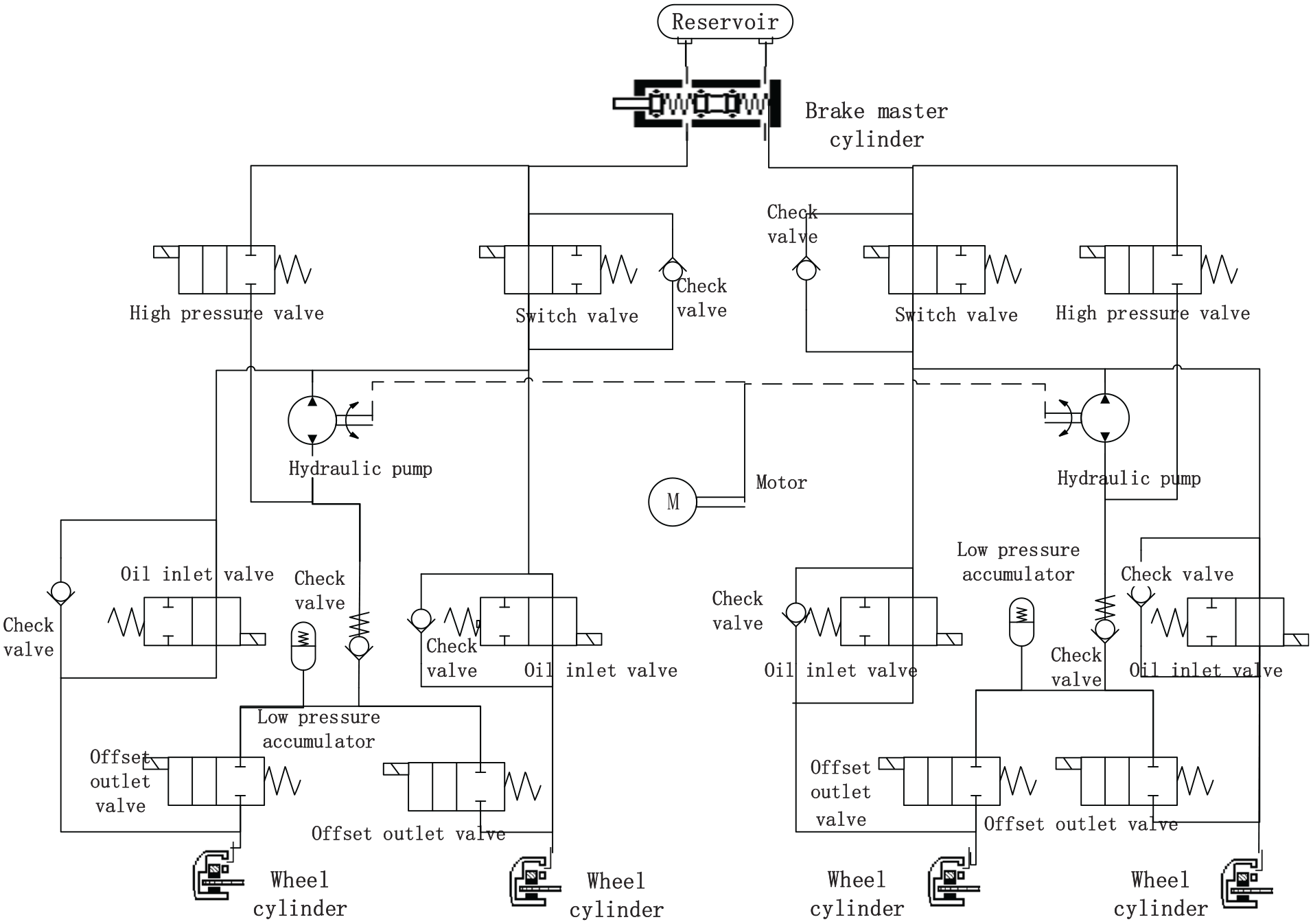
Structure of EHB system.
The actuator of the automotive EHB system has two working modes: passive voltage regulation and active voltage regulation when the auxiliary effect of the booster mechanism is not considered.
The passive voltage regulation mode is composed of three working conditions: ABS pressurization, ABS pressure maintaining and ABS pressure reducing. The switch valve is always open and the high-pressure valve is always closed. During the ABS pressurization which is also called conventional braking stage, the oil inlet valve is opened while the offset outlet valve is closed, and the motor and hydraulic pump are not involved in the work. The brake fluid in the brake master cylinder is finally pressed into the brake wheel cylinder through the switch valve and oil inlet valve. Therefore, the braking pressure is generated to make the vehicle realize braking. During the ABS pressure maintaining stage, the oil inlet valve is energized and closed, while the brake fluid in the pipeline stops flowing. During the ABS pressure reducing stage, the oil inlet valve is energized and closed, while the offset outlet valve receives PWM signal and opens with a certain opening. The brake fluid flows from the wheel cylinder into accumulator. Meanwhile, the brake fluid stored in the accumulator is pumped back to the reservoir and brake master cylinder by the hydraulic pump driven by the motor.
The active voltage regulation mode is composed of three working conditions: ESC pressurization, ESC pressure maintaining and ESC pressure reducing. The motor hydraulic pump is always in operation. During the ESC pressurization stage, the high-pressure valve is energized and opened while the switch valve is energized and closed, and the oil inlet valve receives PWM signal and opens with a certain opening. Also, the offset outlet valve is closed, and the brake fluid is pumped into the wheel cylinder from the reservoir and the brake master cylinder by the hydraulic pump driven by the motor. During the ESC pressure maintaining stage, the high-pressure valve, switch valve, oil inlet valve and offset outlet valve are closed. And the brake fluid stored in the accumulator is pumped back to the reservoir and the brake master cylinder by the hydraulic pump driven by the motor. During the ESC pressure reducing stage, the status of each solenoid valve is the same as that during conventional braking. The brake fluid in the wheel cylinder flows back from the wheel cylinder to the master cylinder due to the differential pressure, and the pressure decreases. At this time, part of the brake fluid is pumped back to the main circuit by the hydraulic pump driven by the motor, and the pressure of the main circuit is established in advance.
However, the EHB braking system fails when the control circuit of it fails partially or completely. Also, it will then switch to the traditional hydraulic system for braking operation. The braking efficiency of EHB will be difficult to be guaranteed under partial failure conditions when the auxiliary effect of the booster mechanism is not considered. In other words, EHB does not have certain fault tolerance and reliability.
Proposal of DSRB system
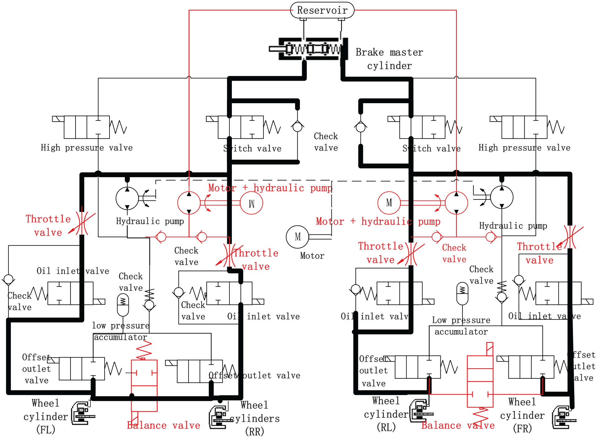
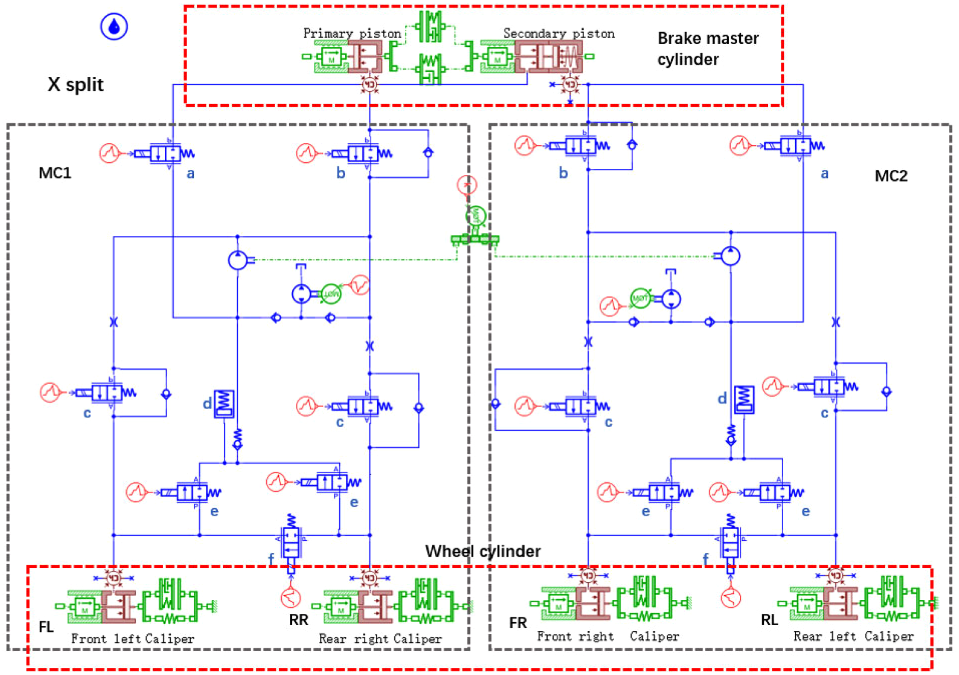
Based on the above analysis, the concept of dual-source redundant braking system (DSRB) is proposed in this paper. The scheme is illustrated in Figure 2. The proposed DSRB is improved on the classic ESP structure with two sets of motor hydraulic pumps, four throttle valves and two balance valves added in it. The pipeline is still arranged in X-shape. In order to achieve faster and stable pressure regulation control the motor hydraulic pump and throttle valve are added. Also, it makes the braking system still have good braking efficiency and maintain a certain braking deceleration under the condition of booster mechanism failure or original motor hydraulic pump failure. In addition, when the oil inlet valve or offset outlet valve of the system fails, the added balance valve can be used as a functional substitute. And the wheel cylinder pressure corresponding to the failed solenoid valve can also be adjusted accordingly.
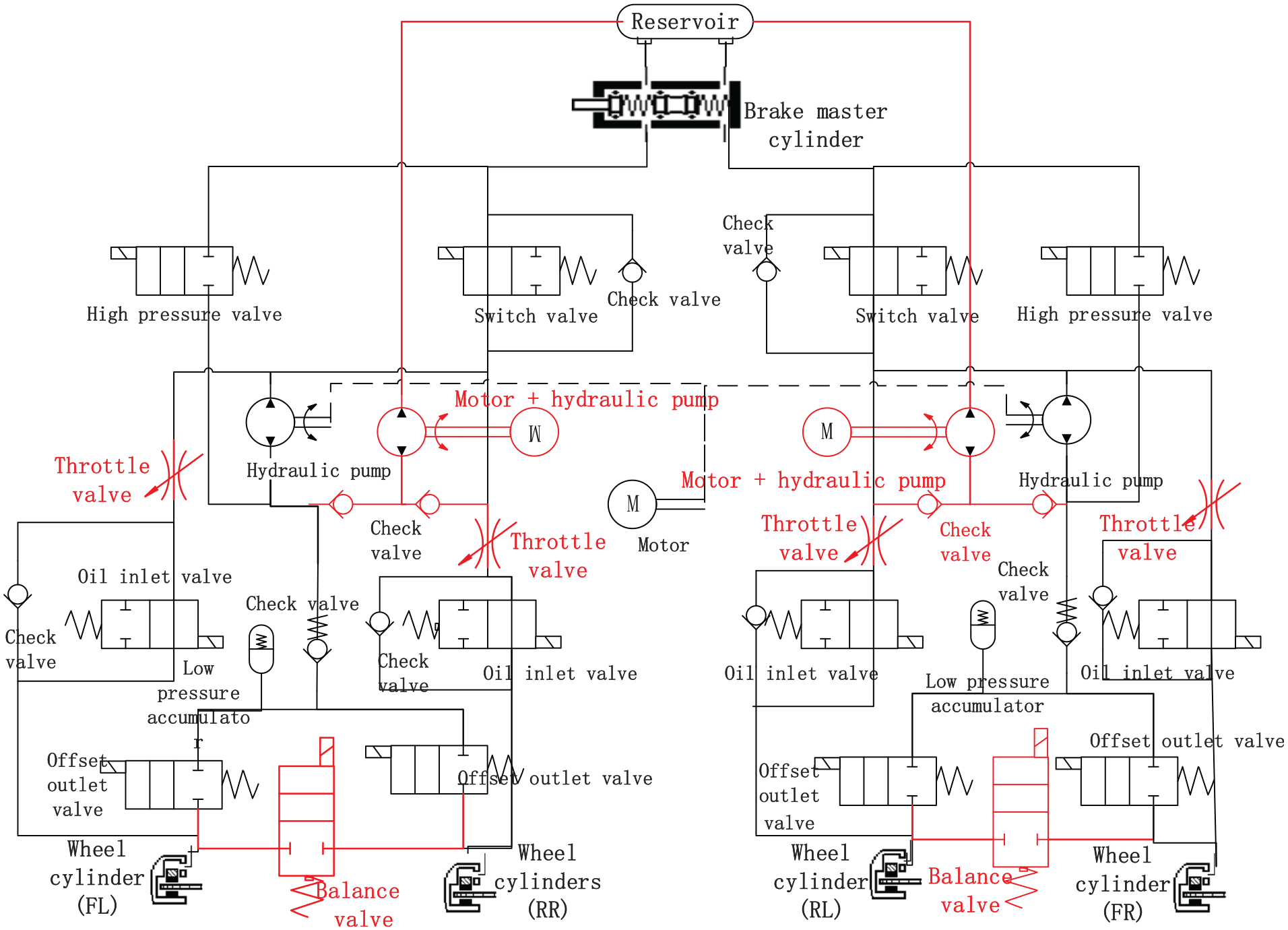
Structure of DSRB system.
Different from the existing EHB, good braking efficiency and braking deceleration can be realized in DSRB under all working conditions: normal working condition, partial failure condition and complete failure condition. Also, the additional effect of the booster mechanism is not taken into account. The architecture of DSRB is illustrated in Figure 2.
Failure condition analysis of DSRB
The active and passive voltage regulation of the existing EHB under normal working conditions can also be realized by the designed DSRB. Simultaneously, the normal braking can still be completed by DSRB with the booster mechanism fails, the original motor hydraulic pump fails and the solenoid valve fails. At the same time, certain braking deceleration and braking efficiency can be guaranteed.
The following description is given for the working mode of braking under the failure condition of DSRB system. The DSRB failures mainly include: failure of booster mechanism, failure of original motor hydraulic pump and failure of oil inlet valve or offset outlet valve.
The additional motor hydraulic pump operates during braking when DSRB detects that the booster mechanism fails. And the functions of pressurization, pressure maintaining and pressure reducing of brake wheel cylinder can be realized. At this time, the working state of all components of DSRB and the direction of brake fluid flow are consistent with those when the system is not failed. And the system pressure building and pressure regulation speed increase are realized by additional motor hydraulic pump.
When DSRB detects that the original motor hydraulic pump fails, the working state of all components of DSRB and the direction of brake fluid flow are consistent with those when the system is not failed in passive voltage regulation. However, when DSRB is in active voltage regulation, the additional motor hydraulic pump operates. The ESC pressurization condition is illustrated in Figure 3. The motor rotates forward when pressurizing and the hydraulic pump is driven to pump the brake fluid in the reservoir into the brake wheel cylinder. Then, the brake pressure is generated. When DSRB is in ESC pressure maintaining, the motor reverses and the hydraulic pump is driven by the motor. And the brake fluid in the accumulator is pumped into the reservoir which is prepared for the next pressure reducing. In addition, the motor is still reversed when pressure reducing. The ESC pressure reducing condition is illustrated in Figure 4. The hydraulic pump is driven by the motor. And all the brake fluid in the accumulator is pumped into the reservoir.
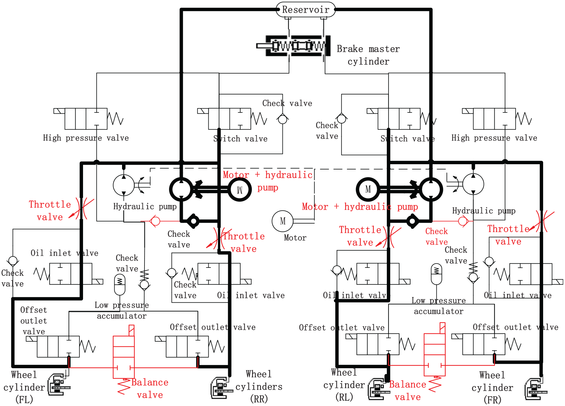
DSRB pressurization when motor hydraulic pump fails.
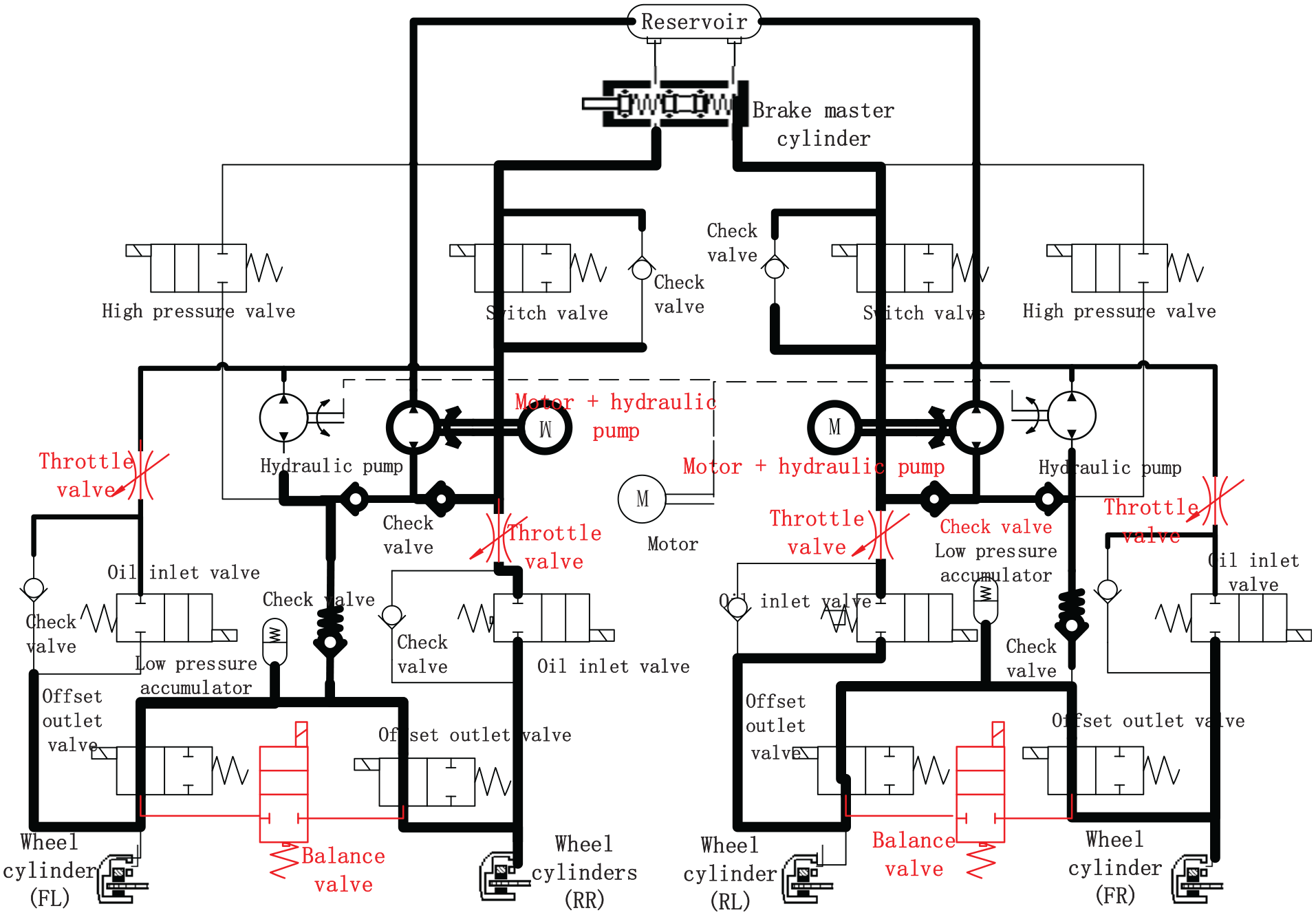
DSRB pressure reducing when motor hydraulic pump fails.
When DSRB detects that the oil inlet valve fails, the balance valve of the corresponding circuit is opened when DSRB is in pressurization. Also, the balance valve is closed when maintaining and pressure reducing. At this time, the function of the balance valve is equivalent to the original function of the failed oil inlet valve. And it is mainly used to pressurize the corresponding circuit of the system. Besides, when DSRB detects that the offset outlet valve fails, the balance valve of the corresponding circuit is opened when DSRB is in pressure reducing. Also, the balance valve is closed when pressure maintaining and pressurization. At this time, the function of the balance valve is equivalent to the original function of the failed offset outlet valve. And it is mainly used to depressurize the corresponding circuit of the system. Whether the oil inlet valve fails or the offset outlet valve fails, the working state of other none failed components is consistent with that of the system. And the direction of brake fluid flow is consistent with that when the system does not fail. Then taking the failure working state of the right rear wheel oil inlet valve as an example. The flow direction of the brake fluid in the pipeline is illustrated in Figure 5.
Working state of DSRB when right rear wheel oil inlet valve fails.
Hydraulic system model
Throttle model
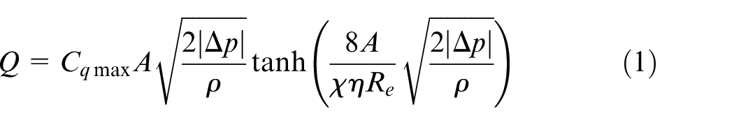
The throttle models are included in the structure of oil inlet valve, offset outlet valve, high pressure valve, switch valve and throttle valve of DSRB system. And each solenoid valve which plays an important role is mainly used to control the pressurization and decompression rate of the system. The throttle model established in this paper is shown in equation (1). 23 We cite the hydraulic system model of appendix 2 in this part of the manuscript.
where
Hydraulic pump model
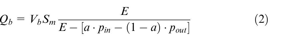
The hydraulic pump is installed in cooperation with the DC motor to generate braking pressure in DSRB. And the motor hydraulic pump operates in ESC mode of the braking system so that the better pressurization, pressure maintaining and decompression efficiency can be well realized. The ideal motor hydraulic pump is selected in this paper. According to the characteristics of the pump, the established mathematical model is shown in formula (2). 1
where
Low pressure accumulator model
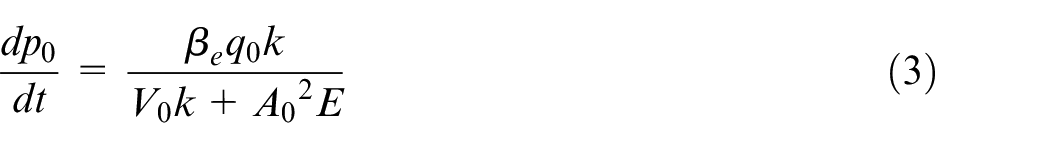
When the DSRB is depressurized, the low-pressure accumulator is mainly used to temporarily store the brake fluid discharged from the wheel cylinder so as to guarantee the rapid drop of wheel cylinder pressure. Generally, the accumulator is mainly composed of a mechanism similar to spring and piston. The spring is squeezed by the brake fluid, which increases the volume of stored brake fluid. Simultaneously, the brake fluid stored in the accumulator is pumped away by the hydraulic pump driven by the motor, which is pumped back to the brake pipeline, reservoir and brake master cylinder. The mathematical model of it is illustrated in equation (3). 23
where
DSRB system model
According to the structure of the designed DSRB system, the DSRB actuator model is established in AMESim software, as shown in Figure 6. The dual cavity brake master cylinder is adopted in DSRB system in this paper with double circuits arranged in a cross way. Because the sub model selection and parameter setting of the two circuits are the same, the whole braking system model is simplified in the actual simulation. In addition, since the parameters of front wheel and rear wheel in each circuit are slightly different, while the pipeline pressures of front wheel and rear wheel affect each other. Therefore, the pressure variation characteristics of the whole braking system cannot be accurately expressed by the single-wheel model. In this paper, a braking circuit, namely two-wheel model, is selected for wheel cylinder pressure control simulation experiment which includes the left front wheel and right rear wheel in it.
Hydraulic model of DSRB in AMEsim: (a) high pressure valve, (b) switch valve, (c) oil inlet valve, (d) low pressure accumulator, (e) offset outlet valve, and (f) balance valve.
Simulation of DSRB system
Pressure control method
This section accurately regulates the wheel cylinder pressure of DSRB system based on PID algorithm. Also, the control module is added on the basis of the simplified model of the braking system. Meanwhile, the expected brake pressure calculated by the upper control strategy and the actual brake wheel cylinder pressure are used as inputs. The opening signals of the oil inlet valve and offset outlet valve are outputs. Then, the precise control of wheel cylinder pressure is realized by controlling the opening and closing time and opening degree of the oil inlet valve and offset outlet valve.
The two-wheel model of DSRB built in AMESim is illustrated in Figure 7. And the Simulink interface module is connected in the model. The wheel cylinder pressures of the left front wheel and right rear wheel are used as inputs. While each solenoid valve signal and motor signal of the system are identified as outputs.
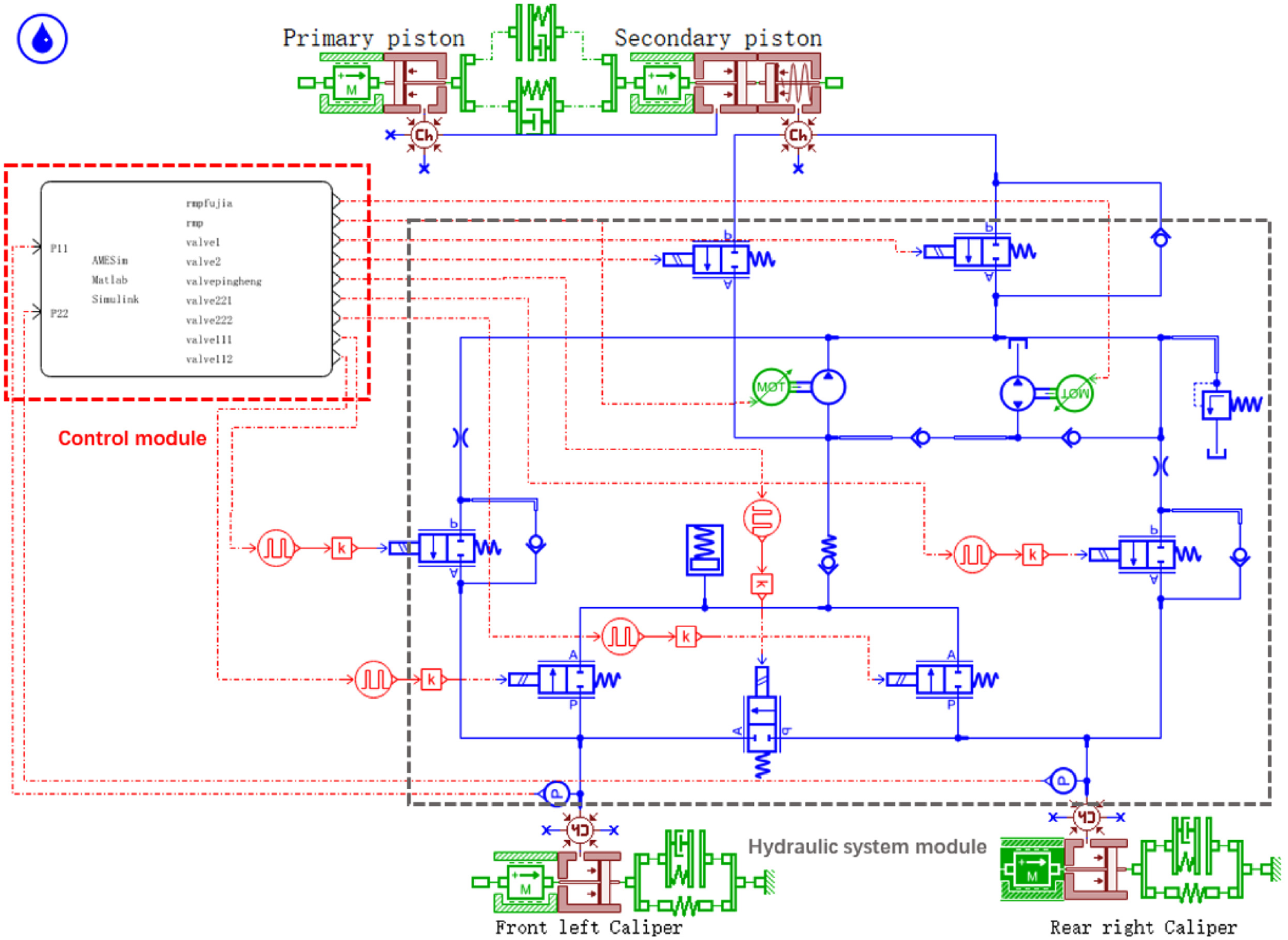
Two-wheel model of DSRB.
The control model of braking system built in Simulink is illustrated in Figure 8. And the AMESim interface module is connected in the model. Each solenoid valve signal and motor signal of the braking system are used as inputs. While the wheel cylinder pressures of the left front wheel and right rear wheel are identified as outputs. Then, the co-simulation based on AMEsim/Simulink are implemented to verify the wheel cylinder pressure of the DSRB follows the response.
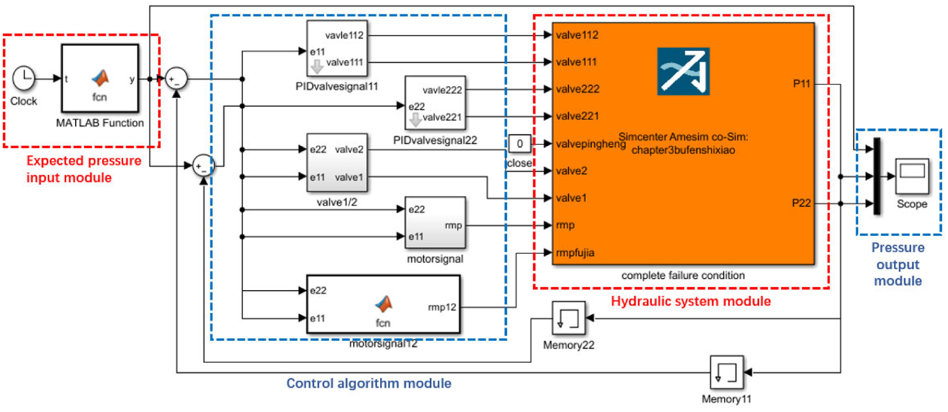
Control model of DSRB.
System parameter setting
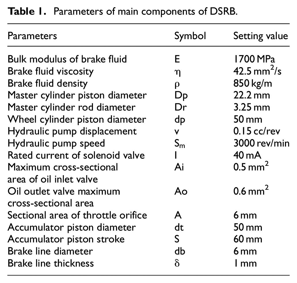
According to the mathematical model of hydraulic components and the characteristics of actual hydraulic braking system, the parameters of main components of DSRB are set. This facilitates the modeling and simulation analysis of the system in AMESim software. The parameters of the main components are shown in Table 1. 24
Parameters of main components of DSRB.
Simulation of pressure following control
Normal working condition
Set the desired pressure of DSRB wheel cylinder, as shown by the blue dotted line in Figure 9. Then the normal working condition of DSRB are simulated with a simulation time set as 10 s. Under normal working condition of the system, the p value of the PID controller controlling the pressure of the left front wheel cylinder is 0.011 mA/bar, and the p value of the PID controller controlling the pressure of the right rear wheel cylinder is 0.0026 mA/bar.
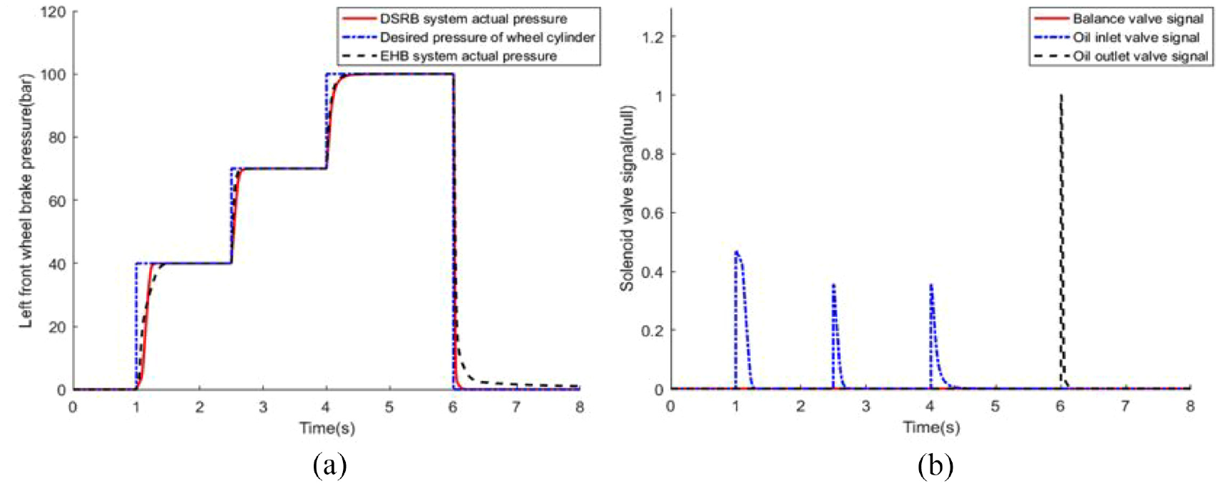
Normal working condition: (a) left front wheel brake pressure of DSRB and EHB and (b) PWM signal of left front wheel solenoid valve of DSRB.
Since the EHB braking system can also control wheel cylinder pressure under normal working condition, the wheel cylinder pressure tracking effect of DSRB and EHB under normal working condition is compared. Based on the brake pressure of the left front wheel cylinder, the simulation results are shown in Figure 9(a). Also, the PWM signal variation curve of DSRB left front wheel solenoid valve is presented in Figure 9(b).
As shown, the pressure control effect of DSRB and EHB wheel cylinder is almost the same under normal working condition. While the DSRB only has a faster speed of increasing and decreasing pressure. The pressurization of DSRB is 0.23 s faster than EHB system at 1 s, which then remains stable quickly. Meanwhile, the DSRB depressurizes rapidly at 6 s, and accurately depressurizes to 0 in a short time. The pressure drop is 0.4s faster than that of EHB. The design of dual motors makes the DSRB system designed have faster pressurization and decompression capabilities, and can realize pressure control more quickly.
Partial failure condition
Taking the failure of the oil inlet valve corresponding to the left front wheel as an example, partial failure condition of DSRB is simulated. Under partial failure condition of DSRB, the P value of the PID controller controlling the pressure of the left front wheel cylinder is 0.08 mA/bar, and the P value of the PID controller controlling the pressure of the right rear wheel cylinder is 0.0098 mA/bar. The brake pressure tracking curve of wheel cylinder of left front wheel and right rear wheel of DSRB is presented in Figure 10(a). And the PWM signal variation curve of DSRB left front wheel solenoid valve is presented in Figure 10(b).
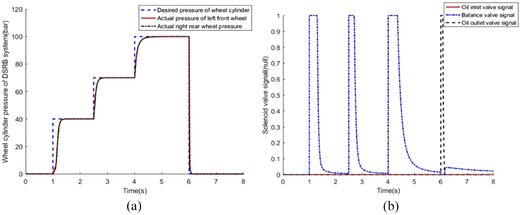
Partial failure condition: (a) brake pressure of wheel cylinder of DSRB and (b) PWM signal of left front wheel solenoid valve of DSRB.
As shown, the pressurization speed of DSRB is still fast at 1, 2.5, and 4 s under partial failure condition, which remains stable within about 0.3 s. Meanwhile, the DSRB depressurizes rapidly at 6 s, and accurately depressurizes to 0. Under partial failure condition, good braking efficiency and certain braking deceleration are still possessed by the DSRB. The design of the balance valve can replace the function when the oil inlet and outlet valves of the DSRB system fail, so as to normally realize the demand of system pressurization and pressure reduction.
Complete failure condition
Taking the failure of the oil inlet valve corresponding to the left front wheel and the failure of the motor hydraulic pump of the circuit as an example, complete failure condition of DSRB is simulated. Under complete failure condition of DSRB, the p value of the PID controller controlling the pressure of the left front wheel cylinder is 0.011 mA/bar, and the p value of the PID controller controlling the pressure of the right rear wheel cylinder is 0.0026 mA/bar. The brake pressure tracking curve of wheel cylinder of left front wheel and right rear wheel of DSRB is presented in Figure 11(a). And the motor pump and additional motor pump signals are illustrated in Figure 11(b).
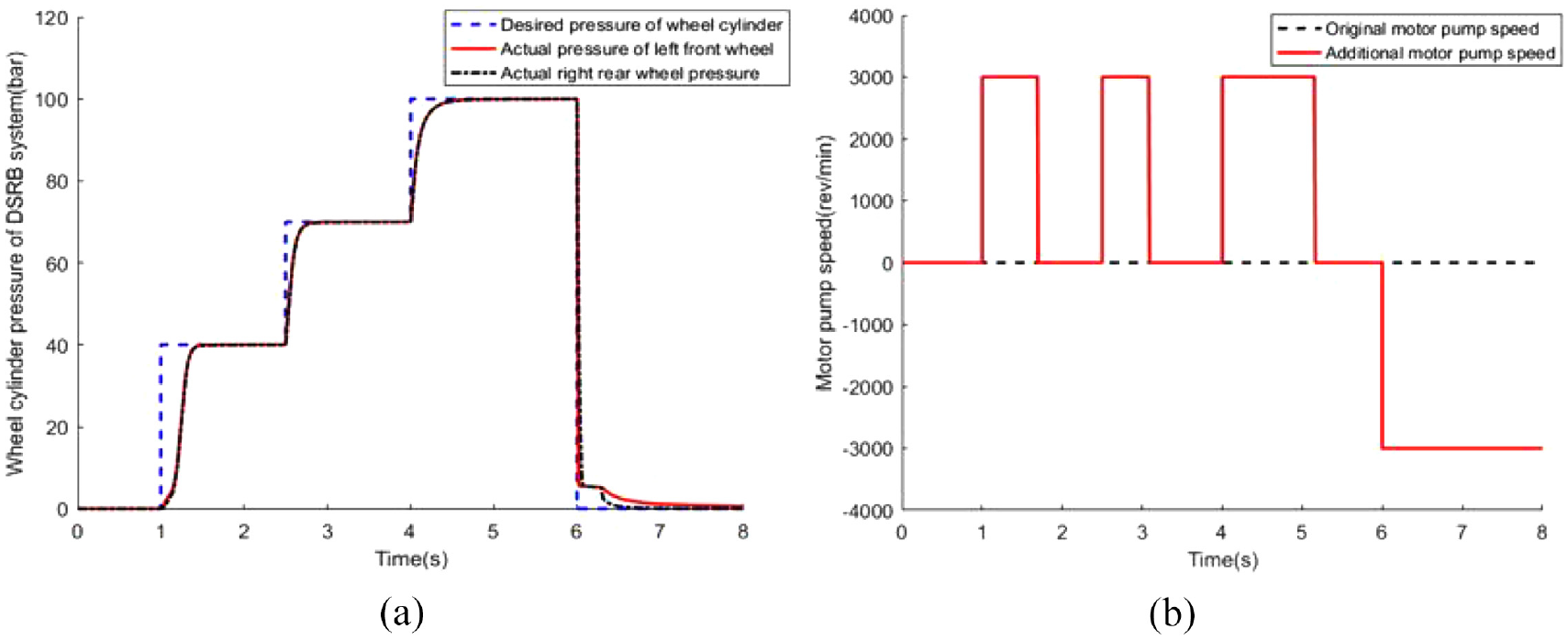
Complete failure condition: (a) brake pressure of wheel cylinder of DSRB and (b) motor pump and additional motor pump signals.
As shown, the pressurization speed of DSRB is still fast at 1, 2.5, and 4 s under complete failure condition, which remains stable within about 0.4 s. Meanwhile, the DSRB depressurizes rapidly at 6 s, and remains stable within about 0.4 s. Under complete failure condition, good braking efficiency and certain braking deceleration are still possessed by the DSRB. The dual motor design can actively pressurize the wheel cylinder in the case of the original motor failure of the system, and the design of the balance valve can replace the function when the oil inlet or outlet valves of the system fail, so that the DSRB system can normally realize the demand of pressurization and pressure reduction.
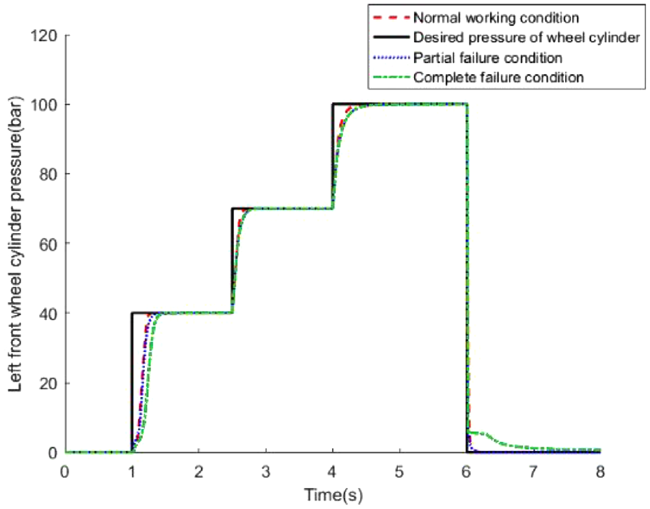
In conclusion, the wheel cylinder pressure control effects of DSRB are compared under normal working condition, partial failure condition and complete failure condition. Taking the left front wheel as the research object, the wheel cylinder pressure control under three working conditions is presented in Figure 12.
Pressure of left front wheel before and after failure.
Figure 12 shows that DSRB system can realize rapid adjustment of wheel cylinder pressure under partial failure condition or complete failure condition. Also, good braking efficiency and certain braking deceleration are still possessed by the system. When the oil inlet valve corresponding to the left front wheel fails, the pressurization speed of DSRB does not decrease significantly compared with the normal working condition. It has little impact on the system. When the DSRB system fails completely, the pressurization speed at 1 s is slightly lower than that under the normal working condition, only 0.18 s. Meanwhile, it has no great difference from the pressurization speed of EHB system under normal working condition.
Four-wheel model verification
In order to verify the reliability of the simulation effect of the simplified model, the DSRB system is further simulated without any simplification. The DSRB system model is shown in Figure 13.
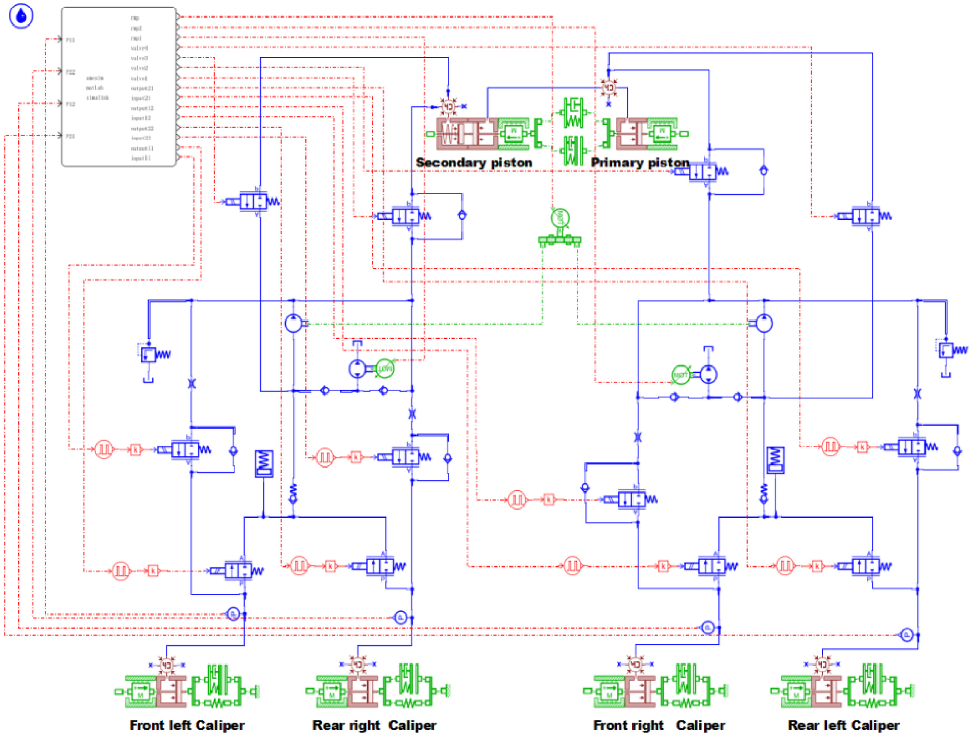
Four-wheel model of DSRB system.
Figure 14 shows that the pressurization speed of the system is generally fast. In the initial stage of pressurization, the pressurization speed is slightly slow due to the effect of system pressure building, and the pressurization time is about 0.3 s. Then, the pressurization speed is faster and remains stable within 0.2 s at 2.5 and 4 s. The decompression speed is very short and keeps stable quickly at 6 and 9 s. And the boosting speed slows down again, which is due to the fact that it takes a certain time for the additional motor pump to transition from positive to reverse at 7.5 s. It is verified that the simplified two-wheel model of DSRB system can show the good pressure following efficiency and redundancy of DSRB system.
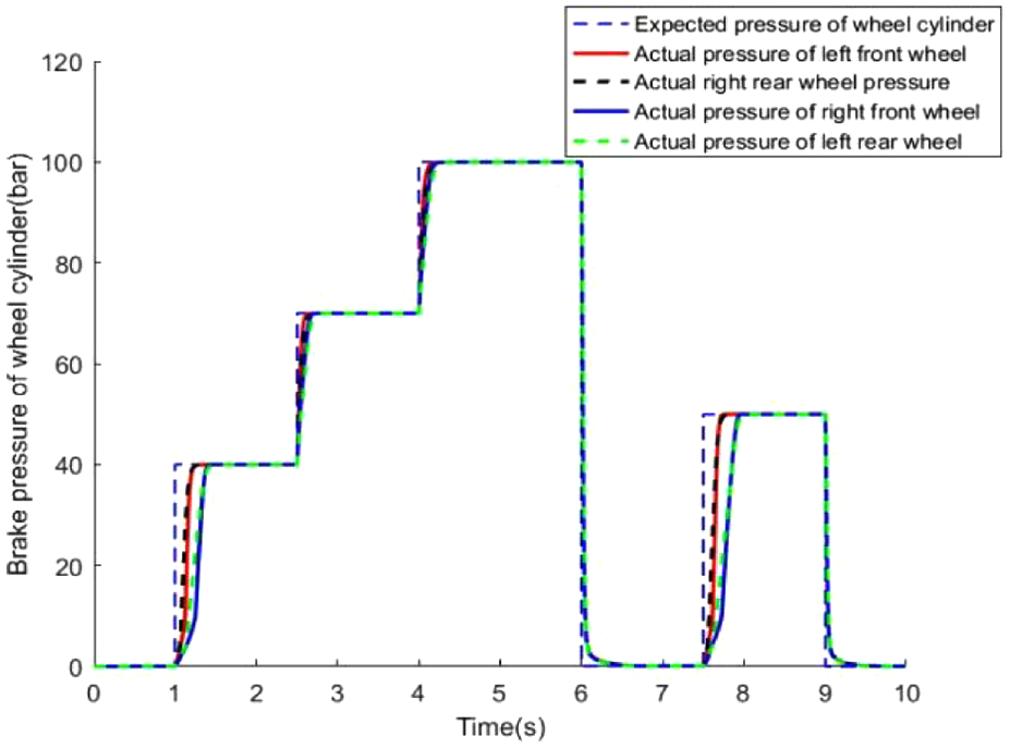
Simulation curve of four wheel cylinder braking pressure.
Therefore, the wheel cylinder pressure control algorithm based on PID control can quickly and accurately regulate the wheel cylinder pressure of DSRB system, and make it change with the expected pressure of wheel cylinder.
Conclusion
In this research, a novel dual-source redundant braking system was developed. Good braking efficiency, boosting speed and pressure regulation accuracy are available in DSRB even under the condition of partial failure or complete failure. Also, it does not need the function of the booster mechanism in all working conditions. Furthermore, the wheel cylinder pressure of DSRB system is accurately regulated by PID control algorithm. And the co-simulation was implemented to verify the accuracy and reliability of the braking efficiency of the DSRB. The result showed that the DSRB can quickly and accurately follow and respond to the desired wheel cylinder braking pressure under normal working condition, partial failure condition and complete failure condition. Therefore, the DSRB system with good braking efficiency has redundancy, reliability and certain fault tolerance.
Footnotes
Appendix 1
Appendix 2
Declaration of conflicting interests
The author(s) declared no potential conflicts of interest with respect to the research, authorship, and/or publication of this article.
Funding
The author(s) disclosed receipt of the following financial support for the research, authorship, and/or publication of this article: This project is supported by the National Natural Science Foundation of China (51775247, 52172346, U20A20333, 51875255, U20A 20331, 52072160), Key Research and Development Program of Jiangsu Province (BE2020083-3, BE2019 010-2), Six Talent Peaks Project of Jiangsu Province (2018-TD-GDZB-022).