
Abstract
Anti-coning brake discs are known for their superior NVH characteristics when compared to other disc designs, but also for poorer heat dissipation. Cooling characteristics of such a disc design are studied numerically and experimentally on a specially developed Thermal Spin Rig. The disc is installed inboard on a high-performance off-road vehicle, with portal axles and wheel drives, resulting in nearly fourfold higher disc rotational speeds in comparison to the wheel speeds. Being exposed to the free-flowing air and rotating much faster makes this application well worth the attention and deeper study in terms of disc cooling. Computational Fluid Dynamics (CFD) analyses show a detailed distribution of air velocities and pathlines, temperatures, pressures, and convective heat transfer coefficients. The results are all very coherent, conveying very useful information, both qualitatively and quantitatively. Their cumulative effect has been successfully validated by comparing the CFD predicted average convective heat transfer coefficients (hconv) with the experimental results obtained on the Thermal Spin Rig, in a controlled environment. CFD results show to be very close to average hconv values calculated from measured cooling curves. The agreement is very good for the wide temperature and speed range. The overall relative differences are under 5%, and in most cases under 3%, except for the low disc rotation speeds, which show a maximum relative difference of 12.5% calculated at 200 rpm, for the disc heated to 300°C. Such outcomes give confidence in the CFD results for future work in both disc design and vehicle installations.
Background
Even though they are exposed to high mechanical and thermal loading, brake discs are expected to have high reliability and long service lives, all at very low manufacturing costs. Brake discs must have good heat dissipation and Noise Vibration and Harshness (NVH) characteristics. These requirements led to the development of different disc designs and associated features, most notably anti-coning disc designs (also called front-vented). This type of disc cones much less under thermal loading (expansion), leading to more uniform interface pressure distributions and a more even wear of the disc and pads. 1 Consequently, this disc type has superior NVH characteristics. However, in addition to higher manufacturing costs and higher disc stresses compared to a traditional brake disc, a major drawback of this design is related to its inferior convective heat dissipation characteristics. 2 The airflow entering ventilation channels of an anti-coning disc is indeed obstructed when compared with a standard (back-vented) disc. Ambient air is drawn into the ventilation channels axially, with the access being limited to a narrow circular section (gap) between the top hat outer diameter (OD) and the disc inner diameter (ID). Furthermore, the airflow needs to turn 90° after entering in axial direction, to flow in radial direction through the disc ventilation channels, as shown in Figure 1 for instance, and finally be expelled at the disc OD. Most disappointingly, convective cooling cannot be significantly improved in this disc type by installing flow-promoting devices at the front of the disc. Such devices (scoops, plates, ducts, etc) can only be installed within the vehicle envelope or under it, and consequently, only increase the airflow to the disc inboard face. This disc is however drawing the air from the outside, where installation of similar devices is not possible.
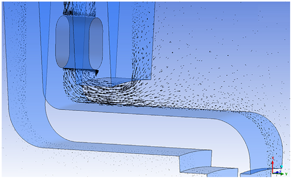
Airflow in a disc ventilation channel, flowing from an axial to a radial direction.
In more recent times, with the increased wheel sizes in passenger cars, space has been freed to instal larger discs, with larger OD but also larger ID. This extra space between top hat OD and disc ID has enabled the design of a swan neck’ transition shape between the top hat and the outboard disc friction face. This feature has radial elasticity, allowing freer disc expansion, and can considerably reduce coning. As a result, the NVH characteristics of swan-neck type discs approach those of the anti-coning disc types (as displayed in Figure 1), but have better cooling characteristics.
In addition to different disc types available, brakes, including discs brakes, can be installed outboard in vehicle wheels, inboard at the exit from the differential, or integrated with the transmission system. In the past, inboard disc installation has been favoured by several vehicle manufacturers (e.g. Jaguar, Citroen, etc.), as it reduces unsprung mass and lowers the load on suspension components during braking, as well as having an influence on the vehicle’s anti diving characteristics. However, over the years, in particular with the introduction of anti-locking brake systems (ABS), inboard disc installations have been mostly abandoned. The inboard disc installations are nowadays relatively rare, except for specific applications. One of these is in de Dion suspension systems (axles), where installation of inboard brakes can substantially simplify the suspension design by omitting the linkages to counterbalance braking torques. In such inboard brake installations, braking torque is transferred by the driveshaft from the brake to the wheel. As the driveshaft is torsionally relatively flexible, torsional vibrations can be a problem and such installations are known to be prone to brake judder. Consequently, a disc design with the best possible NVH characteristics is needed, which makes anti-coning disc design an obvious choice. Lower cooling characteristics of such a design (in comparison with standard and swan neck types) are not a considerable drawback, as the discs are directly exposed to airflow and not ‘nested’ within the wheel cavity.
The particular disc investigated here is mainly for a heavy duty vehicle which has a de Dion suspension system and portal-type axles with wheel (axle) drives, as shown in Figure 2. There is an increasing ground clearance and the driveshafts and discs rotate faster than the wheels. With a wheel drive ratio of 3.73, the discs rotate at nearly 2000 rpm at a vehicle maximum speed of 110 km/h instead of around 500 rpm at the wheels. Such a nearly fourfold increase in rotational speed considerably improves disc cooling, countering the inferior anti-coning disc convective cooling characteristics. In addition, the discs rotate in opposite direction from the wheels; the bottom of the discs OD (towards the ground) have a linear speed in the direction of travel, allowing the discs to get cool and fast flowing air, which further improves convective cooling.
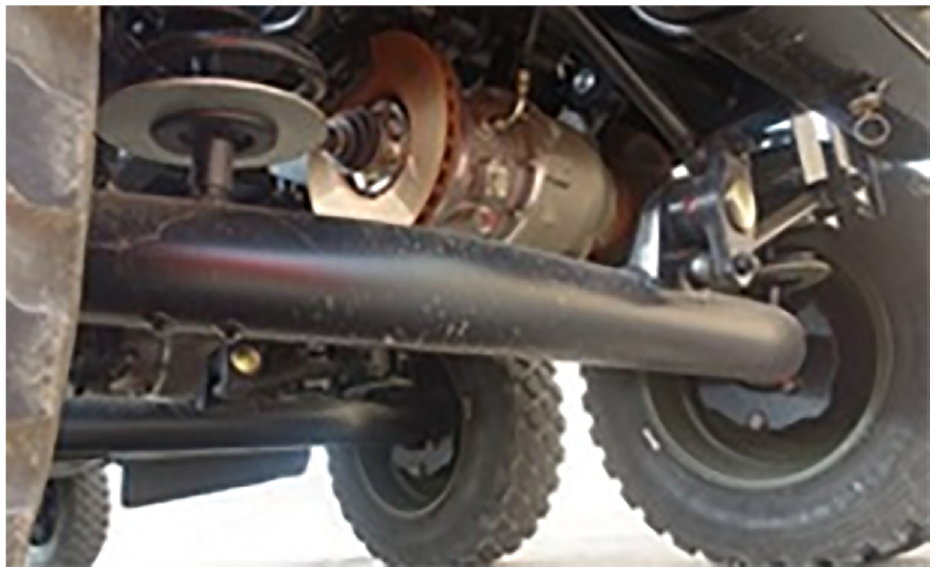
Brake disc installation.
Introduction – heat dissipation studies
Angelinas 3 conducted a detailed study of an anti-coning commercial vehicle (CV) brake disc and showed that an increase of the circular gap between the top hat OD and the disc ID could successfully increase the airflow and improve disc cooling. The author also showed that for the specific CV disc studied, additional problems in low convective cooling arise at the air exit from the ventilation channels, due to the small distance between the disc OD and the wheel rim ID. This situation could be improved by widening the circular gap that is, by reducing the disc OD, as the wheel diameter cannot be changed. Computational Fluid Dynamics (CFD) analyses from Angelinas 3 led to practical disc modifications, and the findings were experimentally verified. In principle, by increasing the disc ID and reducing its OD, the main swept radius can be kept unchanged, hence the nominal disc torque is not affected. However, there is an inevitable reduction of the disc thermal capacity due to the reduced mass (for the unchanged disc thickness). The risk of surface thermal damage is also increased due to a smaller (narrower) friction area. 3
Heat dissipation can follow three different modes: conduction, convection, and radiation. A detailed study of all heat dissipation modes for a heavy commercial vehicle brake disc was presented by Voller et al. 4 Experimental investigations were conducted on a specially developed Spin Thermal Rig, along with numerical studies based on Finite Element Analysis (FEA) and CFD. For conductive heat dissipations, the authors showed that the average contact pressure between the disc and the wheel carrier varied between 10 and 50 MPa and the conductive heat transfer increased linearly with the increase of contact pressure, giving a very useful universal formulae for calculating conductive heat transfer coefficient as a function of interface pressure. For radiative heat dissipation, the authors showed that between 20°C and 200°C, emissivity values of 0.2 and 0.9 could be assigned to a new machined disc brake surface and a corroded disc surface, respectively. The experimental studies of convective heat dissipation from Voller et al., 4 included the disc only, and the wheel assembly (including the disc brake, the wheel, and the wheel carrier), showing detrimental influence of the wheel on air supply and hence disc cooling. Convective heat transfer coefficients were derived from measured cooling curves.
Sakamoto 5 used an analytical approach to evaluate the convective heat transfer coefficient on local surfaces (ventilation channels and friction surfaces). He showed that the cooling rate parameter could be used to evaluate an overall convective heat transfer coefficient. He also demonstrated that the largest the cooling rate, the greater the cooling performance of the disc at a lower maximum temperature.
As ventilated brake discs give advantages in terms of heat dissipation, many studies have looked at the airflow behaviour through different rotor passage shapes. Johnson et al. 6 studied the flow inside the rotor passages of a vented brake disc by using particle image velocity (PIV) techniques. It was shown that the highest turbulent kinetic energy was located in the middle of the air passage regions; this is due to recirculation of the fluid on the internal surfaces of the vent passages. This research provides useful information as it indicates where the geometry can be improved to maximise the cooling effect of the disc.
One way of improving a common vented disc brake was proposed by Daudi, 7 through implementing additional fins in the original rotor configuration, and tilting them to achieve more airflow through the disc. It was estimated that the new configuration of the rotor was able to achieve 34.8% more airflow than the standard configuration, and that this improvement was made possible as recirculations were reduced through alternating small and short fins.
The airflow behaviour was also investigated by Cheng, 8 where a parametric study was performed to establish the best configuration for a vented brake disc. The study was based on the assumption that the higher the number of vanes, the better the cooling performance of the rotor. The author found out that the optimum number of vanes strongly depends on the rotor diameter, the flow passage width, and the vane thickness. An increase of the number of vanes provides a higher pumping effect but can also cause blockage events to the airflow. It was also shown that the heat transfer coefficient, which is mainly related to the airflow velocity, is a function of the cooling surface area.
CFD was effectively used by Barigozzi et al. 9 who investigated the aero-thermal phenomena inside a backward curved blade and on multiple pin-based configurations. He demonstrated that the backward curved brake disc flow behaviour is close to that of a centrifugal blower, which means that such a disc is characterised by a high mass flow rate exiting the rotor passages. The same findings were however not obtained for the pin-based configurations, as the flow pattern was complex and produced larger turbulence intensity values.
A CFD study on six different disc brake configurations was performed by Reddy et al. 10 A rotating frame of reference approach was adopted, and the fluid was assumed to be an incompressible ideal gas. Based on their numerical results, the authors proved that ventilated pillared rotors could be used for modern high-speed applications, as the heat dissipation rate from the surfaces of the rotor was the highest one compared to the other configurations investigated.
Topouris et al. 11 investigated experimentally the heat dissipation from stationary discs. Their results agreed well with CFD simulated results, although differences were more pronounced for ventilated discs. Out of the four designs investigated, the disc with radial vanes showed the highest convective heat dissipation coefficient and the solid disc the lowest.
Palmer et al. 12 studied a pin-vented disc brake, evaluating the effects of modifying the pin geometries. The authors altered both the upper and lower pin rows with four NACA aerofoils. For each of them, the ratio between thickness and chord length was modified, however keeping a constant chord length and a zero angle of camber (i.e. symmetrical pins). The analysis was used to evaluate how the mass flow and heat transfer rates changed when modifying pins dimensions. Results showed a mass flow rate decrease when the width of the pins was increased, due to blockages created by stagnation zones in the rotor passage. When the first row of pins had a particular width, a Venturi” effect acted on the inlet flow, producing flow acceleration. This resulted in a more efficient heat transfer coefficient. It was shown that a 14% increment of mass flow rate and 6% increment of heat transfer rate was achievable by modifying the pin thickness of one row only.
As pointed out in Güleryüz and Karadeniz, 13 most studies reported in the literature deal with brake rotors of passenger and high-performance cars, but only a few studies are related to heavy-duty vehicles. Previous work on heavy-duty vehicles was considered in Voller et al., 4 Galindo-Lopez and Tirovic, 14 Tang et al., 15 Stevens and Tirovic, 16 and Tirovic and Stevens 17 for instance, and only Tang et al. 15 and Stevens and Tirovic 16 provided insights on the CFD aspects.The current study therefore aims at studying further the heat transfer of anti-coning brakes for heavy-duty vehicles, using CFD approaches.
Brake disc characteristics
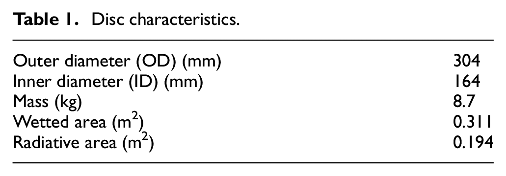
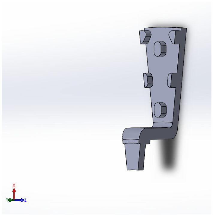
The brake rotor considered in this study was shown mounted on the vehicle in Figure 2. This rotor is an anti-coning ventilated brake disc made of grey cast iron and composed of a series of four-pin rows. Figure 3 presents the CAD model displaying ventilating system areas, that is, the channels and pins. The characteristics of this disc are summarised in Table 1.
Disc characteristics.
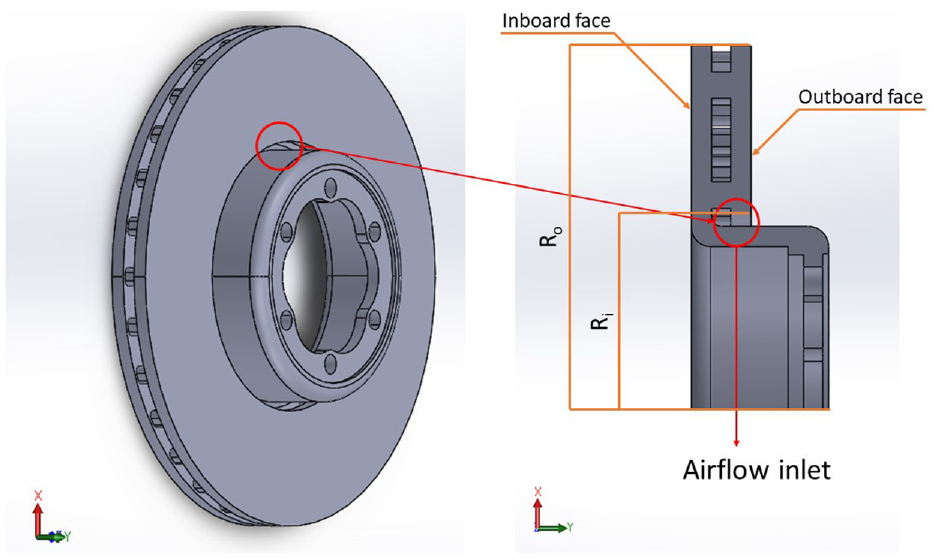
Ventilated brake disc model.
The gap between the disc top hat section and the outboard face, as seen in Figure 3, creates an airflow inlet. Air therefore flows into the disc ventilation system, entering the channels between the pillar labyrinth and exiting at the disc OD. The outboard and inboard faces highlighted in Figure 3 show where the brake pads rub onto the disc, generating friction forces and heat. Due to the presence of pillars and the absence of radial vanes, this brake disc does not exhibit high flow rates, even for an anti-coning disc type. However, as explained previously, the disc rotational speed is nearly four times higher than the wheel speed, and the disc is exposed to cross airflow. Furthermore, pillars used instead of vanes also have positive effects for avoiding NVH issues. In heavy-duty brake applications, these features tend to create additional but smaller hot spots, in comparison to vanes, which create fewer but larger hot spots which increase the probability of judder occurrence. This has been well studied and clearly presented in Tirovic and Stevens. 18
Modelling conditions, fluid domain and mesh
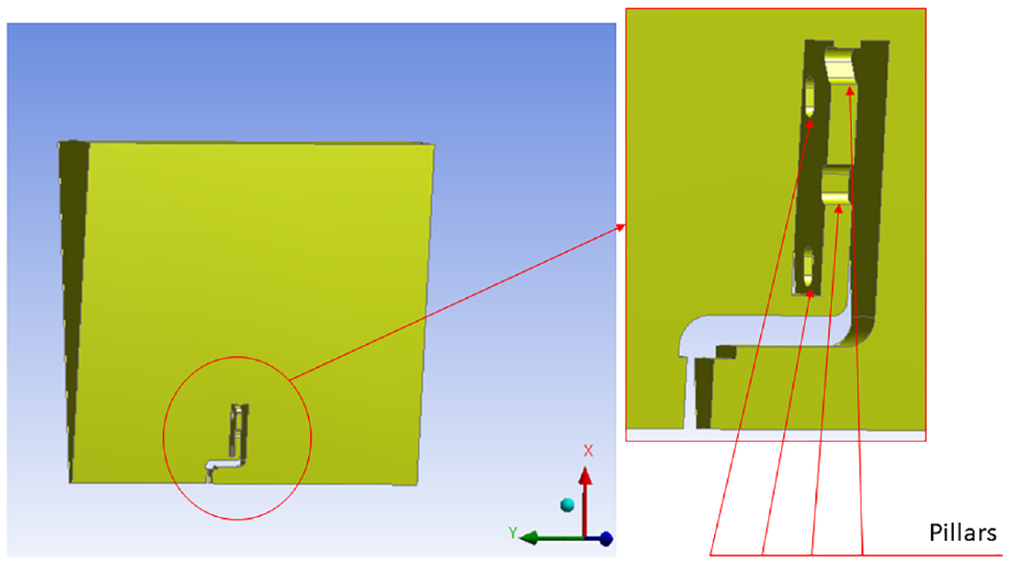
The disc was assumed to rotate in still air, without any obstructions. To obtain the heat and flow solution through CFD, a computational domain was created around the disc, a 0.5 m long cylinder of 1 m diameter. This external domain was found large enough to prevent any boundary effects on the disc. Periodic boundary conditions were applied to reduce the simulation time and resources, similarly as performed by Galindo-Lopez. 19 Only a 12° angular section of the disc was considered and simulated, as shown in Figures 4 and 5.
A 12° section of the disc (outboard face removed).
Air domain configuration.
The mesh was generated with ANSYS Meshing 19.1. As the cooling characteristics of a brake disc strongly depend on the airflow behaviour inside its rotor passages, the mesh was refined on the disc surfaces and inside the vane.
Boundary conditions
Five distinctive boundaries were defined: two periodic faces, an opening region, the shaft wall, and the disc wall, as shown in Figure 6.
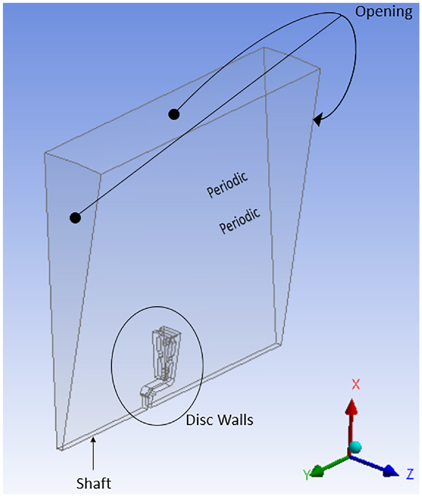
Boundary conditions.
The shaft and disc were considered as rotating smooth walls, thus neglecting any potential influence of the wall roughness on the turbulence and the wall heat transfer coefficient calculation. A no-slip condition was specified at the disc walls, and a temperature of either 200°C or 300°C was assigned to the disc surfaces; such temperatures are common in the brake operation. A no-slip condition was also applied on the shaft surfaces, considered adiabatic. An opening type condition was applied to the front, back and top surfaces of the computational domain, which is equivalent to a pressure outlet type boundary condition sometimes seen in other CFD software. This option can be used only when a subsonic flow is present and allows the study of the flow entering and leaving the domain. Finally, periodic boundary conditions were applied on both sides of the 12° angular sector considered here.
Model set-up
The steady solver of ANSYS CFX 19.1 was selected, and a rotating frame of reference methodology was applied for the disc to rotate around the y-axis, at an angular velocity
The two-equation standard k-
A second order discretisation was considered for all equations to ensure a good accuracy of the results apart from the
The convective heat transfer coefficient h

which is the ratio between the heat flux q and the difference between the wall temperature T
Mesh independence study
A mesh independence study was carried out to ensure that the CFD results do not depend on the mesh density. This study was performed considering a disc temperature of 200°C, the external environment at 20°C, and a rotational speed of 200 rpm. The tetrahedral meshes generated for this study ranged from around 155,000 to
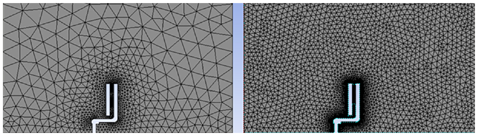
Examples of meshes generated for this study. Left: 155,000 elements; Right: 1.5 million elements.
As can be seen in Figure 8, the

Mesh independence study – HTC.
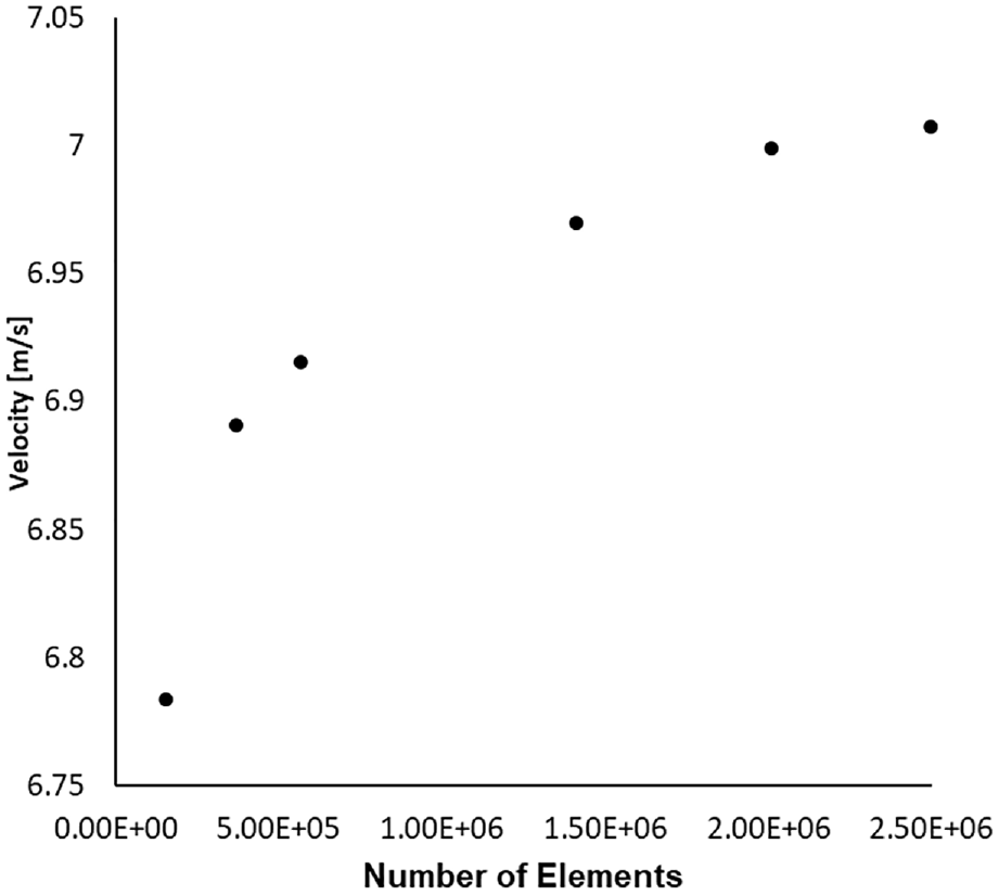
Mesh independence study – mean velocity through brake disc enclosure.
Airflow analysis
Figure 10 displays the pathlines of the flow from the ventilation channels and around the disc heated at 200°C, in still air, at 600 rpm, for the stationary frame of reference.
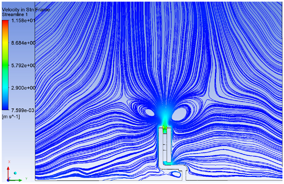
Airflow behaviour, disc at 200°C and 600 rpm.
The disc works as a fan, drawing the air from the gap between the outboard face and the hat of the disc, and expelling it as a free jet at the outer diameter. Two main recirculation zones are present at the exit of the vane, which is in agreement with the experimental observation from Johnson et al. 6
Vector plots were also plotted on a plane created in the middle section of the ventilation channel, as shown in Figure 11 for 200 and 2000 rpm, with the disc rotating anti-clockwise. The effects of the pillars on the flow behaviour can be seen, causing recirculations, in the top right hand sides, and stagnation regions in the top right corners, that is on the trailing sides. Similar flow features were obtained by Reddy et al., 10 who studied the effects of different pillar designs on the flow behaviour in the ventilation channel of a typical passenger car.
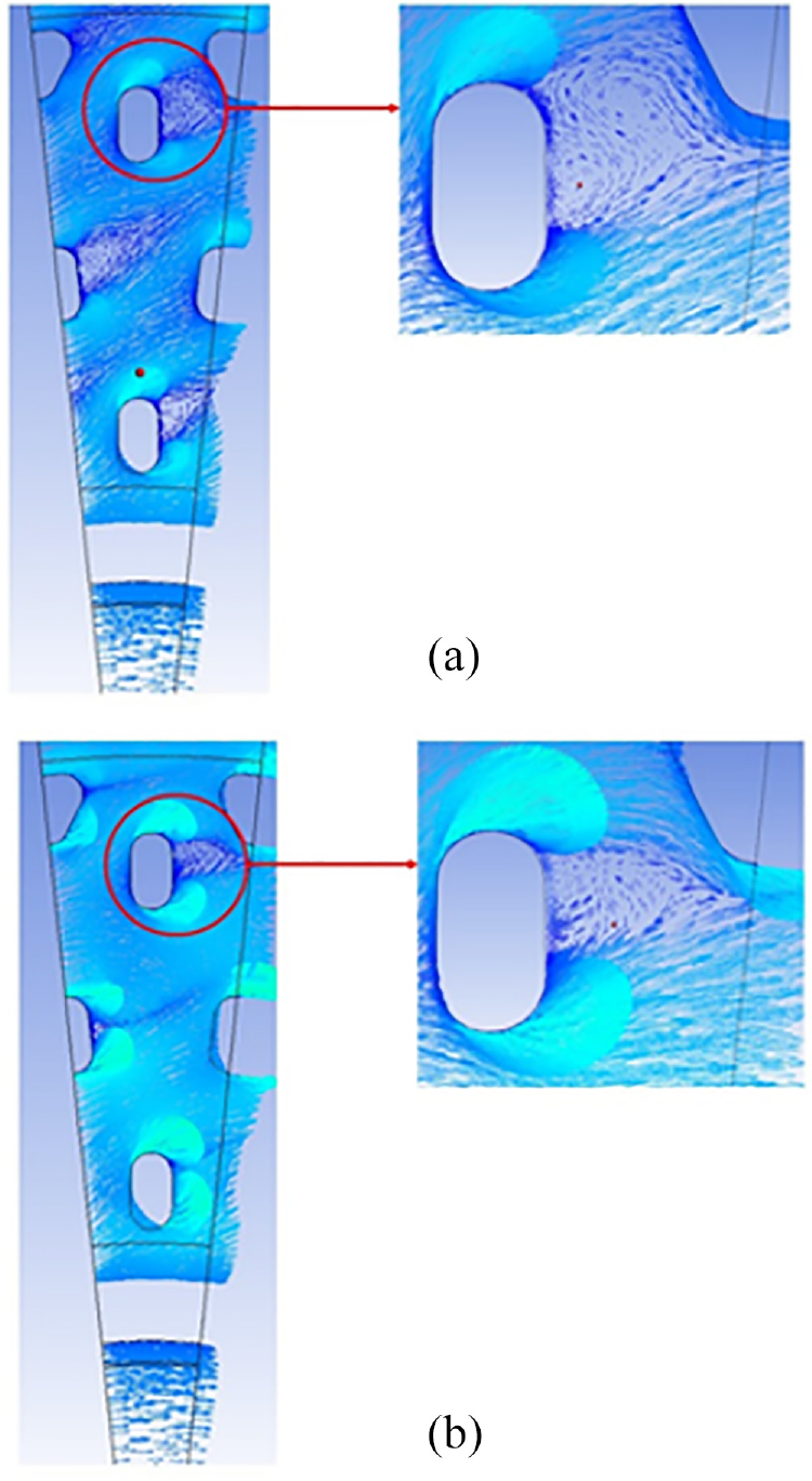
Mid-plane velocities at 200°C: (a) 200 rpm and (b) 2000 rpm.
The velocity of the flow into the ventilation channels is lower than the flow in a straight radial vane, for instance. Reddy et al. 10 indeed demonstrated that the flow rate in a straight radial vane was increased by 30% at 1600 rpm compared to a diamond vane design, which is similar to the radial vane considered here. For the radial vane design, outlet velocities of 0.47 and 1.31 m/s are obtained at 600 and 1600 rpm, respectively. Reddy et al. obtained a higher outlet velocity of 2.85 m/s on their straight radial vane brake disc. The pillared disc therefore provides low heat dissipation.
At high rotational speeds, for instance for 2000 rpm, a decrease of the recirculation was seen in Figure 11(b), which induced an increase of the overall airflow velocity within the channels, and therefore induced an increase of heat transfer rate performance.
Mass flow rate
An increase of the rotational speed increases the rate of airflow. To study this further, the mass flow rate was extrapolated and different rotational velocities and temperatures of the disc were compared. Note that for post-processing purposes, a plane was defined close to the exit of the ventilation channel (displayed in Figure 12) to evaluate such mass flow rate from the ventilation channel.
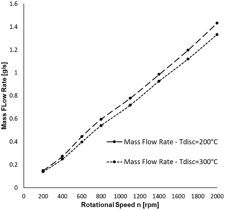
Mass flow rate comparison with an increment of rotational velocity and/or an increment of the disc temperature.
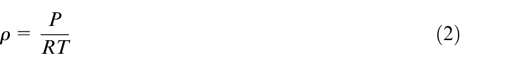
A constant disc temperature of 200°C was initially applied, and the rotational speed gradually increased from 200 to 2000 rpm, in 200 rpm increments. The disc temperature was then increased to 300°C throughout the rotational speed range. The corresponding mass flow results are shown in Figure 13, where, as expected, a higher air mass flow rate is associated with a lower disc temperature. This is related to the air density and can be established through the gas law:
Static pressure contours plot – disc at 200°C and 600 rpm.
where
Pressure
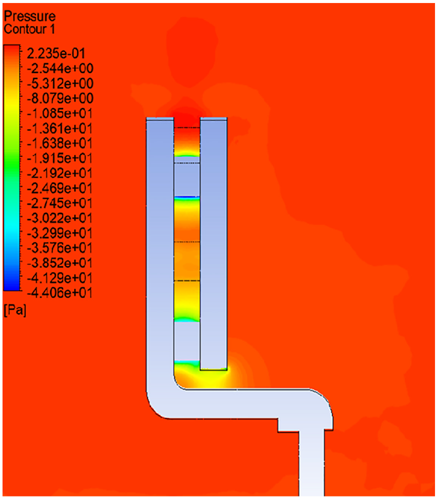
The static pressure contours plot is shown in Figure 14, in the YX plane, for the disc at 200°C, rotating at 600 rpm. As expected, the highlighted low-pressure region was identified at the air inlet, and in the ventilation channels.
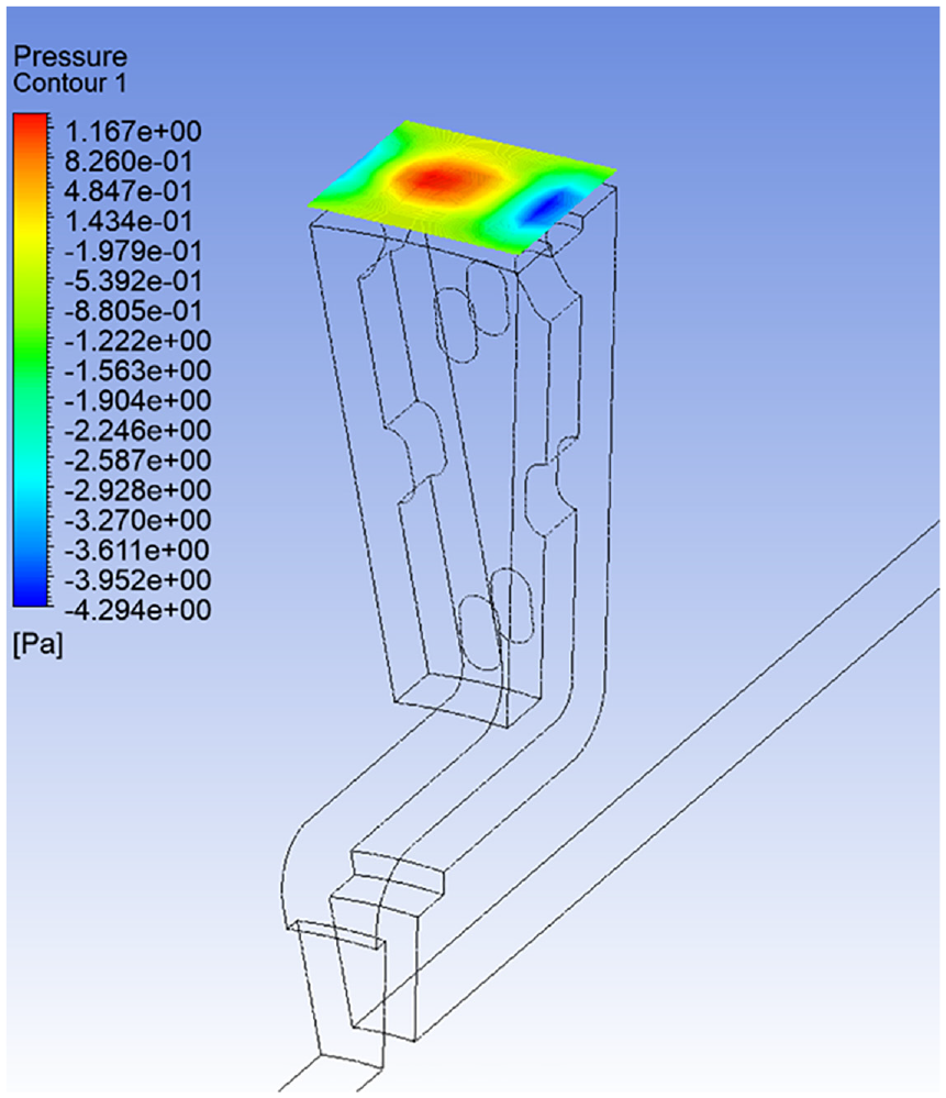
Static pressure contours plot at the outlet section of the ventilation channel (YZ plane) – disc at 200°C and 600 rpm.
Due to the difference of pressure between the inside and outside parts of the ventilation channel, a pumping effect is created, which is coherent with the previous observations for the pathlines and velocity vectors shown in Figures 10 and 11.
The static pressure contours plot is also shown in a YZ plane located 2 mm above the outlet section of the vane, see Figure 12. A high-pressure zone is seen in the middle of the plane, which corresponds to a low flow velocity at the exit of the ventilation channel. Low pressure regions are present on the sides, corresponding to regions displaying high flow velocity values.
Figure 15 shows the static pressure distribution inside the ventilation channel for the same conditions (disc at 200°C, rotating at 600 rpm), with overall low pressure values present compared to the external environment; this further confirms the pumping effect of the disc. For the counter-clockwise rotation of the disc, high pressure zones are found attached to the left sides of the pillar surfaces, indicating stagnation regions.
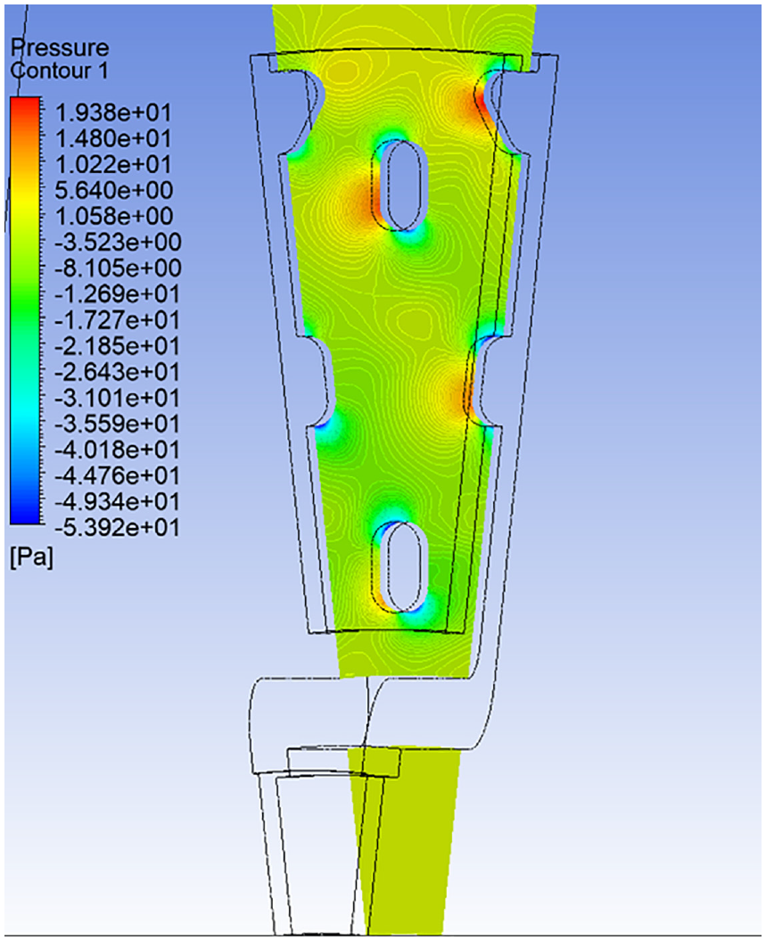
Static pressure contours plot inside the ventilation channels – disc at 200°C and 600 rpm.
Convective heat transfer coefficient
At the mid-section of the ventilation channel, high air temperature values are assumed present relative to the external environment. This condition is mainly associated with an overall low airflow velocity, which does not allow the disc to dissipate a high heat rate.
Figure 16 obtained for the disc at 200°C, rotating at 600 rpm, shows higher air temperature values in flow recirculation regions, associated with low velocity values.
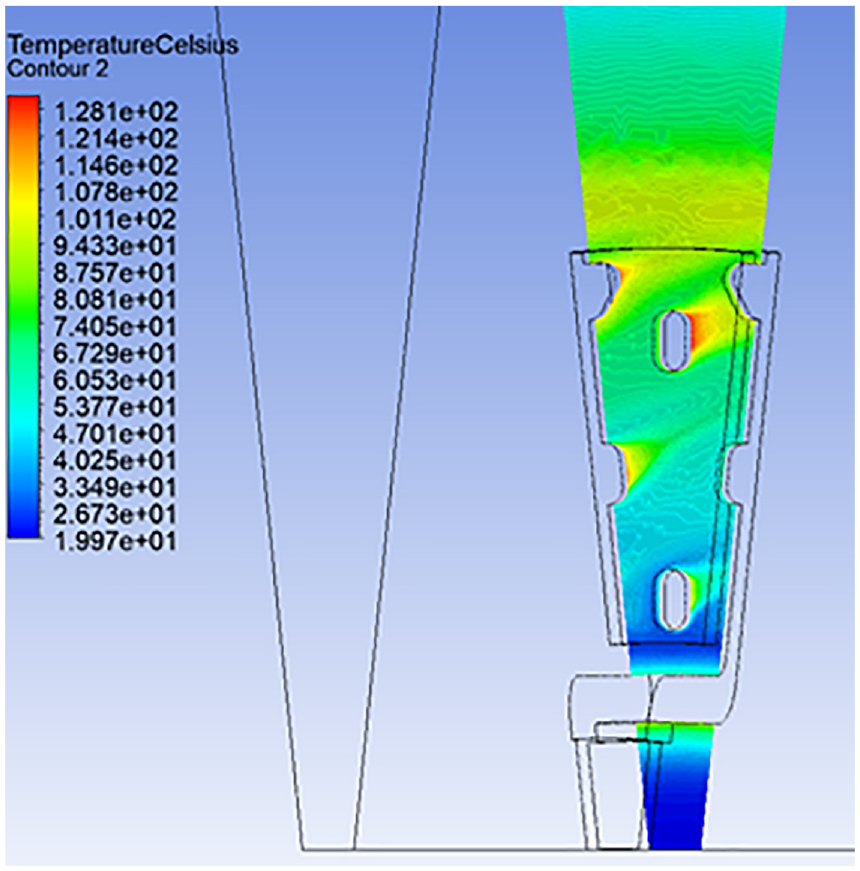
Air temperatures in the mid-section of the vane – disc at 200°C and 600 rpm.
To understand the effects of the flow on the heat transfer exchange,
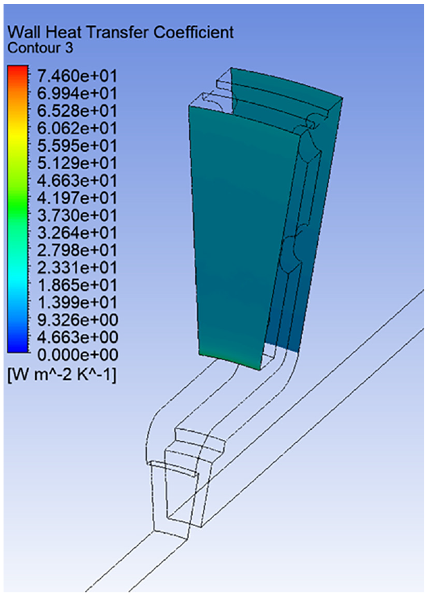
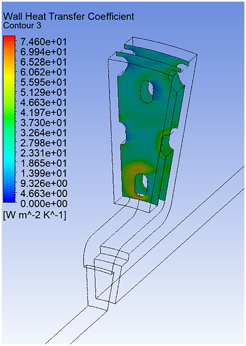
As shown in Figure 17, friction surfaces (outboard and inboard) display relatively low
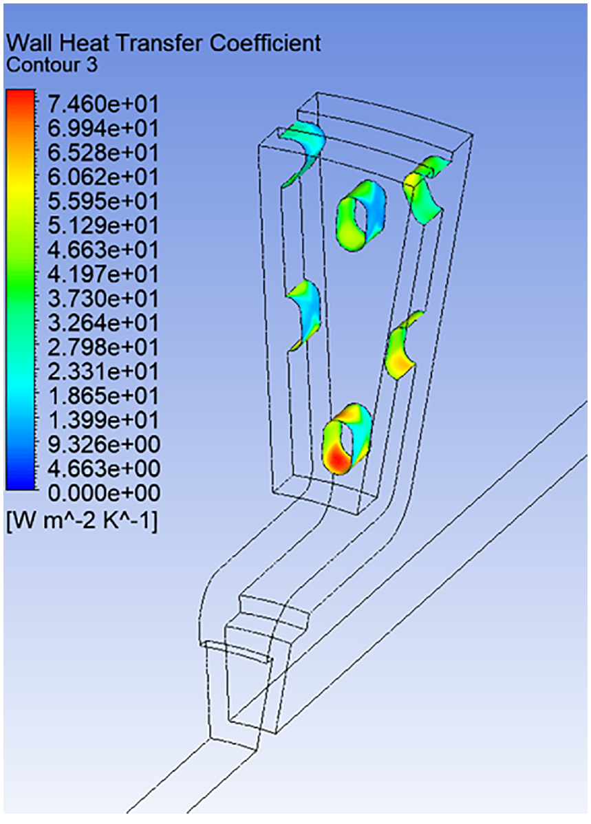
In contrast,
The
Figure 20 shows that, as expected, the convective heat transfer coefficient values increase with the disc rotational speed (denoted n). This result is in agreement with the previous mass flow rate analysis. Although the results highlight poor heat dissipation at low angular velocities, cooling performance improves much at higher rotational speeds.
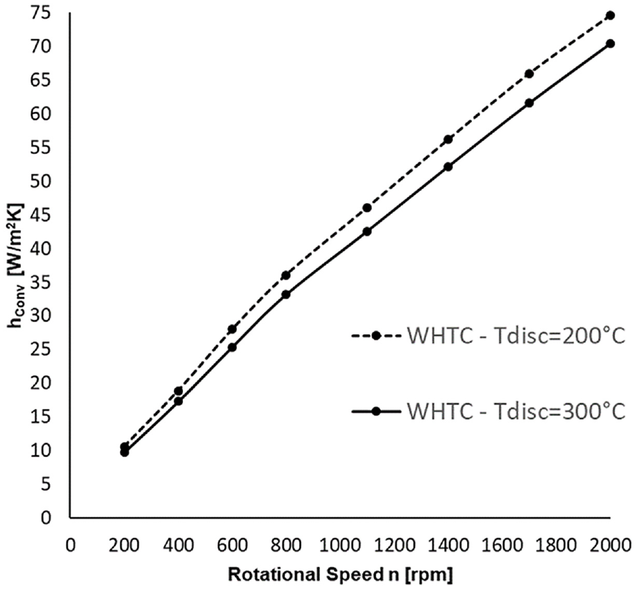
Figure 20 also shows that the heat dissipation is lower when the temperature of the disc increases, and the difference increases at higher rotational speeds.
Validation
To validate the numerical model, CFD-based heat transfer coefficient values obtained in this work were compared with experimental data generated on the same brake disc. 26 The experimental work was very extensive, covering a wide range of disc temperatures and rotational speeds. In addition to the tests conducted in still air, cooling tests were also performed in the flow channel for a combination of disc rotational speeds and cross airflow velocities. The test conditions included parallel and angular flows, see Figure 21 for schematics of the mounted disc at 0° and +10° inclinations.
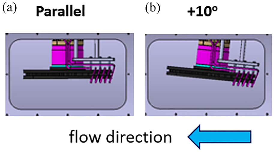
Disc mounted on the thermal spin rig: (a) parallel flow and (b) +10° angular flow.
The testing rig, development and general experimental procedure are presented in Tirovic et al., 27 however for a different disc design, with Gucci 26 detailing the actual test results. Figure 22 shows the disc mounted on the thermal rig, together with the induction heater coil employed to heat the disc, and the rubbing thermocouples used to measure the disc temperature. Convective heat transfer coefficients were extracted from the measured cooling curves, which were established by logging temperatures measured using six rubbing thermocouples. The disc was heated using an inductive heater, which provided uniform heat within the mass of the disc. During heating, the disc was rotated at about 100 rpm to ensure equal heating around the disc. When the temperature reached around 500°C, the heater was turned off and the disc rotation continued in order to soak in the heat and equalise the temperature over the entire disc. Finally, the rotation speed (and airflow speed for cross flow measurements) was brought to the desired level and cooling curves were recorded. Note that a soaking time of about 3 min is typically sufficient for equalising disc temperatures across the friction surface. If longer, the average disc temperature would drop, reducing the temperature range for calculating heat transfer coefficients. If the time is shorter, the temperature differences across the disc friction surface would be more pronounced and calculation less accurate.26,27
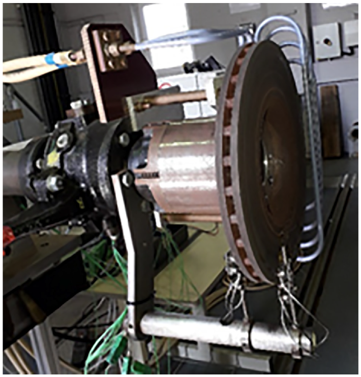
Disc mounted on the thermal spin rig.
All three modes of heat transfer were considered and accurately included in the calculations, with convective cooling representing a dominant heat transfer mode in most test conditions.
Figure 23 shows experimental and CFD values of
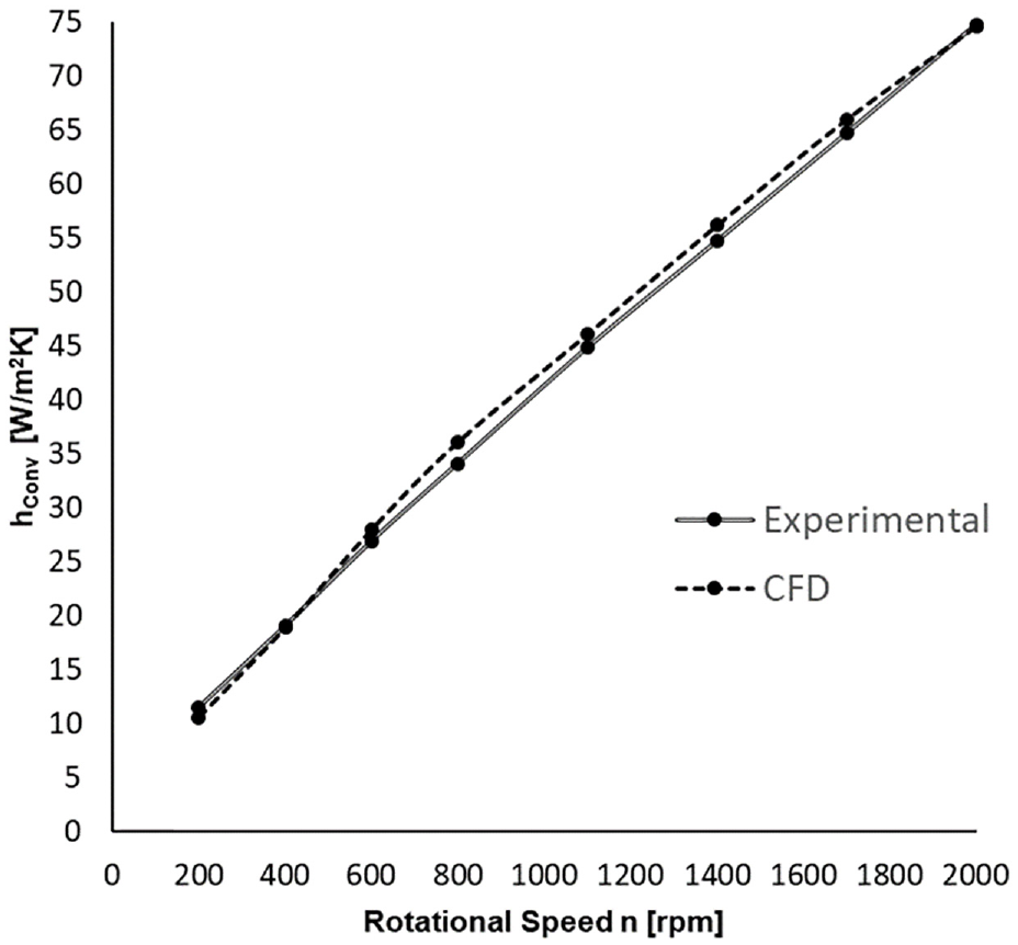
Experimental and CFD
It can be observed that the CFD-based results very slightly over-predict the measured values over most of the speed range considered, except for the minimum and maximum speeds, where the situation is opposite. The corresponding values are also included in Table 2, together with the calculated relative differences.
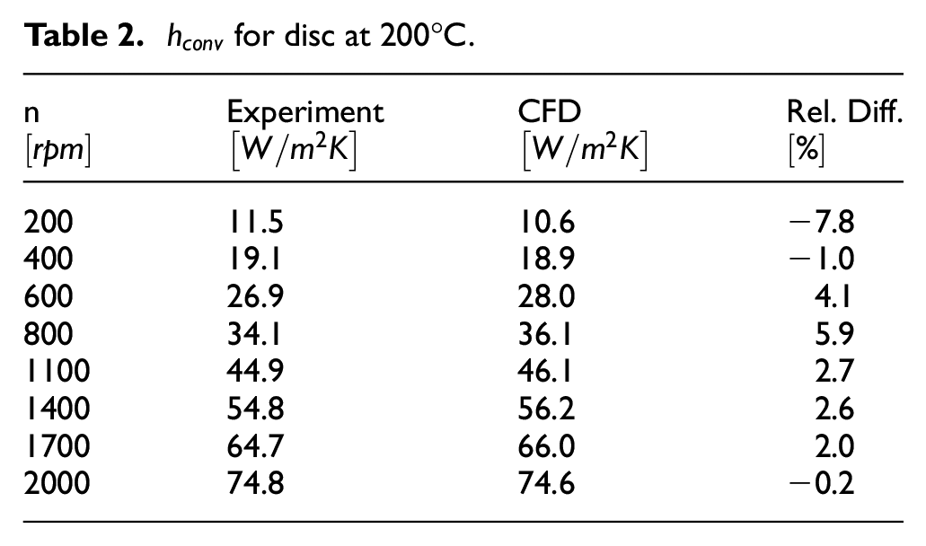
CFD results thus agree quite well with the experimental values through the speed range, with the differences being on average under 5%, and for most rotational speeds under 3%. The exception is obtained at 600 rpm, where the difference is 4.1%, 800 rpm with 5.9% difference, whereas the highest difference of 7.8% is obtained for the lowest speed of 200 rpm. At low rotational speeds, the flow might be predominantly in the laminar regime or in the laminar/turbulent transitional regime, which is not well handled by the standard k-
CFD and experimental data were also compared for a higher disc temperature of 300°C, as presented in Figure 24 and detailed in Table 3.
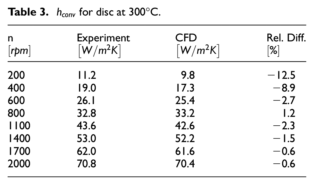
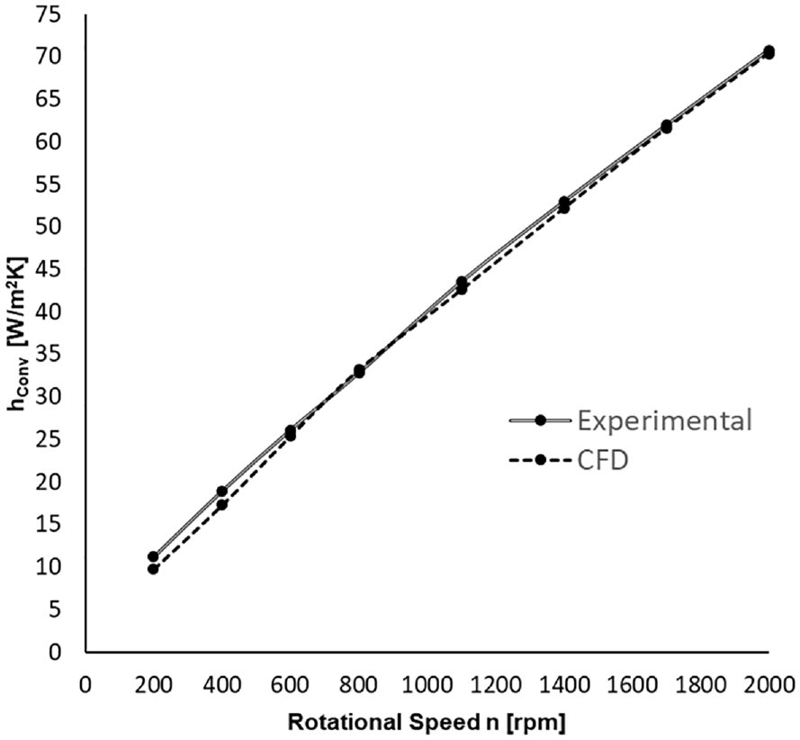
Experimental and CFD
As for the previous case at a lower disc temperature, the higher discrepancies are found at lower rotational speeds, with somewhat higher relative differences at 200 rpm (12.5%) and at 400 rpm (8.9%), with the differences for all other speeds being under 3%. Again, the overall discrepancy is under 5% but this time, the CFD-based
Conclusion
CFD helped in getting an insight into the airflow and heat dissipation from an anti-coning type brake disc used in heavy-duty vehicles, when rotating in still air. This type of brake disc is known for its superior NVH characteristics but inferior heat dissipation. CFD-based results provided a strong foundation for further analysis, and could help improve heat dissipation from this disc design.
Predicted distributions of pathlines, air velocities and temperatures, pressures and convective heat transfer coefficients, are all very coherent, conveying complementary information, both qualitative and quantitative. Within the scope of this research, it was not possible to validate all flow and heat transfer parameters but their cumulative effect has been fully and successfully validated by comparing the CFD predicted average convective heat transfer coefficients with the corresponding experimental results.
The tests were conducted in a controlled environment, on a special rig. The numerical results matched well the average
Such outcomes give confidence for future work in disc design and optimisation. Furthermore, a cross-flow could be introduced to investigate vehicle installations, and CFD simulations could be successfully employed for a better understanding and for improving disc installation in different vehicles. The experimental cooling results showed the importance of cross air velocities, which considerably accelerate disc cooling. For this particular vehicle (cf. Figure 2), inboard disc installation and wheel drives (having a 3.73 ratio) considerably improved cooling due to high disc rotational speeds (in comparison to the wheel speeds), and to the discs being exposed to the free-flowing air.
Footnotes
Appendix
Declaration of conflicting interests
The author(s) declared no potential conflicts of interest with respect to the research, authorship, and/or publication of this article.
Funding
The author(s) received no financial support for the research, authorship, and/or publication of this article.