
Abstract
Opposed-Piston, Two-Stroke (OP2S) diesel engine is a potential powertrain to achieve efficient and clean combustion. However, its non-uniformity of mixing and combustion restricts performance improvement. To solve this problem, this work proposed a lateral swirl combustion system (LSCS) for the OP2S diesel engine. Applying CFD simulation, this work studied the effects of different combustion chamber parameters on the mixing and combustion performance, power, and emissions of the LSCS of the OP2S diesel engine. Furthermore, the combustion parameters were optimized by sensitivity analysis and parameter normalization methods. The results show that the LSCS helps improve the non-uniformity of mixing & combustion of the OP2S diesel engine, accelerate burning, improve the power of the OP2S diesel engine and reduce soot emissions. Besides, under certain fuel supply conditions, it is necessary to make good use of the space of the axial and radial sections of the combustion chamber and make the convex edge height realize the split-flow effect. Therefore the performance of the LSCS can be improved effectively in the OP2S diesel engine.
Introduction
The energy crisis and environmental problems have prompted more intense competition in the traditional internal combustion engine industry. 1 This difficult situation has forced domestic and international research institutions to explore new power systems, and have successively planned development prospects for new power systems. By 2040, traditional engines still have an ample space for development but it requires further engine weight reduction to achieve the goal of energy-saving and emission reduction. 2 An opposed-piston, two-stroke (OP2S) diesel engine has attracted attention due to its simple structure, high power density, high thermal efficiency, and low heat transfer loss.3,4 Jean-Pierre Pirault and Martin Flint pointed out that compared with engines of the same volume, the inherent characteristics of the OP2S diesel engine show strong operating and cost advantages, which are very suitable for the future demand for high-performance engines. 5 Therefore, using new technology to research OP2S diesel engines has a good development prospect to overcome its disadvantages, to achieve high-efficiency and low-emission combustion.
The combustion system of opposed-piston engines adopts side-injection on the cylinder wall. Their combustion chamber is composed of the top surfaces of the intake and exhaust pistons and the inner wall of the cylinder liner. This combustion system results in non-uniformity of mixing and combustion, which will reduce thermal efficiency and increase emissions. To improve asymmetric mixing and combustion of opposed-piston engines, researchers focused on combustion systems of different types of opposed-piston engines. FEV company first developed a shell-shaped combustion chamber to promote fuel-air mixing through the high-pressure injection system. 6 In recent years, new types of opposed-piston engine combustion systems have emerged. Beijing Institute of Technology has developed a pit piston combustion system, in which an injector and a spark plug are arranged oppositely in the cylinder. 7 The combustion system realizes an asymmetric scavenging process through the pitted piston and enhances squish flow through the piston top to promote mixed combustion in the cylinder. Achates power company has developed a bowl-type combustion system. 8 The combustion system can generate squish flow by designing multiple squish areas on the crown of the intake and exhaust pistons. After the squish flow enters the combustion chamber, the arc surface of the top surface of the piston is used to promote the squish flow to roll, thereby accelerating the mixed combustion speed. 9 Ecomotors proposed a toroidal combustion chamber. 10 The combustion chamber is formed by an intake piston with a central convex area and an exhaust piston with a concave bowl in the middle, toward which fuel is injected.
These opposed-piston engine combustion systems mainly use the unique structure of the top surfaces of the intake and exhaust pistons and the spraying method of fuel to generate squish and tumble motions, accelerating the mixing and combustion. In essence, it is also a containment combustion system that uses the wall of the combustion chamber to confine air to the area where the fuel is sprayed. In addition, the interaction between the combustion chamber wall and the fuel can be used to improve mixing and combustion. This technology has been widely used in traditional engines, such as lateral swirl combustion systems (LSCSs), Deutz combustion systems, 11 and wave-piston combustion systems.12,13 The wave-piston combustion systems can enhance late-cycle mixing, reducing soot emissions and promoting thermal efficiency. 14 Some new combustion systems also appear. The innovative hybrid piston with some radial bumps was designed by Federico Millo et al. to achieve ultra-low soot emissions.15,16 However, this technology has not been studied on opposed-piston engines, as shown in Figure 1.
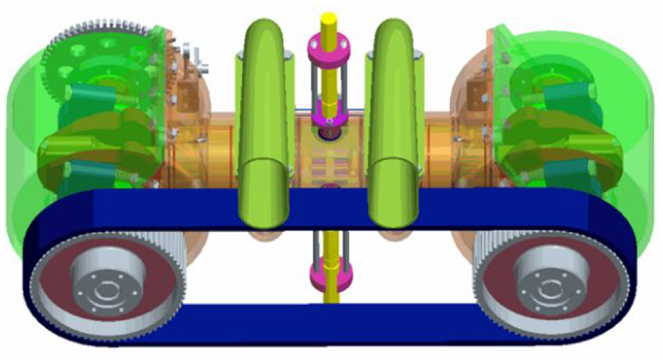
An OP2S diesel engine.
In this work, based on the mixing and combustion mechanism of the traditional LSCS, 17 combined with the characteristics of the OP2S diesel engine, a LSCS for the OP2S diesel engine is proposed, 18 as shown in Figure 2. The combustion system includes fuel injectors, an intake piston, and an exhaust piston. The injector is located between the intake piston and the exhaust piston. Using CFD simulation, this work studied the influence of different combustion chamber parameters on the mixing, combustion, and power performance in the OP2S diesel engine. Furthermore, the combustion parameters were optimized by sensitivity analysis and parameter normalization methods.
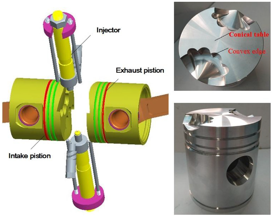
A LSCS for the OP2S diesel engine.
Materials and methods
Simulation model
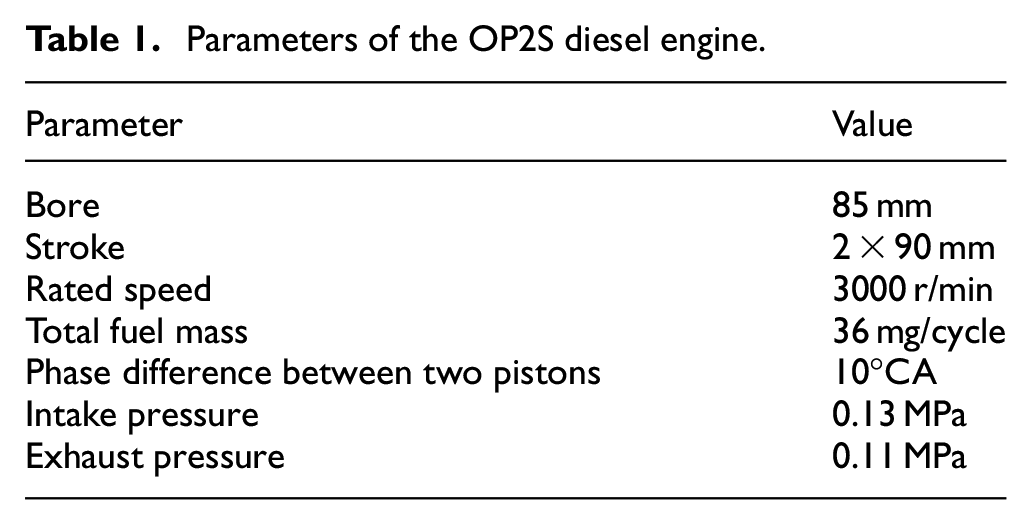
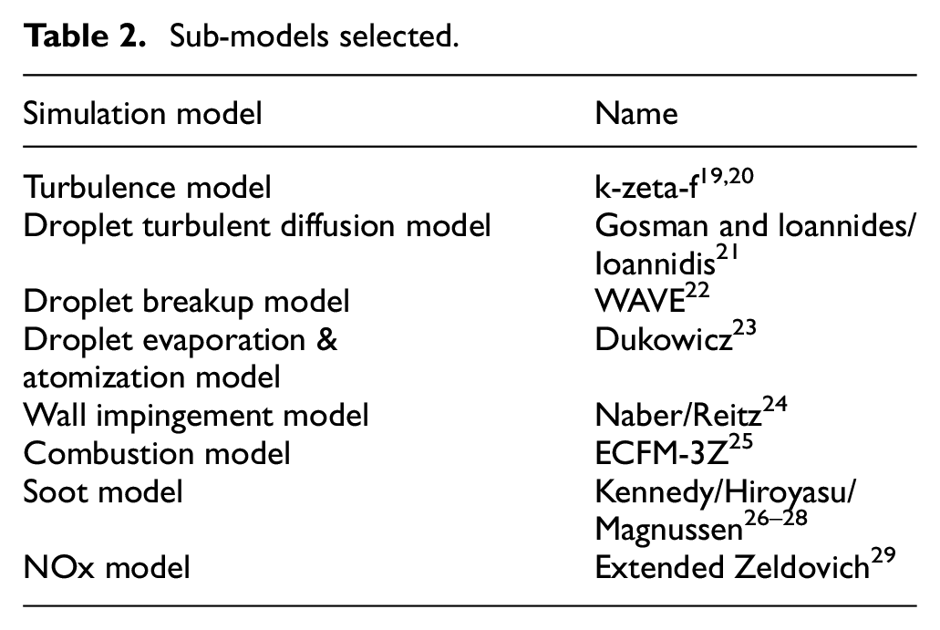
This work established a three-dimensional model of the combustion process of the OP2S diesel engine. The parameters of the OP2S diesel engine are shown in Table 1. In the combustion process of the OP2S diesel engine, only the interval from the closing of the intake port to the opening of the exhaust port was considered. The intake port height is 20 mm and the exhaust port height is 24 mm. According to the intake condition (0.13 MPa and 293 K) and the opening and closing time of ports, we calculated the initial condition (0.16 MPa and 390 K). Considering that the OP2S diesel engine adopts dual fuel injectors oppositely, and the combustion chamber is also symmetrical, a half model of the OP2S diesel engine was established in this work, as shown in Figure 3. The model uses computational boundary conditions, including intake piston temperature (523 K), exhaust piston temperature (623 K), cylinder temperature (573 K), and symmetry face. The model has two moving pistons. To coordinate the motion of the two pistons, a stationary surface was set in the middle of the cylinder, and the motion law of the two pistons was substituted to complete the moving mesh. To ensure the accuracy of the spray calculation, the grid direction was radially distributed along the spray direction as shown in Figure 4. The sub-models selected in the model are shown in Table 2.
Parameters of the OP2S diesel engine.
Sub-models selected.
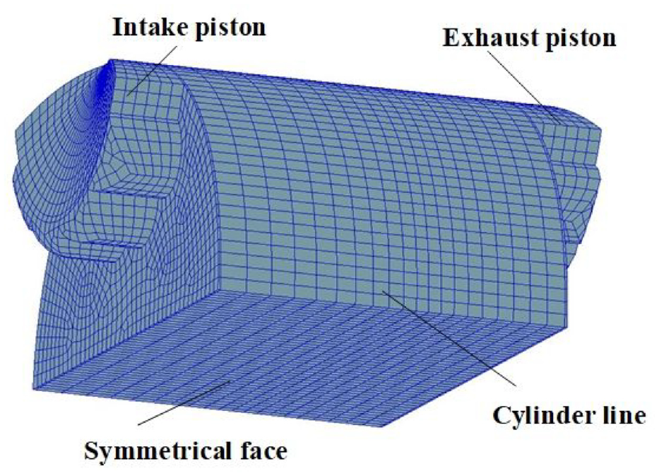
Three-dimensional model of the combustion process of the OP2S diesel engine.
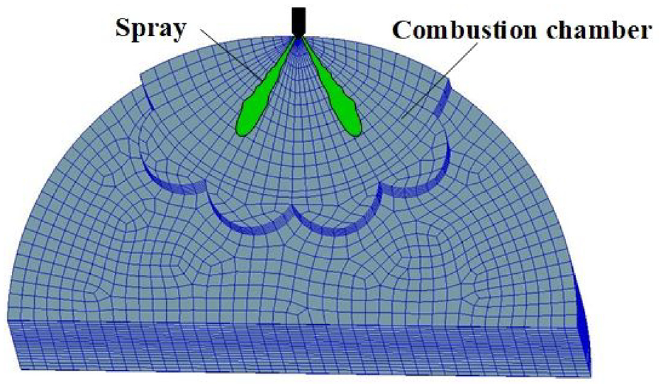
Radial mesh model for the combustion chamber.
Verification and validation
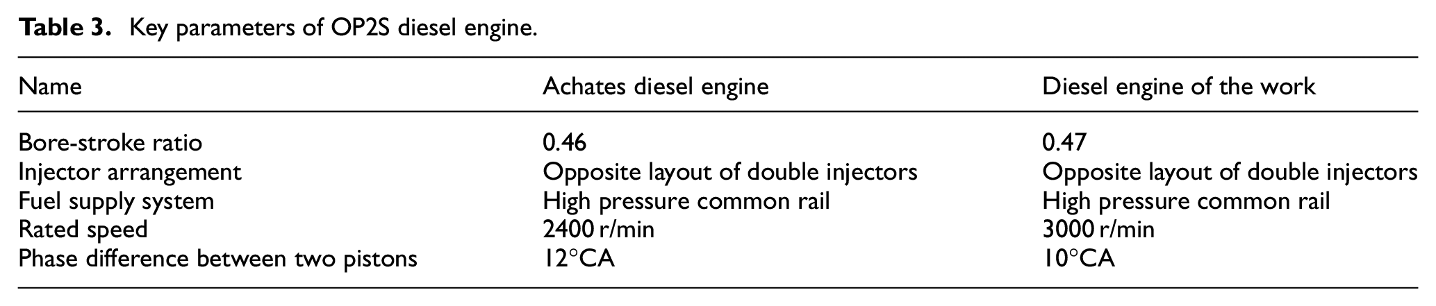
To ensure the accuracy of the simulation calculation, this work selected the Achates OP2S diesel engine, which is similar to the OP2S diesel engine in this study with key parameters such as cylinder bore-stroke ratio and injector arrangement as a reference. In this work, the Achates OP2S diesel engine model was first established, and based on the test data of the OP2S diesel engine, 9 the combustion model and spray model used in the three-dimensional simulation model are verified. The verification results are shown in Figure 5. Figure 5 shows that the cylinder pressure and heat release rate curves have a good agreement. The relative error of the cylinder pressure is less than 10%, which can ensure the accuracy of calculation results. The slope of the heat release rate for simulation and experiment is shown in Figure 6. They also have a good agreement. Furthermore, the MFB50 (Crank angle at which 50% of fuel mass fraction has burned) for simulation is 5.3°CA, while the MFB50 for the experiment is 4.8°CA. Their relative error is 10.4%. The MFB90 (Crank angle at which 50% of fuel mass fraction has burned) for the simulation is 22°CA, while the MFB90 for the experiment is 19.5°CA. Their relative error is 12.8%. Since the OP2S diesel engine studied in this work is close to the Achates OP2S diesel engine, as shown in Table 3. Therefore, the OP2S diesel engine model established in this work can use the previously verified model and select related model parameters. At the same time, to ensure the accuracy of the emission model, the emission model in this work was selected concerning the traditional four-stroke diesel engine.
Key parameters of OP2S diesel engine.
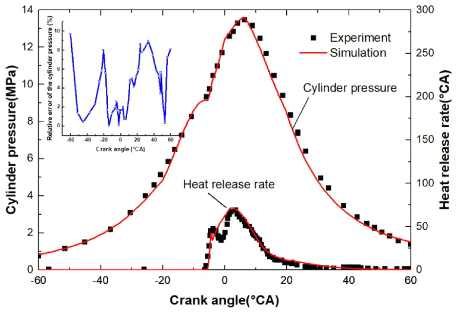
Comparison of simulation and experiment.
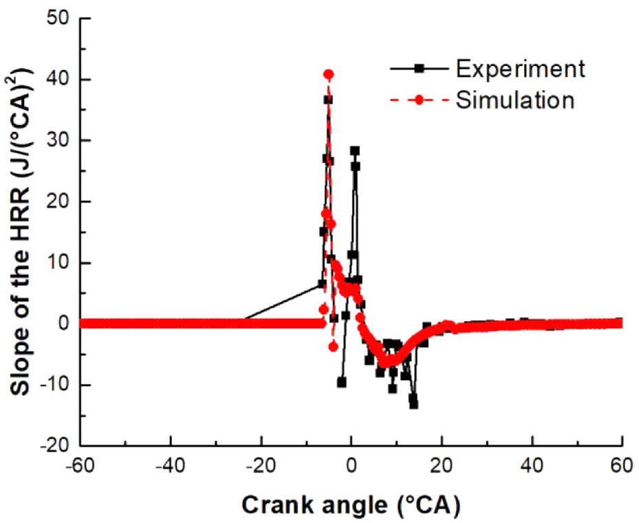
Slope of the heat release rate.
Influence of combustion chamber parameters
The parameters of the lateral swirl combustion chamber in the OP2S diesel engine mainly include convex edge parameters and conical table parameters, as shown in Figure 7. The convex edge parameters mainly include the radius of the combustion chamber R, the distribution angle of the convex edge β, and the height of the convex edge ha. The convex edge parameters mainly determine the split-flow effect of the lateral swirl combustion chamber. The split-flow effect refers to dividing a bundle of fuel into multiple bundles by the convex edge to promote fuel/air mixing. The conical table parameters mainly include the height of the conical table ht, the radius of the conical table rt, the inclination angle of the conical table δt, and the transition arc rc. The conical table parameters mainly determine the containment effect of the lateral swirl combustion chamber on the fuel spray. The lateral swirl combustion chamber belongs to the diversion-type combustion chamber. The parameters affecting its mixed combustion performance are mainly the convex edge parameters that have the split-flow. In addition, among the parameters of the containment effect, the inclination angle δt of the conical table is the main influencing parameter. 30 Therefore, in this study, the combustion chamber radius R, the distribution angle of the convex edge β, the convex edge height ha, and the inclination angle of the conical table δt are selected as the main parameters, and other parameters are used as tuning parameters to ensure that each calculation case has the same compression ratio.
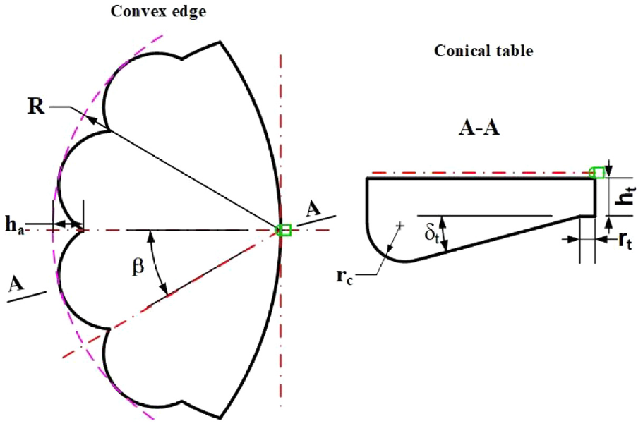
Parameters of the lateral swirl combustion chamber in the OP2S diesel engine.
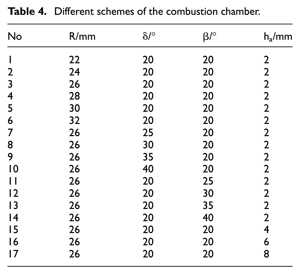
Based on the original model parameters, different combustion chamber schemes are designed and established, as shown in Table 4, of which scheme 3 is the basic combustion chamber. To explore the mechanism that different combustion chamber parameters affect the mixing and combustion performance of the LSCS in the OP2S diesel engine, this work analyzed the equivalence ratio of fuel distribution in three sections of the lateral swirl combustion chamber respectively. The positions of the three sections are shown in Figure 8, where the A section is the location of the incident convex edge, the B section is the location of the convex edge plane, and the C section is the position of the gap between two pistons.
Different schemes of the combustion chamber.
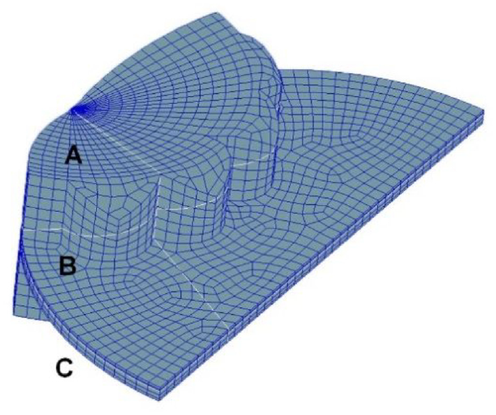
Three sections of the lateral swirl combustion chamber in the OP2S diesel engine.
Combustion chamber radius
Figure 9 shows the combustion chamber structure under different combustion chamber radiuses. The combustion chamber radius varies from 22 to 32 mm. Under the same volume of the combustion chamber, the increase of the combustion chamber radius shallows the combustion chamber depth gradually. Correspondingly, the conical table radius is adjusted from 0 to 1.6 mm, the conical table height is adjusted from 0 to 6.1 mm, and the transition arc radius is adjusted from 2.0 to 2.9 mm. When R changes, the combustion chamber depth changes significantly, resulting in a change in the optimal angle of the fuel jet. Therefore, three spray angles of 110°, 115°, and 120° were taken under each combustion chamber respectively. The comparison results of the indicated power are shown in Figure 10. Figure 10 shows that the indicated power of the combustion chamber reaches the optimum value at 115°. On this basis, the influence of different combustion chamber radiuses on the performance of the LSCS in the OP2S diesel engine is studied. Meanwhile, the sensitivity analysis of the injection time is shown in Figure 11. We obtain the optimal injection time by comparing the indicated powers under different injection times. This method also was used in other cases.
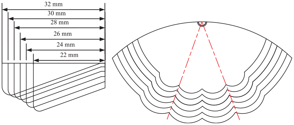
Combustion chamber structure under different combustion chamber radiuses.
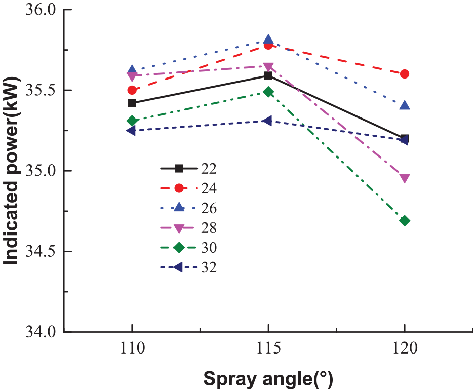
Matching results of the spray angle under different combustion chamber radiuses.
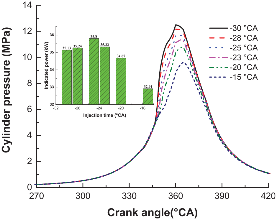
Sensitivity analysis of the injection time for the case with a radius of 26 mm.
Figure 12 shows the effect of different combustion chamber radiuses on indicated power, Soot, and NOx. When the combustion chamber radius R is 26 mm, the indicated power reaches the maximum value and the soot emission reaches the minimum value. When the R decreases or increases from 26 mm, the indicated power of the LSCS in the OP2S diesel engine decreases, the soot emission increases and the NOx emission decreases. After the R exceeds 28 mm, the indicated power reduces significantly.
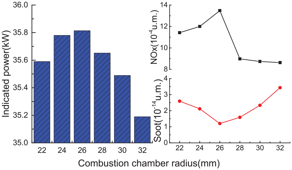
Indicated power, soot, and NOx under different combustion chamber radiuses.
Figure 13 shows the distribution of fuel equivalence ratio under different combustion chamber radiuses. In the A section, as the combustion chamber radius increases, the unused space on both sides of the spray gradually decreases. In the B section, with the continuous increase of the combustion chamber radius, the unused space on both sides of the spray gradually increases. Meanwhile, before the combustion chamber radius reaches 26 mm, the convex edge shows the significant split-flow effect; After the combustion chamber radius exceeds 26 mm, the greater distance will weaken the spray energy of impinging the convex edge. Combining with Figure 12, it can be shown that under the current fuel supply condition, it is necessary to make good use of the space of the axial section (section A) and the radial section (section B) at the same time, to enhance the split-flow of the convex edge for better performance.
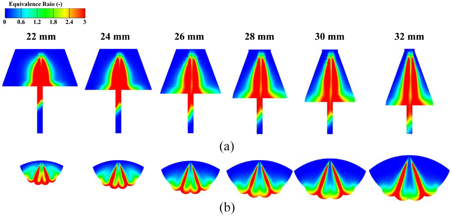
Distribution of fuel equivalence ratio under different combustion chamber radiuses: (a) A section and (b) B section.
Inclination angle of the conical table
Figure 14 shows the combustion chamber structure under different inclination angles of the conical table. The inclination angles of the conical table δt vary from 20° to 40°. Under the same volume of the combustion chamber, the increase of inclination angles of the conical table deepens the combustion chamber gradually. Correspondingly, the conical table radius is adjusted from 0 mm to 1.8 mm, the conical table height is adjusted from 0to 6.1 mm, and the transition arc radius is adjusted from 2.0 mm to 2.6 mm. After optimization, the Spray angle is 115° under different inclination angles.
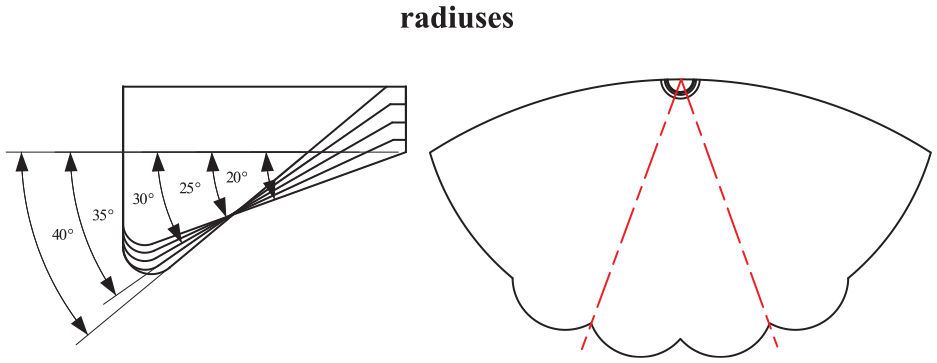
Combustion chamber structure under different inclination angles of the conical table.
Figure 15 shows the effects of different inclination angles of the conical table on indicated power, Soot, and NOx. When the inclination angle of the conical table reaches 20°, the indicated power is the largest and the NOx also keeps a high level. With the increase of the inclination angle of the conical table, the indicated power and NOx gradually decreased, while the soot showed a gradually increasing trend but the change range was small. This indicated that the inclination angle of the conical table had little effect on the uniformity of mixing.
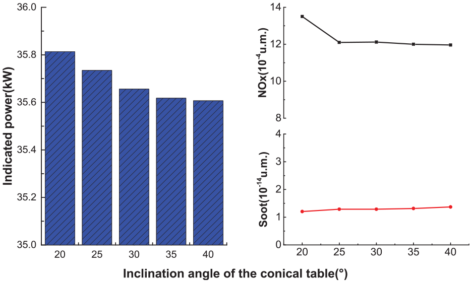
Indicated power, Soot, and NOx under different inclination angles of the conical table.
Figure 16 shows the distribution of fuel equivalence ratio under different inclination angles of the conical table. In the B section, the lateral swirl parameters remain unchanged. The increase of the inclination angle of the conical table does not have a significant influence on the distribution of fuel. This indicates that the inclination angle does not affect the split-flow effect of the convex edge. In the A section, with the continuous increase of the inclination angle, the fuel distribution changes little.
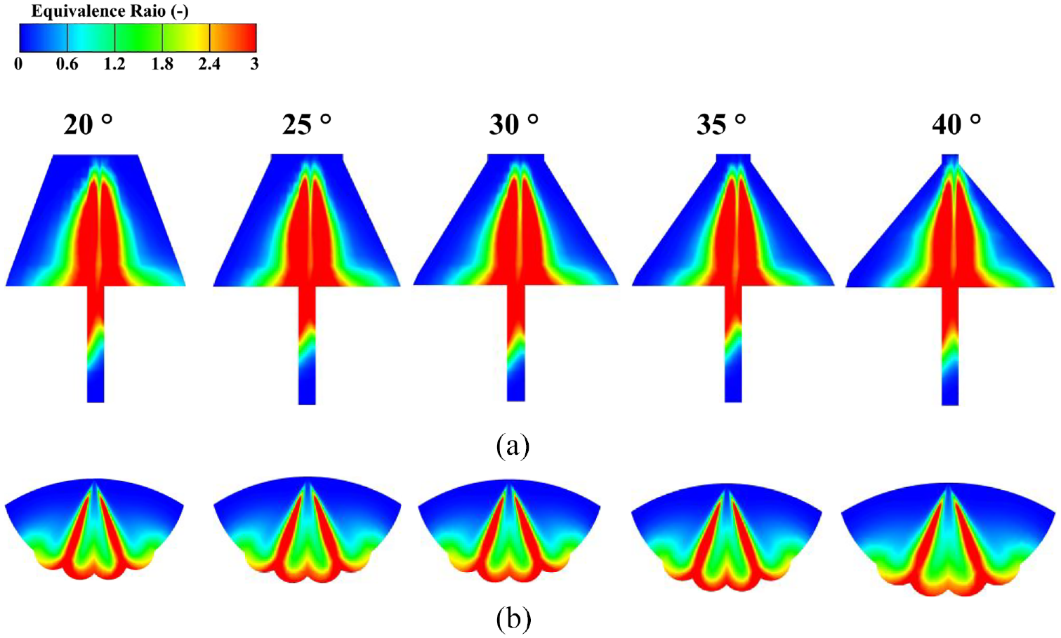
Distribution of fuel equivalence ratio under different inclination angles of the conical table: (a) A section and(b) B section.
Distribution angles of the convex edge
Figure 17 shows the combustion chamber structure under different distribution angles of the convex edge. The distribution angle of the convex edge varies from 20° to 40°. Under the same volume of the combustion chamber, the increase of the distribution angle of the convex edge shallow the combustion chamber depth gradually, and the shallowness is not large. Correspondingly, the conical table radius is adjusted from 0 to 1.8 mm, the conical table height is adjusted from 5.8 to 6.1 mm, and the transition arc radius is adjusted from 2.0 to 2.6 mm. After optimization, the spray angle is 115° under different distribution angles of the convex edge.
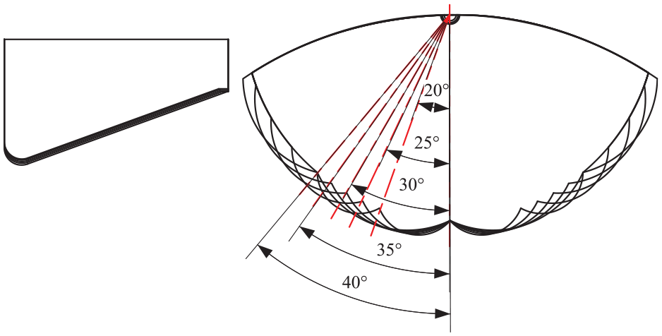
Combustion chamber structure under different distribution angles of the convex edge.
Figure 18 shows the effects of different distribution angles of the convex edge on indicated power, Soot, and NOx. When the distribution angle of the convex edge β reaches 25°, the indicated power is the largest and the soot emission is the lowest. When the distribution angle of the convex edge β decreases or increases from 25°, the indicated power of the OP2S diesel engine decreases, the soot emission increases, and the NOx emission decreases, deteriorating combustion characteristics.
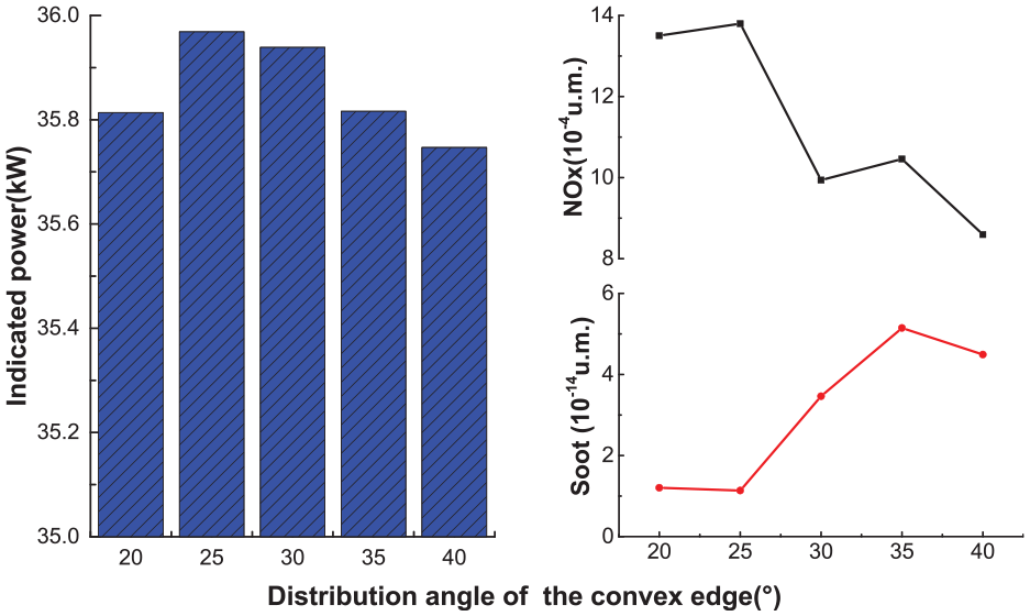
Indicated power, Soot, and NOx under different distribution angles of the convex edge.
Figure 19 shows the distribution of the fuel equivalence ratio under different distribution angles of the convex edge. In the A section, with the increasing distribution angle of the convex edge, the fuel injected into the gap between the two pistons gradually decreases. Part of the fuel distributed in the gap is conducive to making full use of the squish movement to speed up the mixing and combustion. Meanwhile, with the continuous increase of the distribution angle of the convex edge, part of the fuel near the convex edge in the combustion chamber will gradually accumulate, deteriorating combustion. In the B section, the continuous increase of the distribution angle of the convex edge weakens the mutual interference between the adjacent two bundles of the fuel spray, worsening combustion.
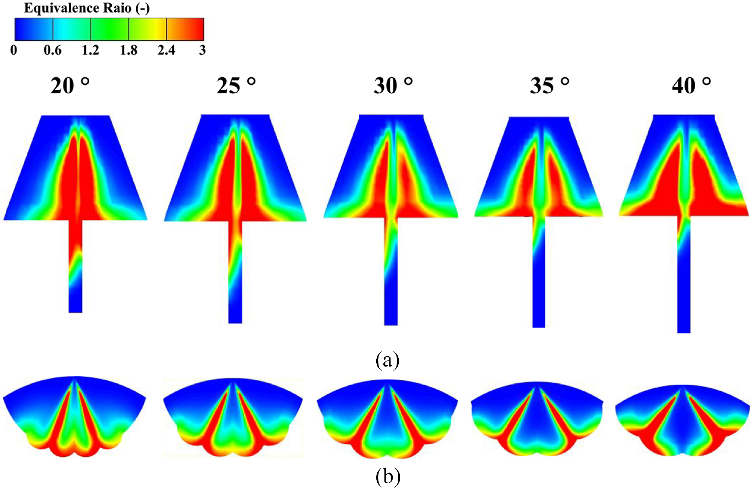
Distribution of fuel equivalence ratio under different distribution angles of the convex edge: (a) A section and(b) B section.
Convex edge height
Figure 20 shows the combustion chamber structure under different convex edge heights. The convex edge height varies from 2 to 8 mm. Under the same volume of the combustion chamber, the increase of the convex edge height shallows the combustion chamber depth gradually. Correspondingly, the conical table radius is 0 mm, the conical table height is adjusted from 6.1 to 11.1 mm, and the transition arc radius is adjusted from 1.8 to 2.0 mm.
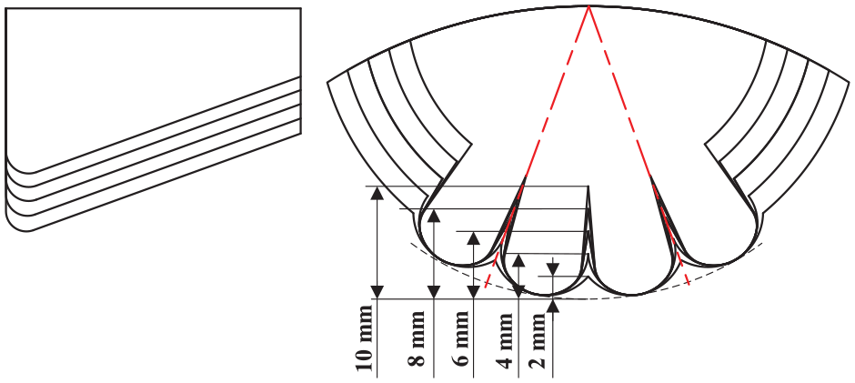
Combustion chamber structure under different convex edge heights.
Figure 21 shows the effect of different convex edge heights on indicated power, soot, and NOx. When the convex edge height reaches 4 mm, the indicated power is the largest, and the soot emission is the lowest. When the convex edge height ha is reduced or increased from 4 mm, the indicated power of the LSCS of the OP2S diesel engine decreases, the soot emission increases, and the NOx emission decreases, deteriorating the performance of the LSCS of the OP2S diesel engine decrease. After the convex edge height exceeds 4 mm, the indicated power reduces dramatically.
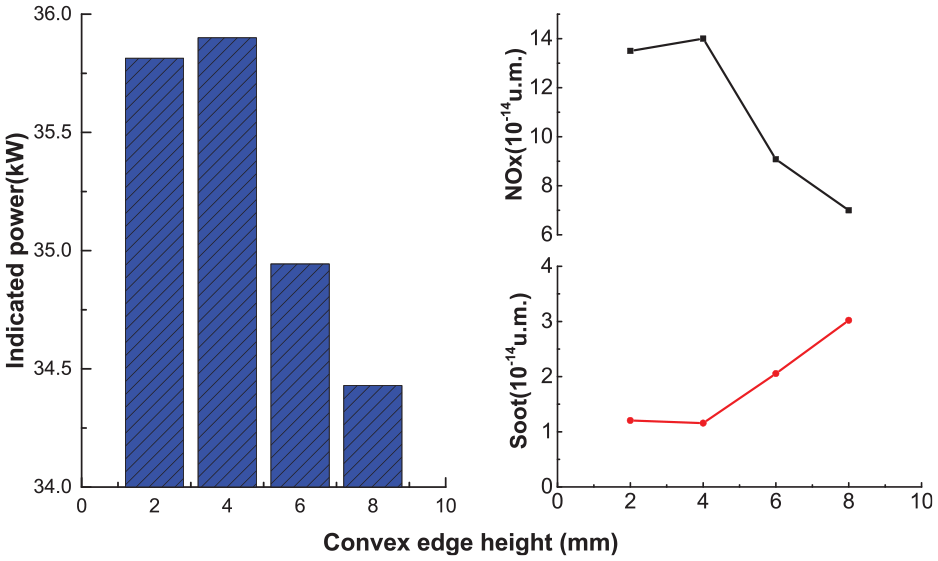
Indicated power, soot, and NOx under different convex edge heights.
Figure 22 shows the distribution of fuel equivalence ratios under different convex edge heights. In the A section, the increase of the convex edge height gradually increases the unused space on both sides of the spray, deteriorating the fuel-air mixing. Figure 22(b) shows that in the B section when the crankshaft angle reaches 350°CA, the increase of the convex edge height enhances the split-flow effect of the convex edge. Meanwhile, the interference wall jet moves faster. In addition, the increase of the convex edge height gradually forms a neck in the combustion chamber. The moving direction of the wall jet in the exit area progressively approaches the middle of the combustion chamber. Finally, the exported fuel gradually accumulates in the middle of the combustion chamber. When the crankshaft angle reaches 355°CA, with the increase of the convex edge height, the unused space near the wall of the combustion chamber gradually increases. The fuel with an equivalence ratio of 2.4 in the lateral swirl arc of the exit area gradually increases. So the higher convex edge height (6 mm and 8 mm) is not conducive to promoting the uniform mixing of fuel and air. Compared with 6 and 8 mm, the convex edge height of 2 mm will weaken the neck effect and the interference wall jet. The space in the combustion chamber cannot be fully utilized, deteriorating combustion.
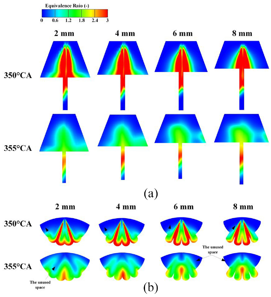
Distribution of fuel equivalence ratio under different convex edge heights: (a) A section and (b) B section.
Optimization of combustion chamber parameters
To optimize the combustion chamber structure of the OP2S diesel engine to improve the combustion system performance, this work firstly conducts a sensitivity analysis on the indicated power to clarify the influence degree of convex edge and conical table parameters on the combustion performance. The concept of sensitivity
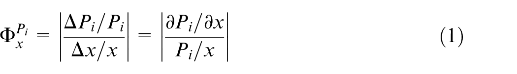
Figure 23 shows the average value and variation range of the sensitivity of combustion chamber parameters. The bar represents the average value of the sensitivity of each structural parameter, and the upper and lower deviation lines represent the variation range of the sensitivity under each calculation condition. The order of the sensitivity is: combustion chamber radius, convex edge height, distribution angle of the convex edge, and inclination angle of the conical table. Among them, the sensitivity and variation range of the convex edge parameters (R and ha) are large; the sensitivity and variation range of the convex edge parameter β and the conical table parameter δt is small. It can be seen that the combustion chamber radius and the convex edge height are the main influencing factors. When optimizing the combustion chamber, R and ha should be optimized first, and then the right β and δt should be matched.
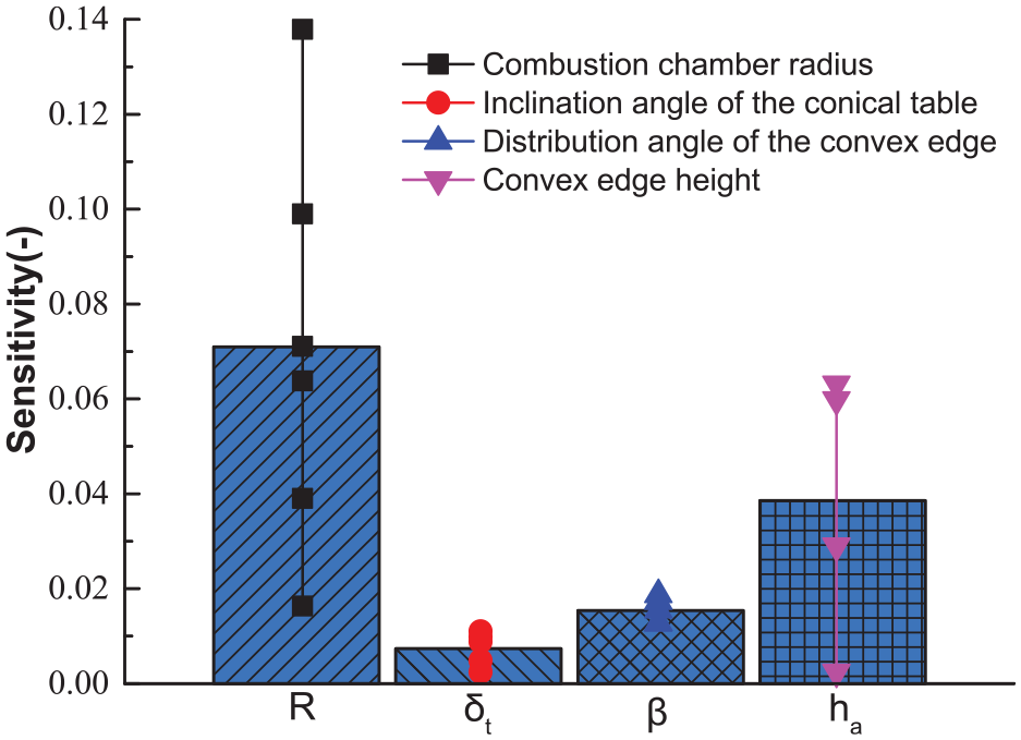
Average value and variation range of the sensitivity of combustion chamber parameters.
According to the influence order of the combustion chamber parameters on the combustion characteristics in the OP2S diesel engine, the combustion chamber parameters are optimized in turn. From the first round of optimization, the research order of the combustion chamber radius and the convex edge height are in line with the optimization order. So it can be obtained that the combustion chamber radius is 26 mm, and the convex edge height is 4 mm. Through the second round of optimization, the distribution angle of the convex edge and the inclination angle of the conical table are optimized, as shown in Figure 24. When the distribution angle of the convex edge reaches 25°, and the inclination angle of the conical table reaches 15°, the indicated power is the highest. The optimal combustion chamber is finally determined, as shown in Figure 25.
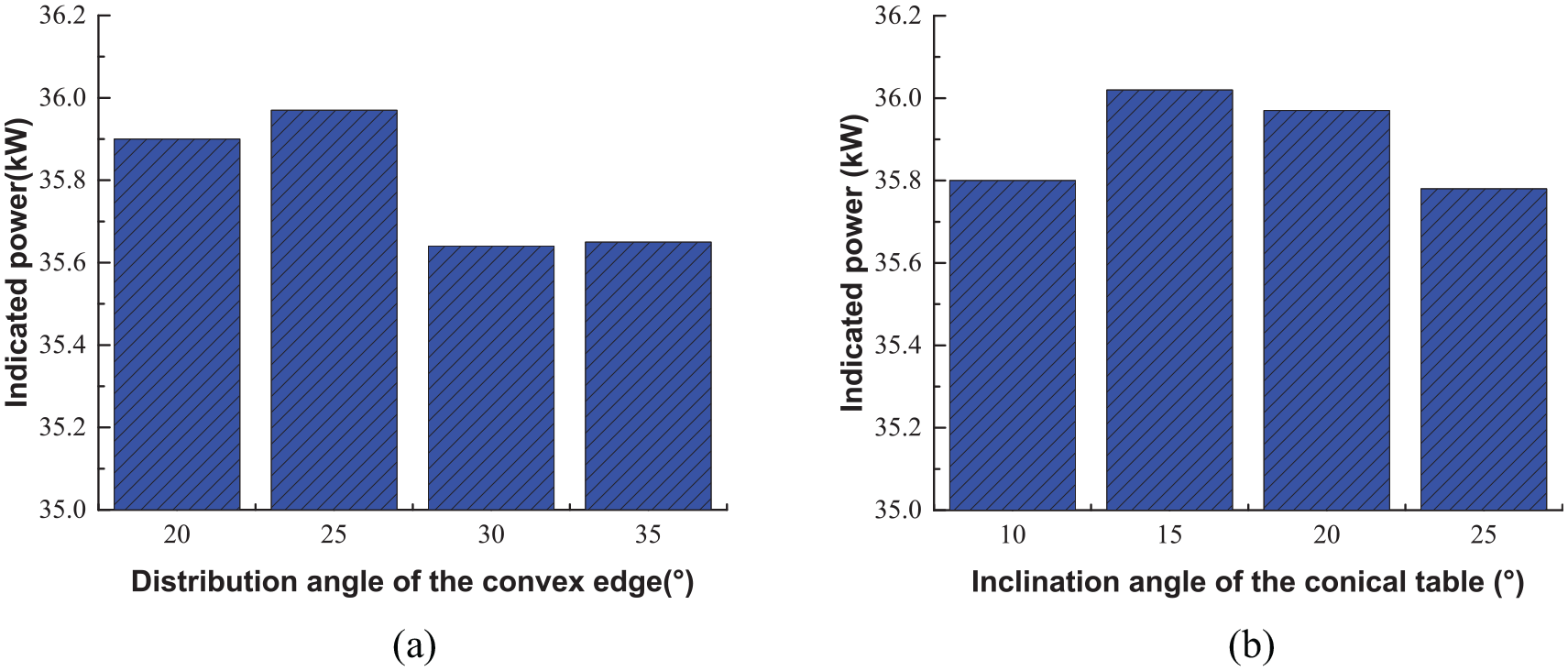
Optimization of the distribution angle of the convex edge and the inclination angle of the conical table: (a) Indicated power under different distribution angles of the convex edge and (b) Indicated power under different inclination angles of the conical table.
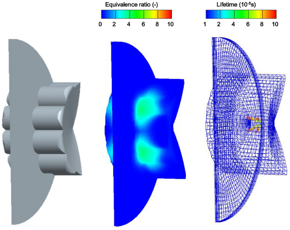
Optimal combustion chamber and sprays of the OP2S diesel engine.
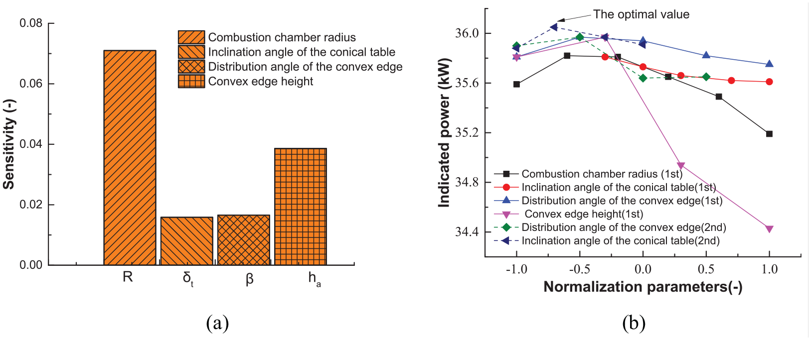
To further confirm the accuracy of the optimization results, the sensitivity and indicated power were inspected, as shown in Figure 26. Figure 26(a) shows that the sensitivity order of the combustion parameters is still the same as the sensitivity order obtained in the first round of calculation. This indicates that the sensitivity order of the combustion chamber parameters is reasonable. The structural parameters in all simulation cases are normalized, (
1) Determining the variation range of each parameter

Sensitivity analysis and normalization optimization: (a) Sensitivity analysis and (b) Normalization optimization.
where
2) Normalizing the levels of the parameter

Where
By normalizing all combustion chamber parameters of the OP2S diesel engine, this work obtains the normalized indicated power for all cases, as shown in Figure 26(b). According to the first round of optimization, the combustion chamber radius, the convex edge height, the distribution angle of the convex edge all have extreme points, but the extreme point has not appeared for the inclination angle of the conical table. This is since the value range cannot be further expanded under the restriction of other parameters. After the second round of optimization, the inclination angle of the conical table inclination parameter range was further widened, and the optimal solution was found at the same time. Through the two rounds of optimization, the optimal value obtained is the best under the current conditions, so it can be seen that the optimization process is effective. At the same time, it is also shown that the performance graphs of all cases after the normalization of the combustion chamber parameters can not only reflect the changes of all parameter values but also reflect the whole process of optimizing the combustion chamber parameters.
Conclusion
Based on the mixing and combustion mechanism of the traditional LSCS, this work proposed a LSCS suitable for OP2S diesel engines. This combustion system helps to improve the non-uniformity of mixing and combustion in the OP2S diesel engine, accelerate the combustion speed, and promote the power performance of the OP2S diesel engine and reduce soot emissions.
The parameters of the OP2S diesel engine lateral swirl combustion chamber mainly include convex edge parameters and conical table parameters. The convex edge parameters primarily determine the split-flow of the combustion chamber. The conical table parameters primarily determine the containment effect of the combustion chamber. The key parameters affecting the performance are the combustion chamber radius R, the distribution angle of the convex edge β, the convex edge height ha, and the inclination angle of the conical table δt.
This work studied the influence of key parameters such as the combustion chamber radius R, the inclination angle of the conical table δt, the distribution angle of the convex edge β, and the convex edge height ha on power and emission performances of the LSCS in the OP2S diesel engine. The results show that under certain fuel supply conditions, it is necessary to make good use of the space of the combustion axial section and the radial section at the same time, and enhance the split-flow effect of the convex edge, to promote the combustion efficiency of the LSCS in the OP2S diesel engine.
Using the sensitivity analysis method, it is determined that the sensitivity sequence is the combustion chamber radius, the convex edge height, the distribution angle of the convex edge, and the angle of the conical table. Furthermore, the parameter normalization method is used to obtain the structural parameters of the lateral swirl combustion chamber in the OP2S diesel engine. The results show the performance graphs of all cases after the normalization of the combustion chamber parameters can not only reflect the changes of all parameter values but also the whole process of optimizing the combustion chamber parameters.
Footnotes
Declaration of conflicting interests
The author(s) declared no potential conflicts of interest with respect to the research, authorship, and/or publication of this article.
Funding
The authors disclosed receipt of the following financial support for the research, authorship, and/or publication of this article: This research was supported by the Fundamental Research Program of Shanxi Province. (grant No. 20210302123072).